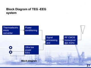
VIP ℂall Girls Vijay Nagar Hire Me Neha 96XXXXXXX Top Class ℂall Girl Serviℂe...
lalkrishn tripathi Malvian Seminar Report
1. Advance solar Energy System with
Thermoelectric Generator
1
Presented by:
LALKRISHN TRIPATHI
ROLL NO.- 2017032012
THERMOELECTRIC GENERATOR
Madan Mohan Malaviya University of Technology, Gorakhpur (U.P.)-
INDIA
Date: 06/02/2019
Guided by-
L.B.PRASAD SIR
AND BRIJESH
KUMAR SIR
3. INTRODUCTION
Energy crisis-main problem.
Increased pollution & population.
Tremendous energy wasted in the form of heat.
Constant uninterruptable power requirement.
Distorts the output performance.
Efficiency decreasing in electronic systems.
Increased interest in renewable energy.
Energy scavengers are modern trend.
SOLUTION???
THERMOELECTRIC GENERATORS 3
THERMO ELECTRIC GENERATOR
5. WHAT IS TEG??
Devices that convert temperature differences into
electrical energy.
Basic principle – “SEEBECK EFFECT” (power
generation).
PELTIER EFFECT
( Heating
and cooling purposes)
5
TEG Module
THERMO ELECTRIC GENERATOR
6. Working principle of TEG
Seebeck effect
6
Working Principle
THERMO ELECTRIC GENERATOR
N-Bi2Te3
P-Sb2Te3
7. THERMO ELECTRIC POWER GENERATION
7
It is based on SEEBECK EFFECT.
Heat is applied to a circuit at junction of different conductors a
current will be generated.
THOMAS JOHANN SEEBECK invented Seebeck effect in 1822.
The Magnitude of voltage generated is proportional to temperature
difference and depended on type of the conducting material
Seebeck coefficient defined as the open circuit voltage produced
between two points on a conductor when a uniform temperature
difference of 1k is applied between those points.
9. The simplest thermo electric generator consist of thermocouple of
n type and p type elements connected electrically in series and
thermally in parallel.
9
heat is input from one side and rejected from other
side.
a voltage will be generated across
Thermocouple.
The magnitude of the voltage is proportional to
the temperature gradient.
11. THERMO ELECTRIC HEATING AND
COOLING
11
These are based on PELTIER EFFECT
That is current is passes through a two dissimilar conductors there
will be a rise or fall of temperature at junction depending on
direction of current flow
Peltier effect discovered by Jean Peltier in 1834
Electrons moved from p type to n type, material absorbing thermal
energy from cold junctions.
Electrons dump their extra energy at hot junction as they flow from n
type to p type material through electric connector.
14. FABRICATION OF TEG
Highest performance can be obtained in presence of heavily doped
semiconductor such as Bismuth and silicon germanium.
TEG must be
a) Small in size
b) Light in weight
c) High silicon compatibility.
14
15. Fabrication process of thermo electric microconverters
1. The p type Sb2te3film is deposited by thermal co-evaporation
followed by Nickel
2. Photo resist and P type elements are patterned by photolithography.
3. Nickel is etched in chromium etchant, a Thermoelectric film is
patterned by wet etching HNO3.HCL and photo resist is removed.
4. The n type film deposited by co evaporation followed by 100m
nickel layer.
5. Photo resist is applied and patterned by photolithography for n type
element.
6. N type is etched in HNO3 and photo resist is removed, contacts are
deposited starting with a layer of nickel followed by 1µm of
aluminum and photo resist is removed.
7. A protective layer of Si3N4can also be deposited by low-temperature
hot wire chemical vapor deposition and patterned depending on
application. 15
17. FIGURE OF MERIT
THERMO ELECTRIC GENERATOR
The performance of thermoelectric devices depends on the figure of
merit (ZT) of the material , which is given by
Where,
α- Seebeck coefficient,
ρ - the electrical resistivity,
λ - the thermal conductivity, and
T – the temperature
A good thermal material must have
1. High Seebeck coefficient,
2. Low electric resistivity,
3. Low thermal conductivity.
17
18. CALCULATION
• For a single thermo couple
18
Open circuit voltage V = ( @ * dT) ……….. (1)
•
•
@ – Seebeck coefficient=
dT – diff in temp =
dV/dT
Th-Tc
(volt/Kelvin )
(Kelvin)
Current through the load, ……….. (2)
I= @ * DT
Rc+RL
•
•
RL– load resistance
Rc – internal resistance
19. Efficiency of the generator (Eg) is:
..............(3)
Eg = V x I
Qh
• The total heat input to the couple = Qh
T c = Temperature at cold junction
T h = Temperature at hot junction
19
22. •
22
Human body temperature 270
c to 360
c
• Forehead & Nose have little high temperature
Epilepsy or Sleep monitoring
Patient while doing exercise
Regular medical data automatically recorded
•
•
•
•
•
Comfort for the subject ( human or animal )
No need to replace or recharge the battery
23. •
•
•
•
•
Air conditioner business developed recently
CFC emission increased
Alternative should be found out
Peltier effect is being used
Beneficial to use because
1. Low maintenance
2. Long life
3. No moving parts
4. Can be used for microchip
cooling
23
TEG for Cooling
24. Low power devices such as wrist watches and hearing
aids
24
Thermic watch
THERMO ELECTRIC GENERATOR
25. Easy to use
Maintenance free
Long life
Good for daily use
Uninterruptable power so no risk
Watches were first brought by
SEIKO & CITIZEN
25
thermic watch by SEIKO
30. Advantages
30
Solid state construction, no moving part, no vibration.
Available 24 hours a day.
No noise and low maintenance.
Convenient power supply.
Stabilize temperature of devices.
Increase operation life under all environment.
Space and military applications.
Performance output highly scalable.
Waste Heat – Electricity.
Space requirement is only 1/20th of a solar cell.
Portable power.
Less weight than a battery.
THERMO ELECTRIC GENERATOR
32. Conclusion
32
THERMO ELECTRIC GENERATOR
TEG to supply low power electronics ( milli watts).
Waste heat conversion to useful energy beneficial to
present energy crisis.
Numerous advantages over disadvantages.
Variety of application field.
Introduction of nanotechnology.
Development in future will lead to interesting
applications.