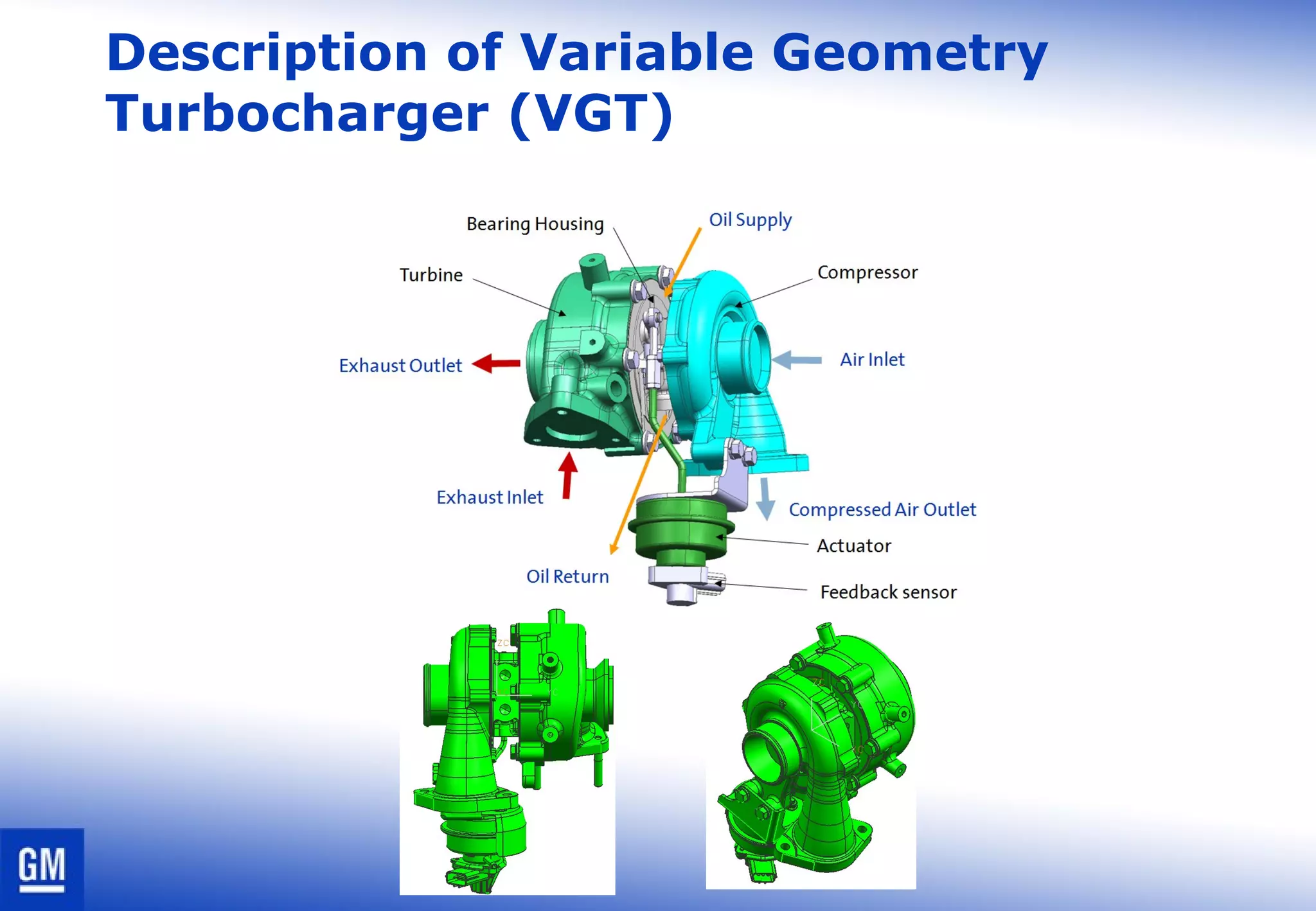
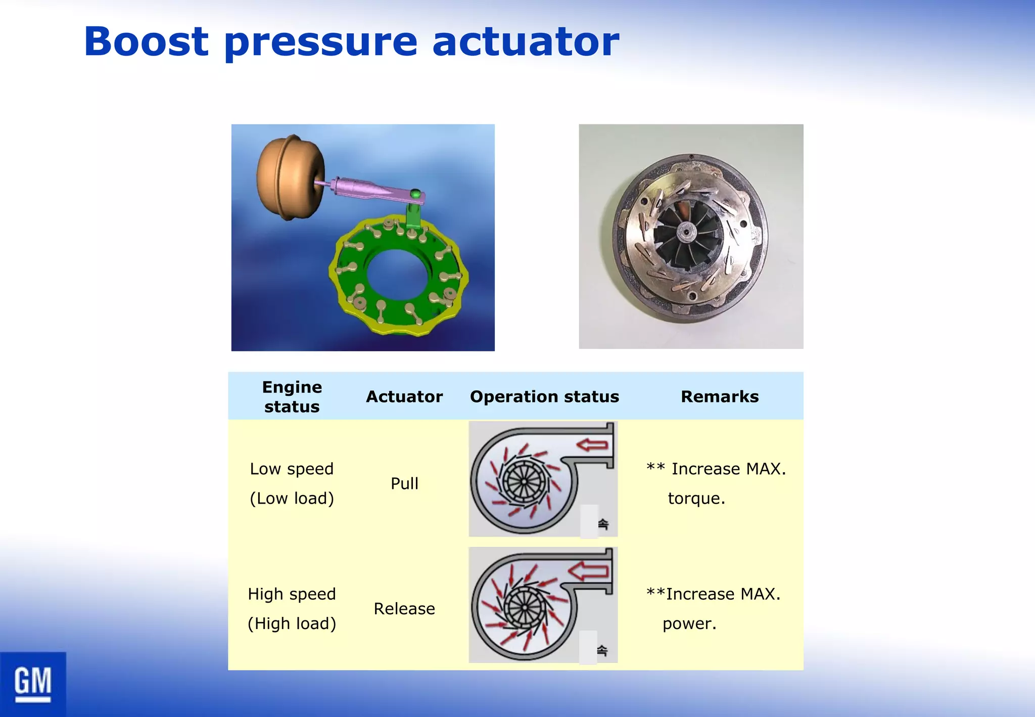
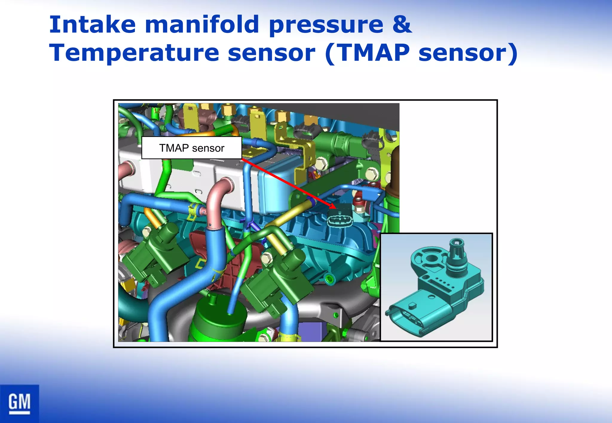
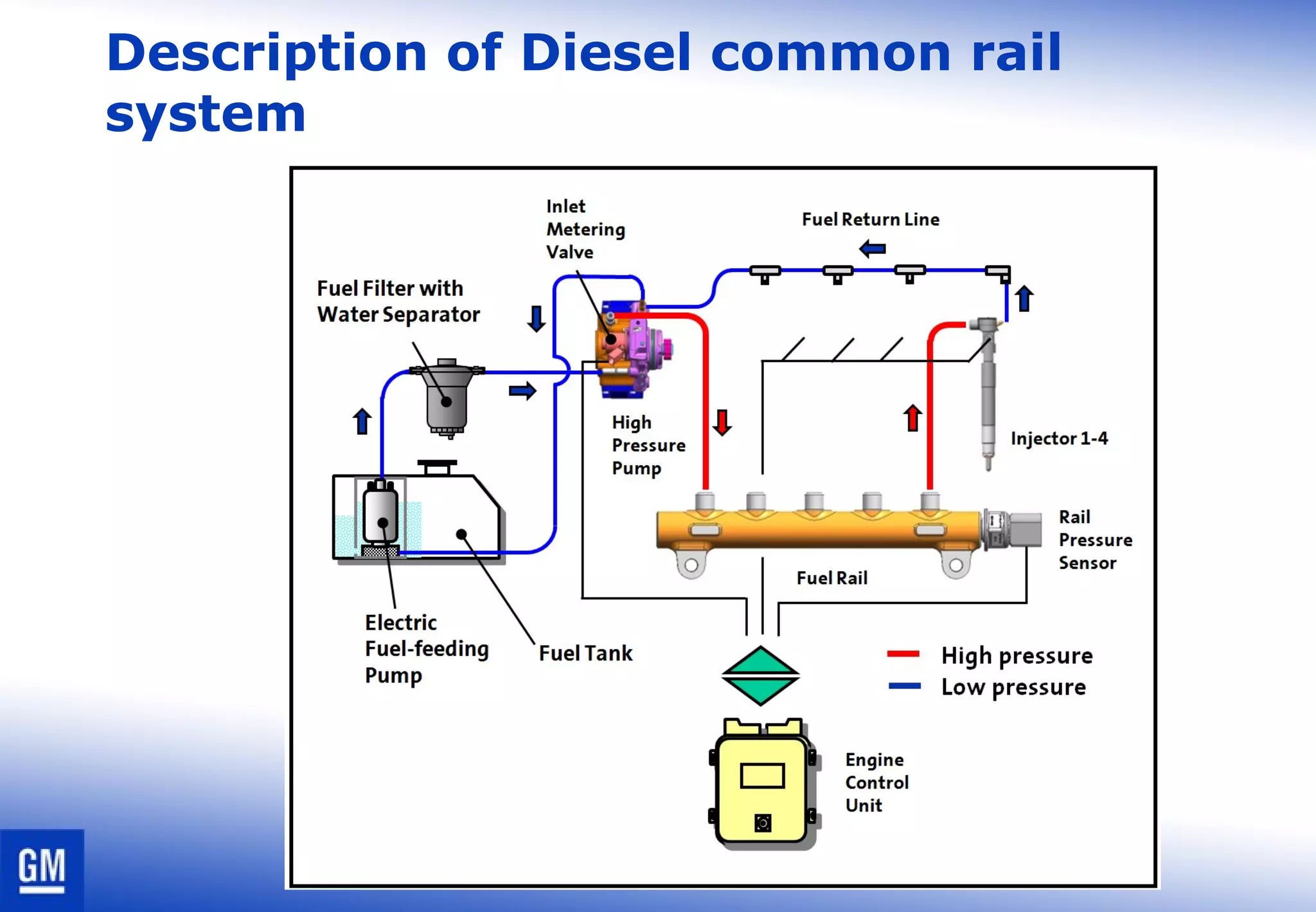
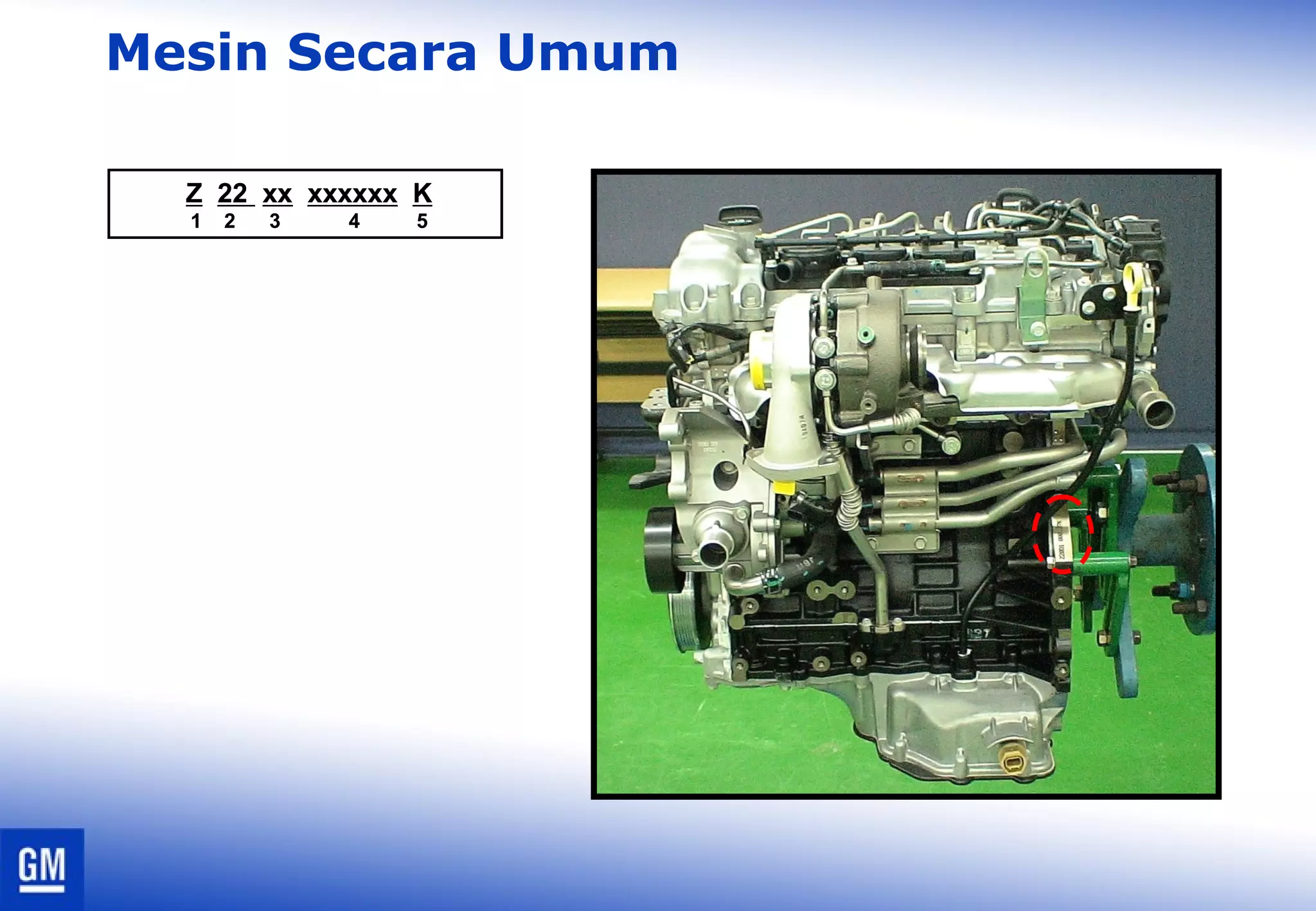
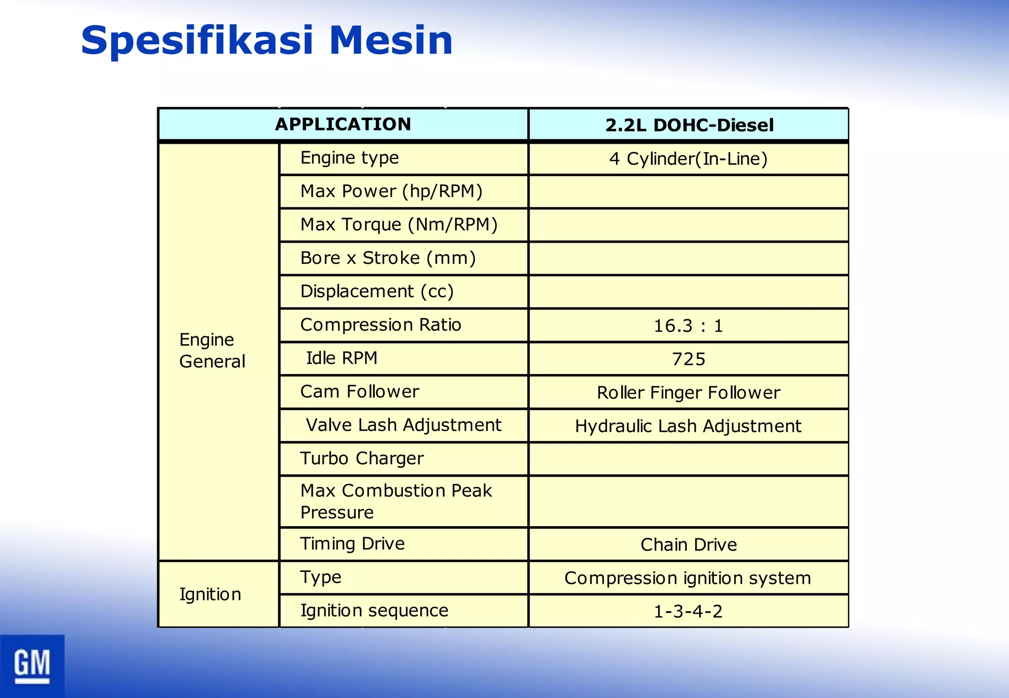
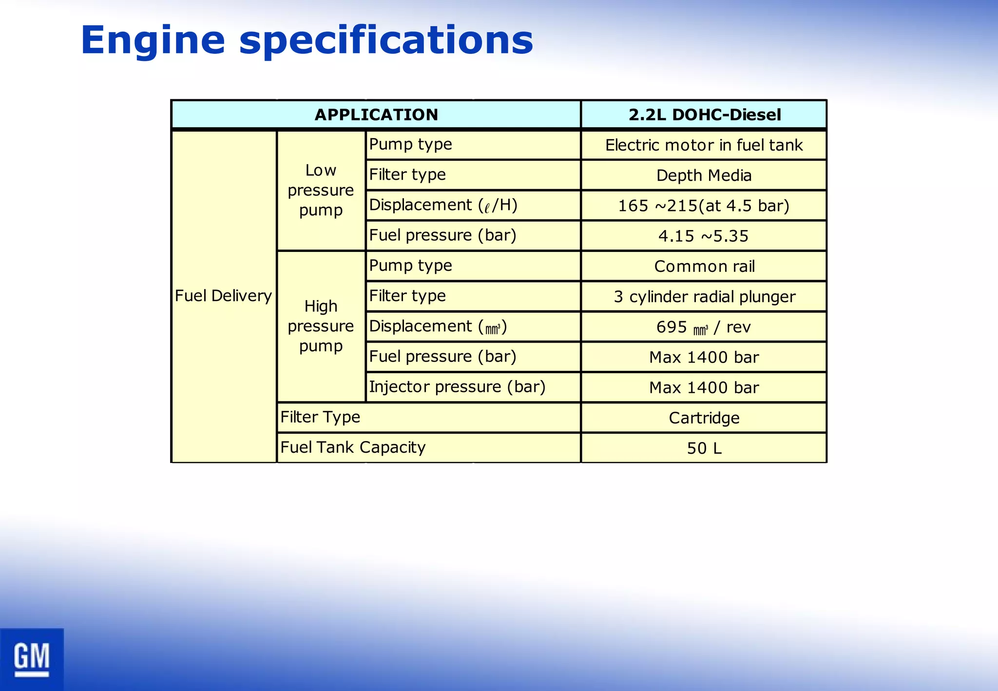
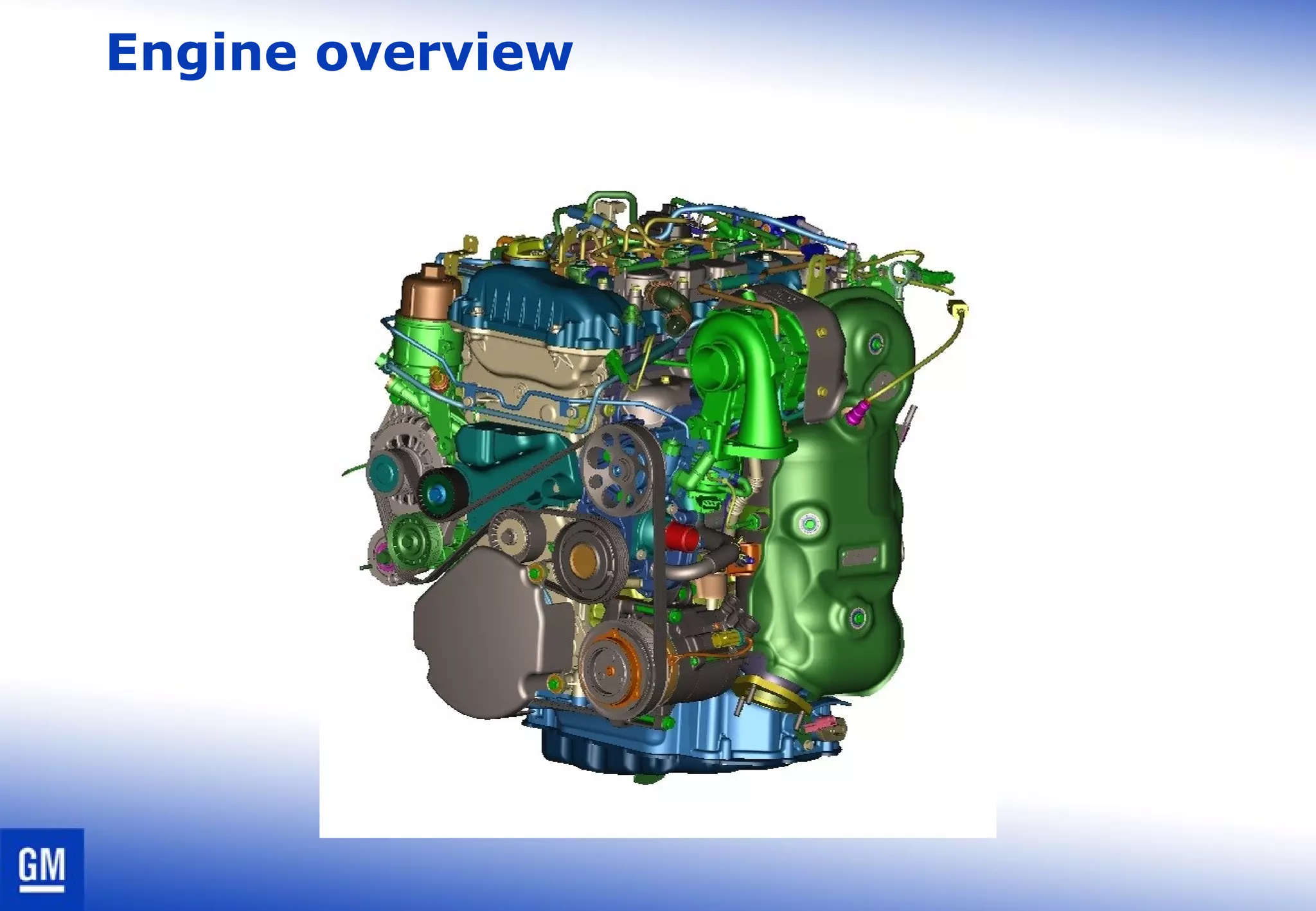
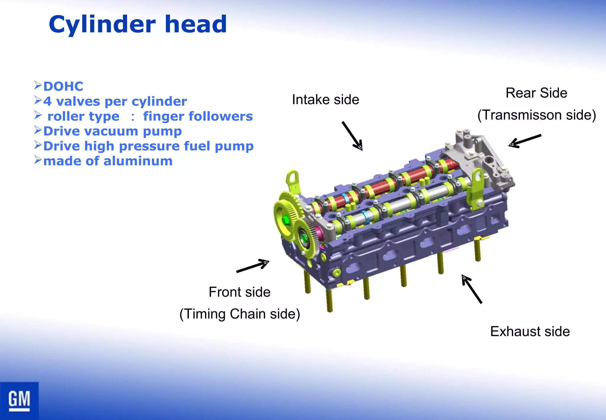
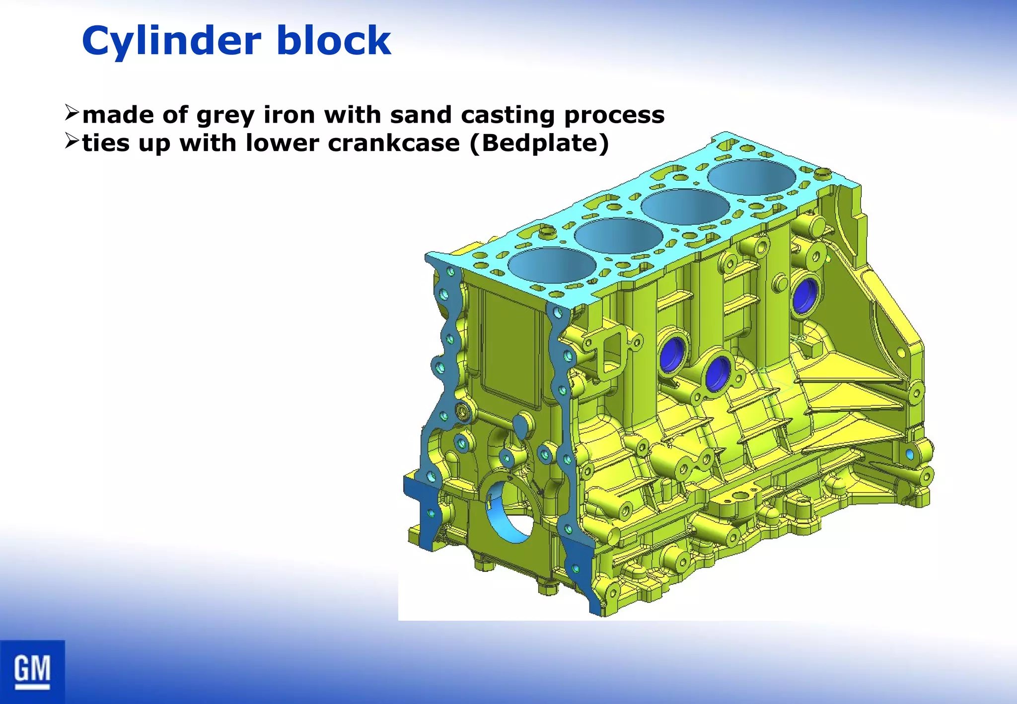
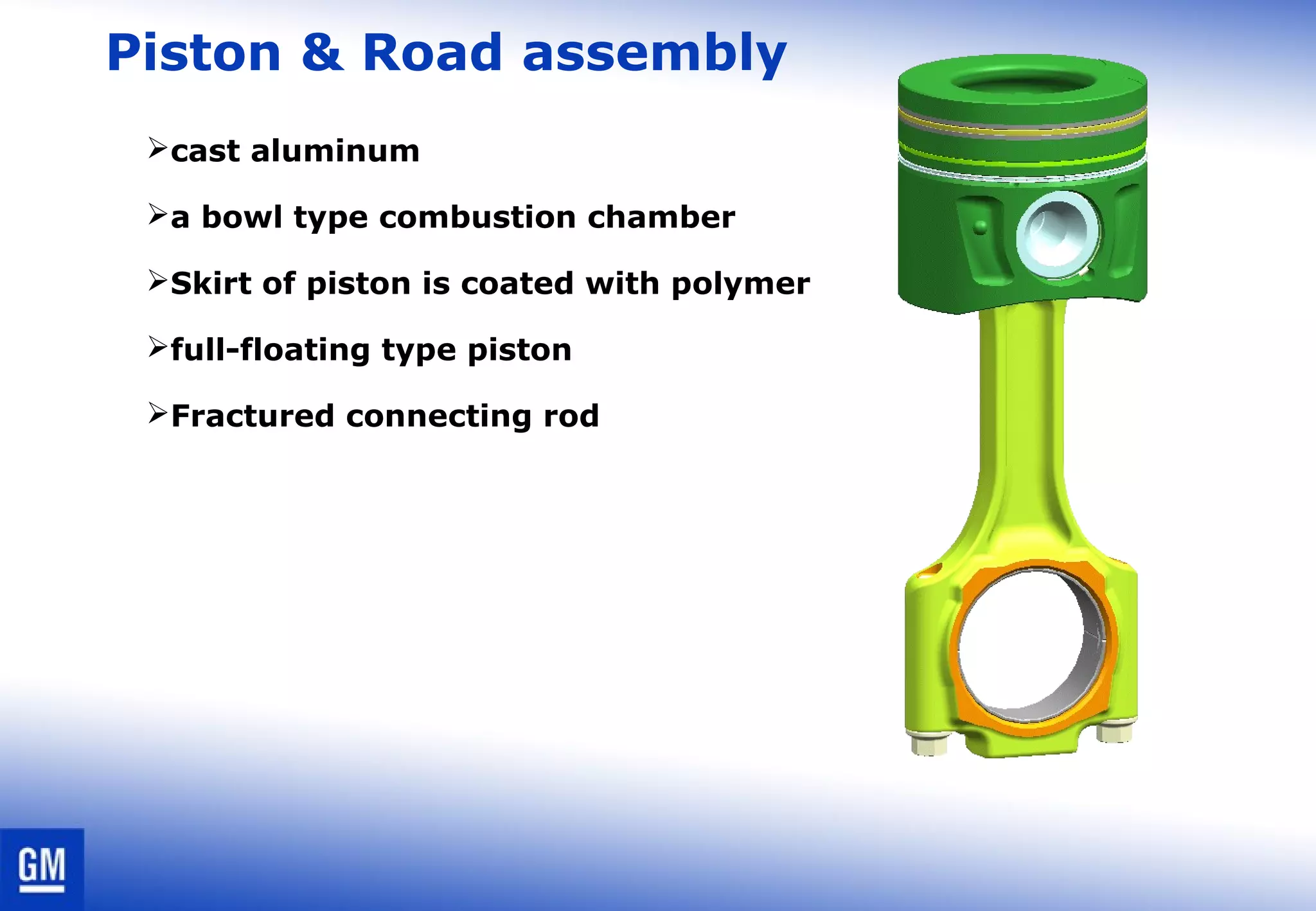
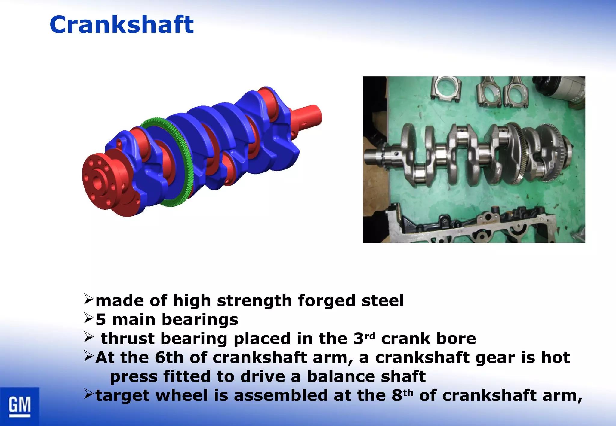
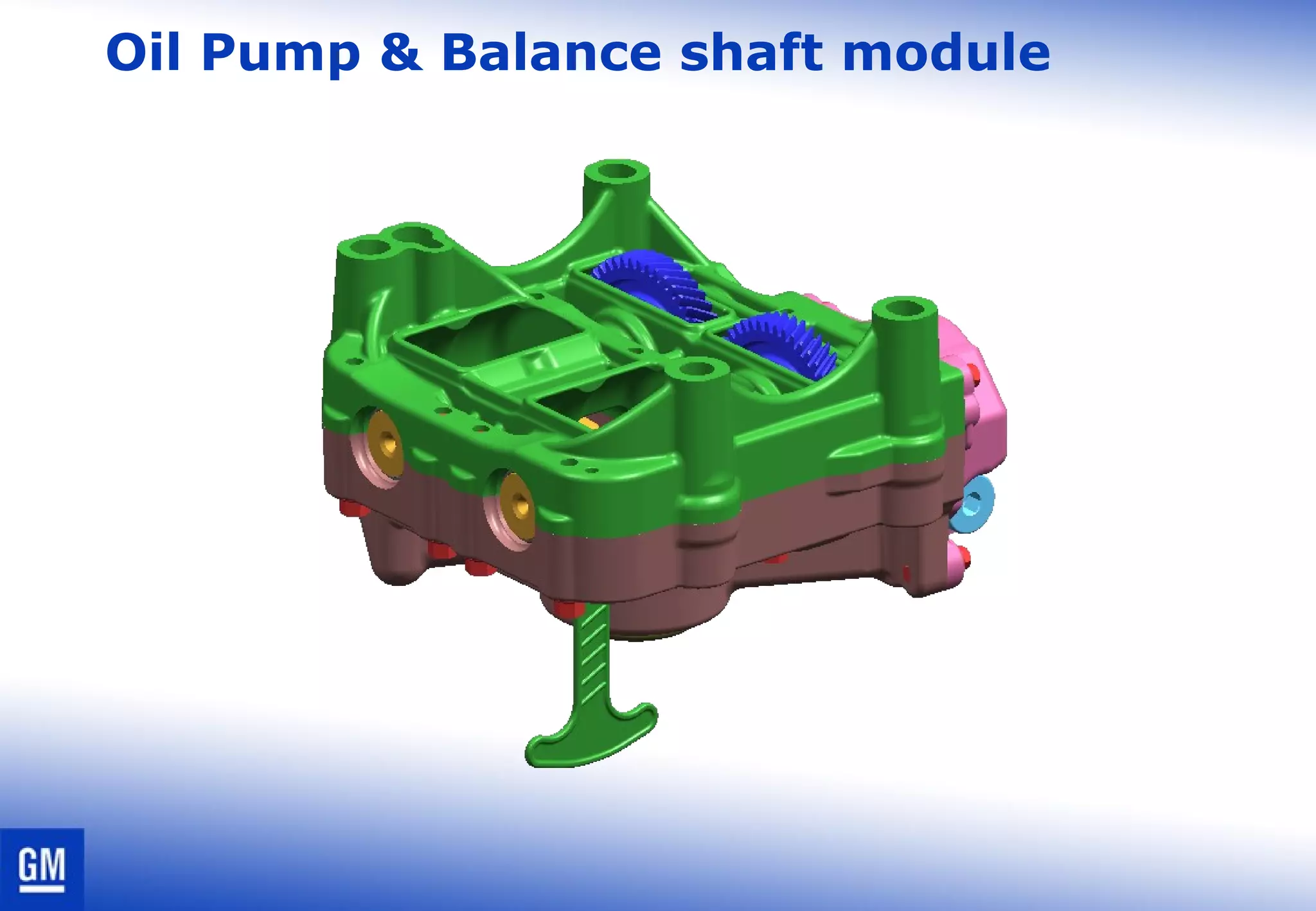
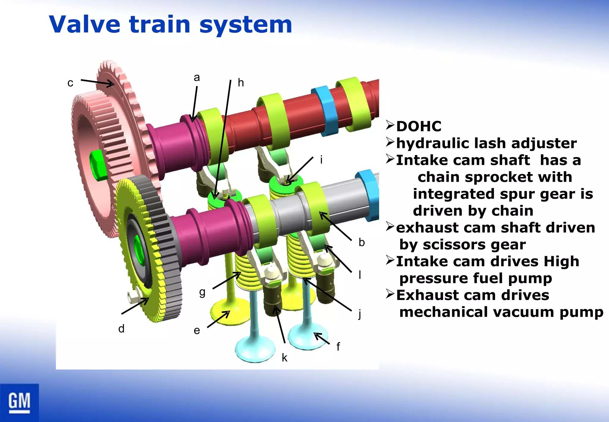
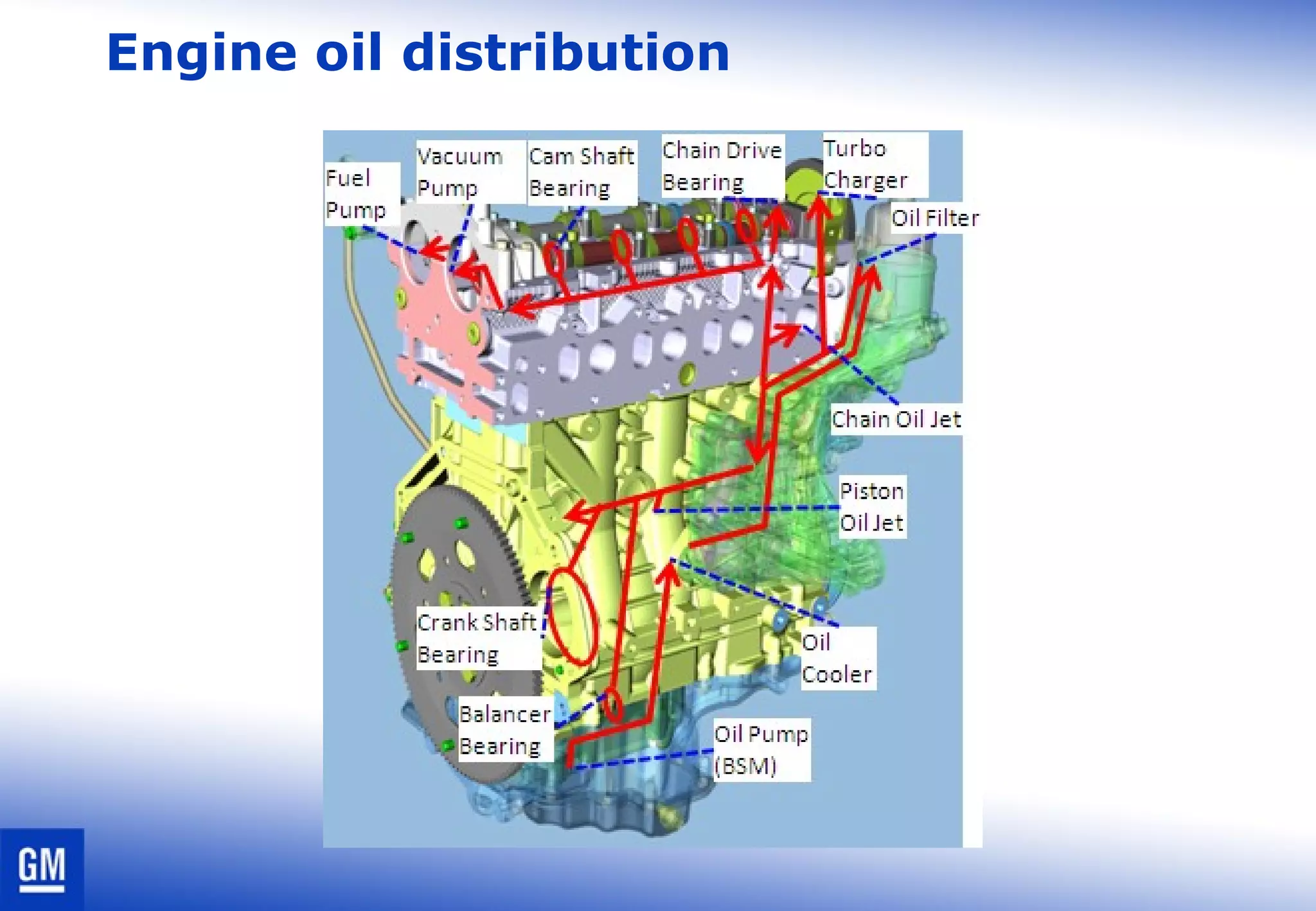
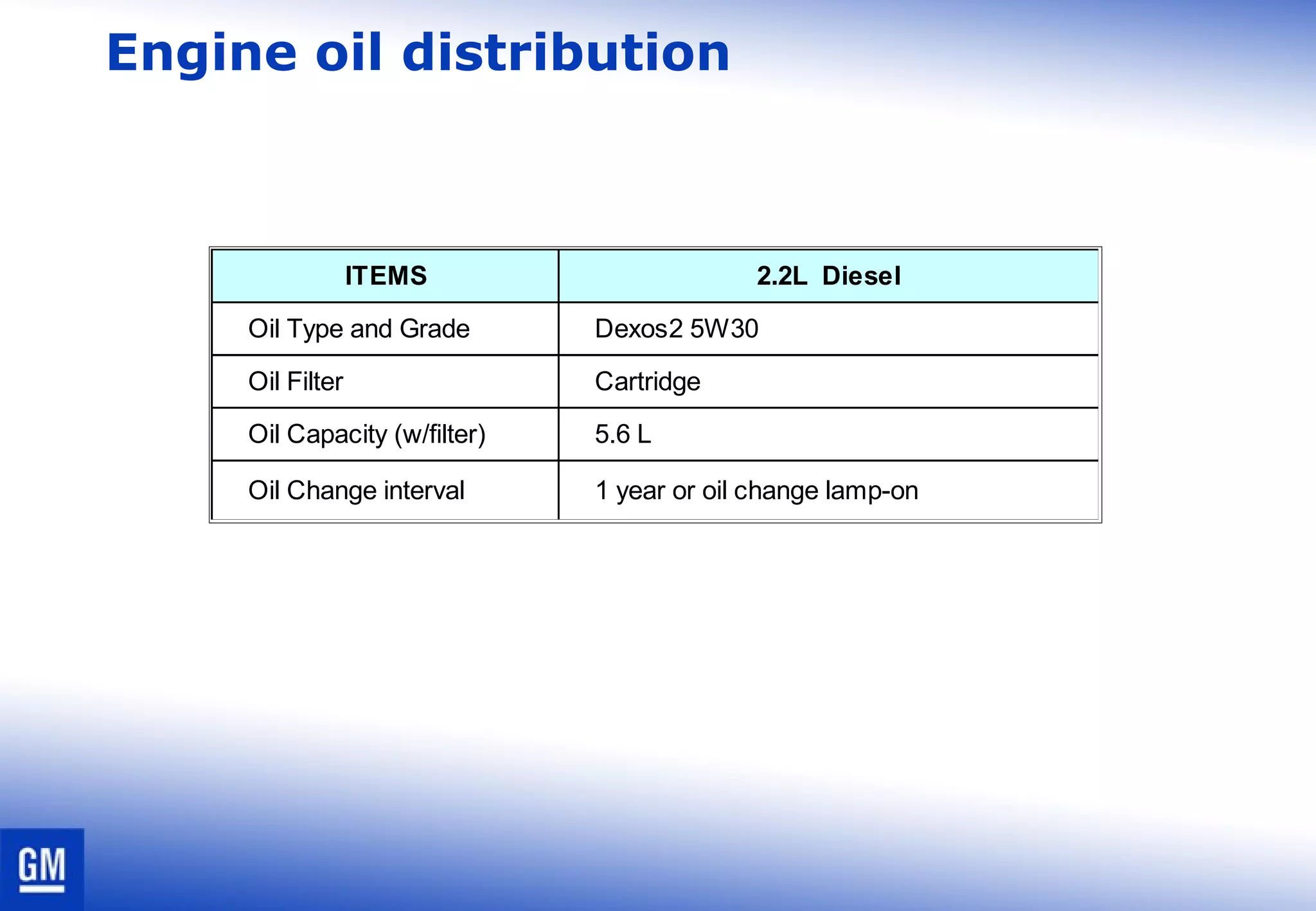
This document provides specifications for a 2.2L DOHC diesel engine. It includes details on the engine components like the cylinder head, block, pistons, crankshaft and camshaft. It also describes the engine systems including the timing chain, fuel delivery common rail system, turbocharger and variable geometry components, cooling system and lubrication system.
3. Spesifikasi Mesin
2.2L DOHC-Diesel
4 Cylinder(In-Line)
16.3 : 1
725
Roller Finger Follower
Hydraulic Lash Adjustment
Chain Drive
Compression ignition system
1-3-4-2
Ignition
Bore x Stroke (mm)
Displacement (cc)
Turbo Charger
Valve Lash Adjustment
Type
Ignition sequence
Max Combustion Peak
Pressure
Idle RPM
APPLICATION
Engine
General
Engine type
Timing Drive
Max Power (hp/RPM)
Max Torque (Nm/RPM)
Compression Ratio
Cam Follower
4. Engine specifications
2.2L DOHC-Diesel
Electric motor in fuel tank
Depth Media
165 ~215(at 4.5 bar)
4.15 ~5.35
Common rail
3 cylinder radial plunger
695 ㎣ / rev
Max 1400 bar
Max 1400 bar
Cartridge
50 L
Low
pressure
pump
Pump type
High
pressure
pump
Pump type
Fuel pressure (bar)
Injector pressure (bar)
APPLICATION
Filter type
Displacement (㎣)
Fuel Delivery
Filter type
Displacement (ℓ /H)
Fuel pressure (bar)
Filter Type
Fuel Tank Capacity
6. Cylinder head
Front side
(Timing Chain side)
Rear Side
(Transmisson side)
Exhaust side
Intake side
DOHC
4 valves per cylinder
roller type : finger followers
Drive vacuum pump
Drive high pressure fuel pump
made of aluminum
7. Cylinder block
made of grey iron with sand casting process
ties up with lower crankcase (Bedplate)
8. Piston & Road assembly
cast aluminum
a bowl type combustion chamber
Skirt of piston is coated with polymer
full-floating type piston
Fractured connecting rod
9. Crankshaft
made of high strength forged steel
5 main bearings
thrust bearing placed in the 3rd
crank bore
At the 6th of crankshaft arm, a crankshaft gear is hot
press fitted to drive a balance shaft
target wheel is assembled at the 8th
of crankshaft arm,
11. Valve train system
a
b
c
ed
f
g
h
i
j
k
l
DOHC
hydraulic lash adjuster
Intake cam shaft has a
chain sprocket with
integrated spur gear is
driven by chain
exhaust cam shaft driven
by scissors gear
Intake cam drives High
pressure fuel pump
Exhaust cam drives
mechanical vacuum pump
13. Engine oil distribution
ITEMS 2.2L Diesel
Oil Type and Grade Dexos2 5W30
Oil Filter Cartridge
Oil Capacity (w/filter) 5.6 L
Oil Change interval 1 year or oil change lamp-on
22. Timing chain adjustment(Installation)
1.Install the crankshaft sprocket
(1) with the timing chain mark at the 4
o’clock position.
Note: Ensure the crankshaft key
(2) is aligned with the
crankshaft timing mark (3).
Note: Ensure the camshaft
dowel (4) is at the 12
o’clock position and the
camshaft sprocket timing
marks are at the 12 an 3
o’clock positions as shown.
35. High pressure pump
Fuel inlet
Fuel outlet to rail
Fuel return to fuel tank
Fuel return from injectors
Inlet metering valve
Oldham Coupling
Cylinder
Cylinder
36. High pressure pump basic functioning
02.3-11
Showing 3 radial plungers, 2 plungers similar
37. High pressure pump
Part Item Specification Remarks
High pressure
pump
Type 2 cylinder plunger
Pump output
capacity
970 mm3
/rev
Output pressure
230 bar Idle
1800 bar Max. Power
Inlet Metering
Valve
Type Solenoid PWM control
Resistance 4.77 5.83 Ω∼
Operating
frequency
300 2000 Hz∼
42. Injector
Part Item Specification Remarks
Injector
Type Solenoid Multi injection type
Injection hole 8 holes
Operating temperature -30 120∼ ℃
Max. Injection pressure 1400 bar
Min. Injection pressure 150 bar
Normal Injection pressure 230 1400bar∼
Return pressure Pabs < 900 mb
Editor's Notes
Check for the emission regulation for your local area.
You can also use the graph underneath if your area uses Euro3 or Tier2 emission level.
If one looks carefully at the animation, one can see that a part of the diesel fuel is also injected during the intake stroke. This is wat we call a pre-pilot injection and is only done with the most advanced common rail systems.
Cold cranking can be a problem for diesel engines. When the air inside the cylinder is cold, the temperature at TDC might not be enough to reach the flame point of diesel fuel.If that happens, then you will need to install glow plugs. These glow plugs will heat up the air in order to auto-ignite the fuel.
e.g. 2.4L engine
Compression ratio: 9.6:1
Pressure at TDC: ~1000 kPa
Pilot injection will reduce considerably the amount of fuel injected during the ignition delay.
High pressure
Improved dispersion
Smaller drops
Electrical fuel pump
Fuel filter
High pressure pump
Fuel metering unit
Pressure regulator
Pressure accumulator
Pressure sensor
Injector
Engine control module
Fuel return damper
This cylinder head is DOHC (Double Over Head Camshaft) type and has two camshaft that open 4 valves per cylinder with the finger followers of roller type (end pivot type).
The camshaft gear is installed in front of camshaft and the vacuum pump and high pressure fuel pump are coupled in the rear of that. Because of the cam follower of the hydraulic type, it doesn&apos;t need to adjust of valve clearance.
The cylinder head is made of aluminum alloy, A356 with T7 air quench for better strength with light weight.
The intake port shape of the cylinder head is designed for increasing of high performance and swirl efficiency using swirl control valves and then this is maximized to diesel combustion efficiency.
The engine block is made of grey iron with sand casting process. The functions of the engine block can be categorized as support, locate, seal, transport, and provide clearance. It assists in locating components such as main bearings, crankshaft, and pistons. The engine block also provides for sealing at the piston rings, at the head gasket and contains oil and coolant inside the engine. In addition to containing fluids, the block must also transport pressurized oil and coolant while minimizing the pressure loss. Finally the engine block must provide clearance for the connecting rods, crankshaft, flexplate and provide access to the torque converter bolts.
The engine block ties up with lower crankcase (Bedplate) for crankshaft support. Lower crankcase provides BSM (Balance shaft module) and oil pan mounting surface on it’s bottom side.
The piston is cast aluminum included combustion chamber of a bowl type. Skirt of piston is coated with polymer to reduce friction and to enhance anti-scuffing. The piston assembly have 2 compression rings and 1 oil ring of 2-piece type loaded with coil spring. There is a piston pin of full-floating type between piston pin bore and rod pin bore and it is fixed by retainer located in both ends. The connecting rod is used fracture method to split rod and rod cap. The connecting rod and rod cap with bearings is positioned and fastened by bolts.
The crankshaft is made of high strength forged steel. It is located in between the engine block and the bed plate on 5 crankbores with main bearings, having bearing clearance for lubrication. Crankshaft axial end play is maintained with thrust bearing placed in the 3rd crankbore.
4 connecting rod big ends are assembled in pin journals of crankshaft with rod bearings to transfer reciprocating force of piston to rotating force of crankshaft.
At the 6th of crankshaft arm, a crankshaft gear is hot press fitted to drive a balance shaft module which runs by gears meshed. And at the 8th of crankshaft arm, target wheel is assembled with 3 bolts tightened to make a CPS(Crankshaft Position Sensor) read position signal of crankshaft.
The balance shaft module is a type of oil pump integration with suction pipe, running inside of oil pan. A drive gear of balance shaft is driven by crankshaft gear and drives a driven gear in balance shaft . A driven gear, connected to rotor of oil pump, offers power source to oil pump.
2 unbalance shafts are rotating to eliminate the vibration(2nd order shaking force) from reciprocating mass. And oil in the oil pan is delivered to oil path by oil pump.
Descriptions
The crankshaft pulley on the front of crankshaft drives the camshaft sprocket,
the water pump pulley and the high pressure pump sprocket using a timing
belt. Also, the automatic timing belt tensioner, is a double eccentric type,
assists the belt tension.
The timing belt idler which is a double row bearing type, to endure the high
load between the camshaft sprocket and the high pressure pump sprocket.
The function of the muffler is to reduce engine noise. It is made up of a series of perforated tubes and baffles to break up the sound waves and reflect them. It is made of Stainless Steel to protect the front muffler from corrosion.
The rear muffler is to reduce broad band engine exhaust noise. It is comprised of a series of perforated tubes and baffles to break up the sound waves and reflect them. The adopted dual muffler for C14X improves the efficiency to reduce flow noise.
It is made of Stainless Steel to protect the front muffler from corrosion.
1. Exhaust Manifold Heat Shield
2. Pre–Catalyst
3. Seal Ring
4. Clamp
5. DPF Pressure Sensor
6. DPF Pressure Sensor Hose
7. Exhaust Gas Temperature Sensor 2
8. Gasket
9. Rubber Hanger
10. Exhaust Gas Temperature Sensor 1
11. Exhaust Front Pipe Assembly
12. DPF (Diesel Particulate Filter) Assembly
13. DPF Heat Shield
14. Front Muffler Heat Shield
15. Front Muffler Assembly
16. Rear Muffler Assembly (Right–Side)
17. Rear Muffler Assembly (Left–Side)
1. Radiator
2. Charge Air Cooler
3. Main Cooling Fan Blade
4. Auxiliary Cooling Fan Blade
5. Main Cooling Fan Motor
6. Auxiliary Cooling Fan Motor
7. Cooling Fan Shroud
1. Water Pump
2. Water Pump Gasket
3. Thermostat Housing
4. Thermostat Gasket
5. Thermostat
6. Boost pressure & Temperature Sensor
7. Intake Manifold
8. Coolant Temperature Sensor
You can skip this slide if your participants have already enough diesel knowledge.
Give a demo to the participants of the injector diagnosis.
The injector is commanded by 45 Volts and its resistance is 0.2 Ω. If we use Ohms law to calculate the current, the current would be 90 Amps!!!! Of course this is impossible. Actually, the current should rise to 90 A, but never has the time to reach that value. After 0.1 ms the value has reached approximately 20 A.
Afterwards the voltage is kept at 10 Volts. This means that the 20 Amps is kept in the injector during another 0.2 ms.
Afterwards, the voltage is regulated in order to lower the current going through the injector.
(The injection time at idle speed takes approximately 0.4 ms)