Download as PDF, PPTX

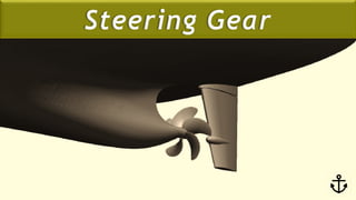


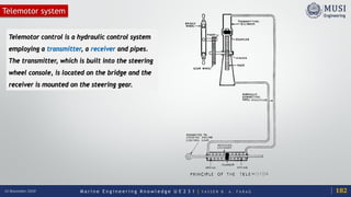


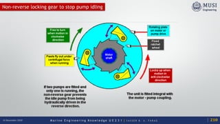


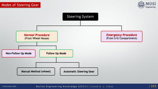


The document discusses the theory and operation of rudders in marine engineering, focusing on the forces generated by water flow around the rudder. It explains how these forces contribute to ship maneuverability, detailing various components such as lift and drag, and the mechanics of the steering gear system, including hydraulic and telemotor systems. Additionally, it covers the importance of constant pump operation in hydraulic systems for instantaneous response.


