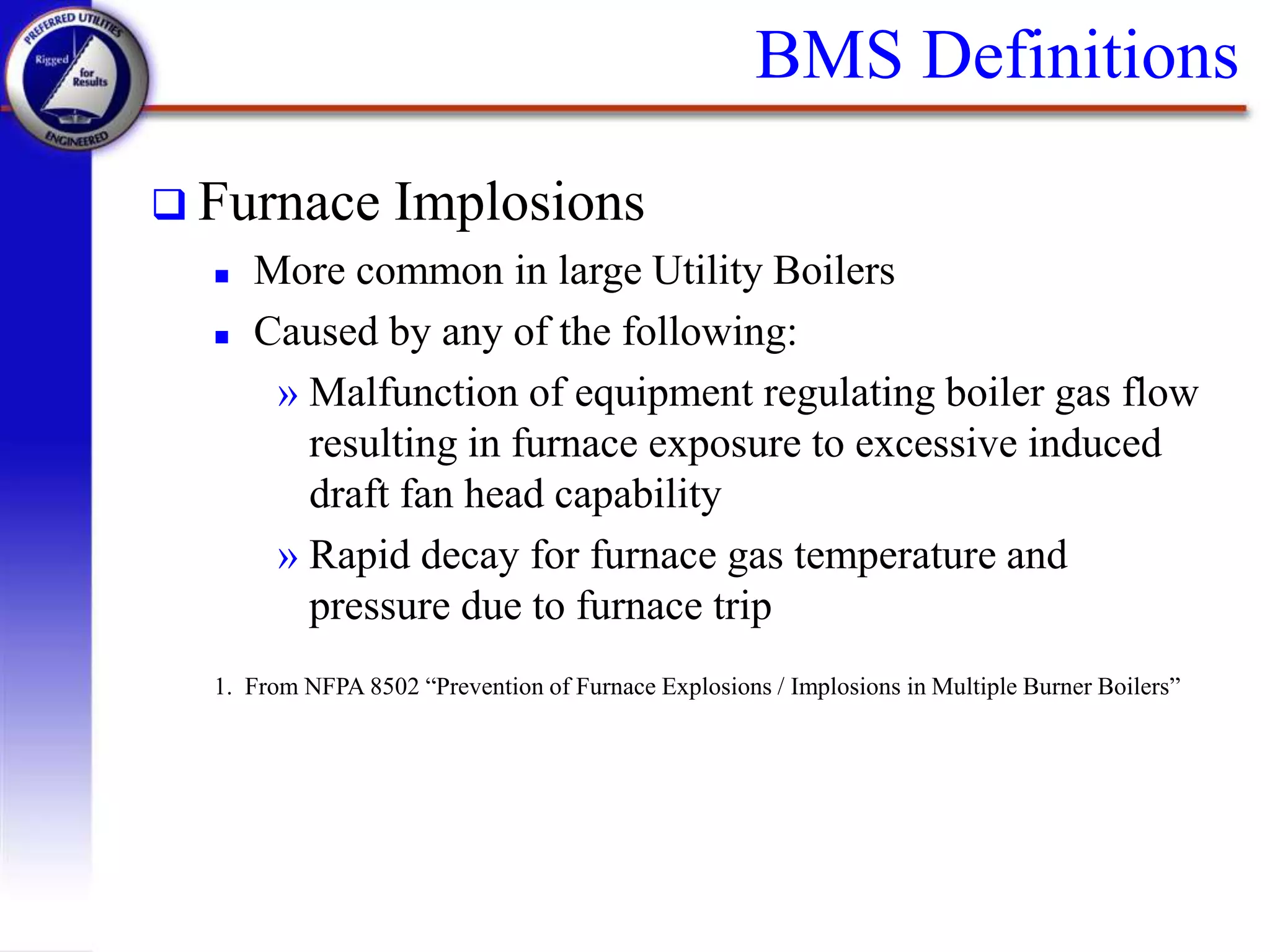
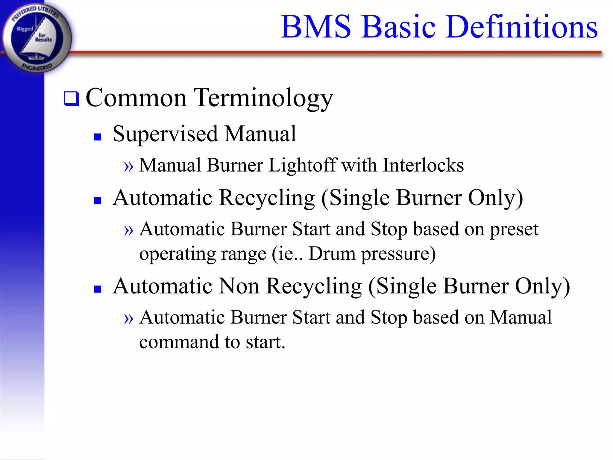
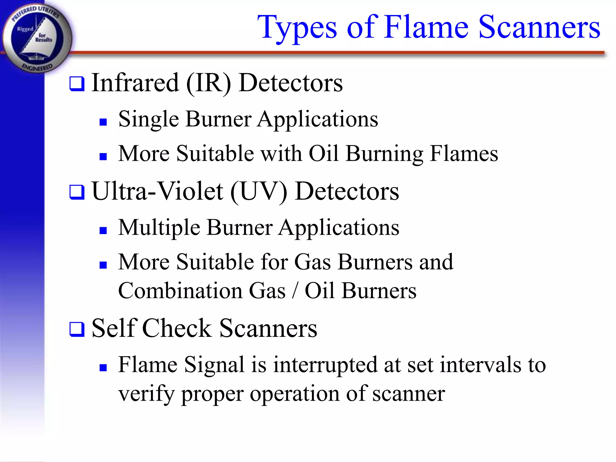
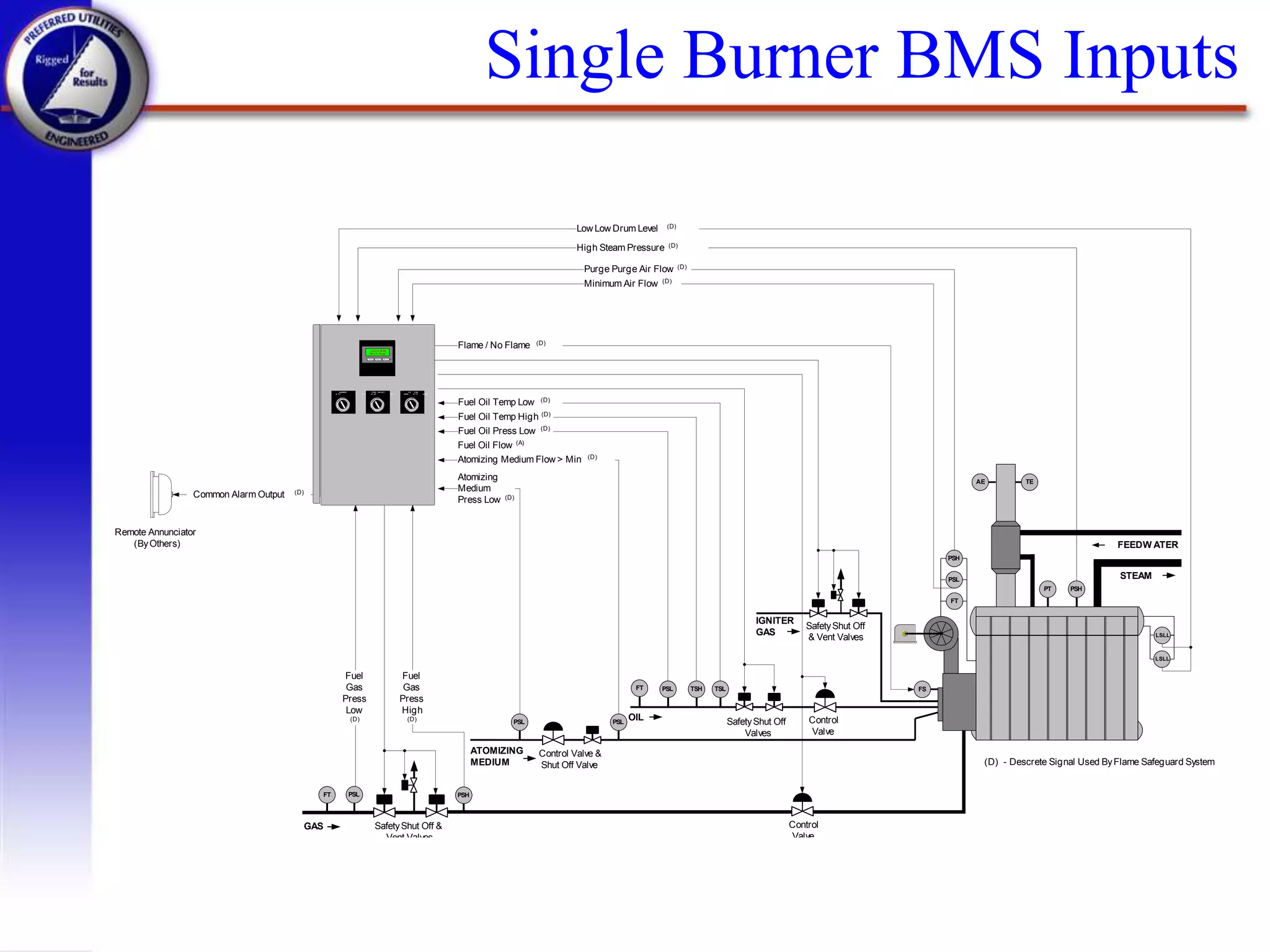
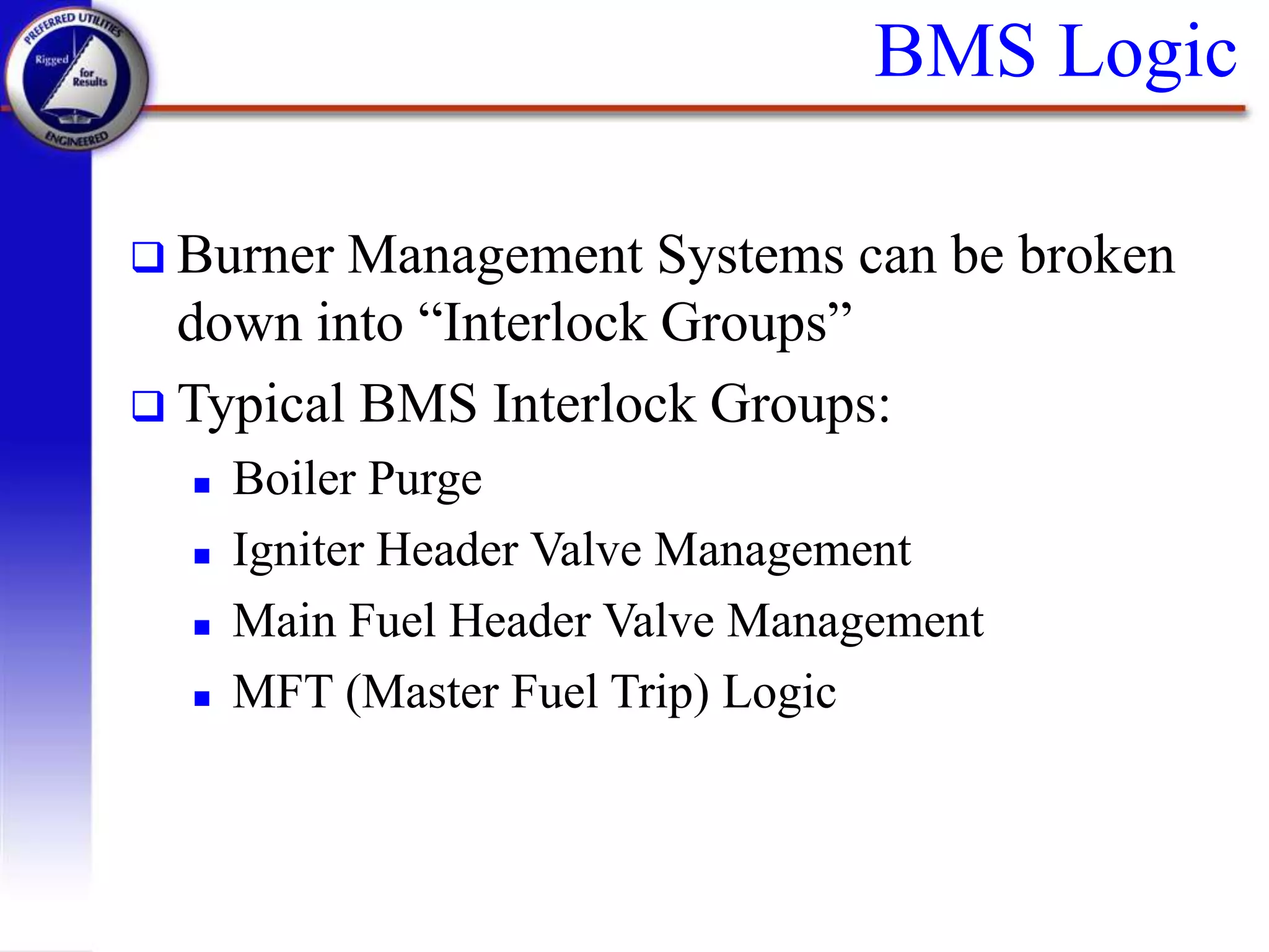
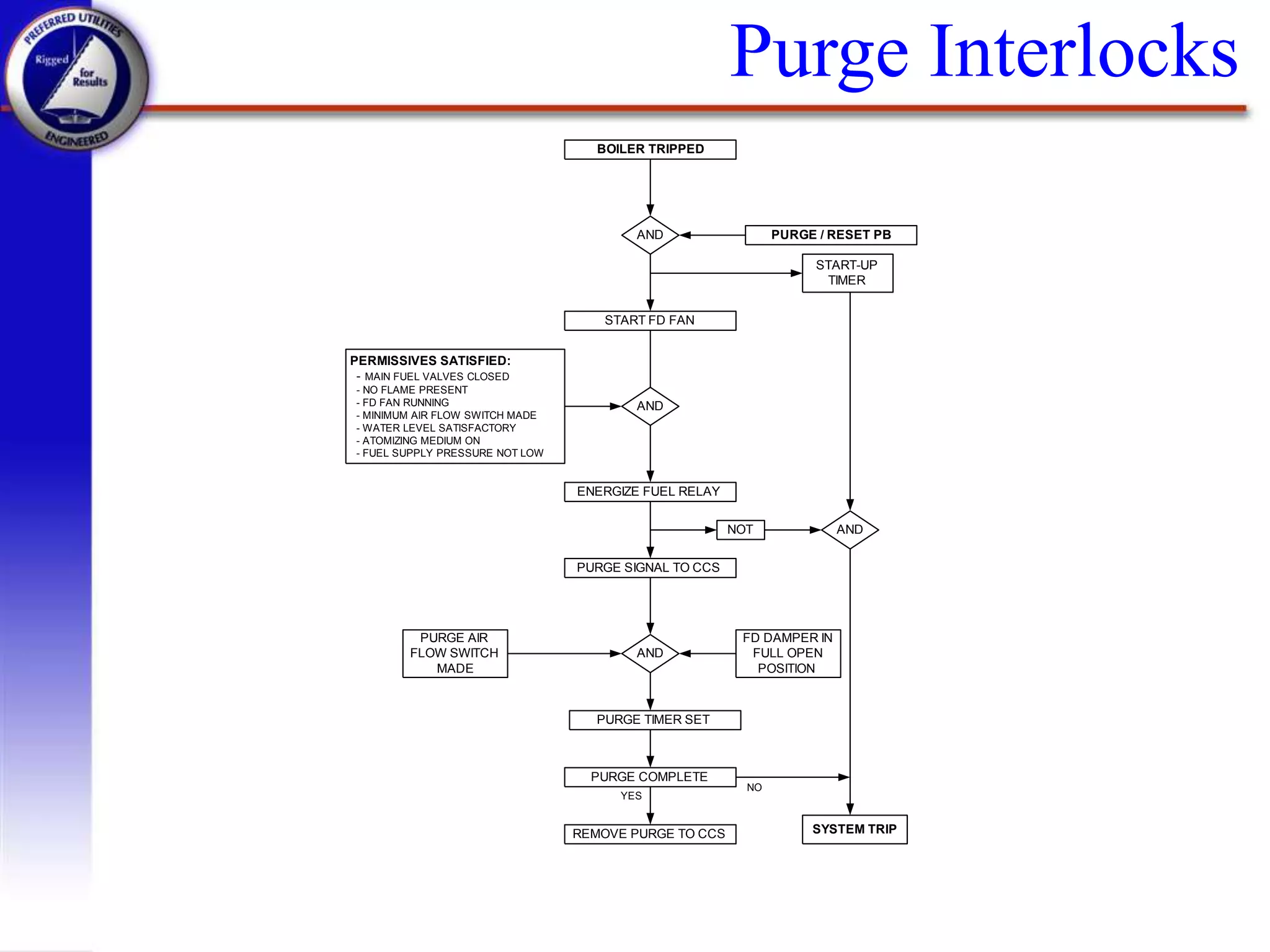
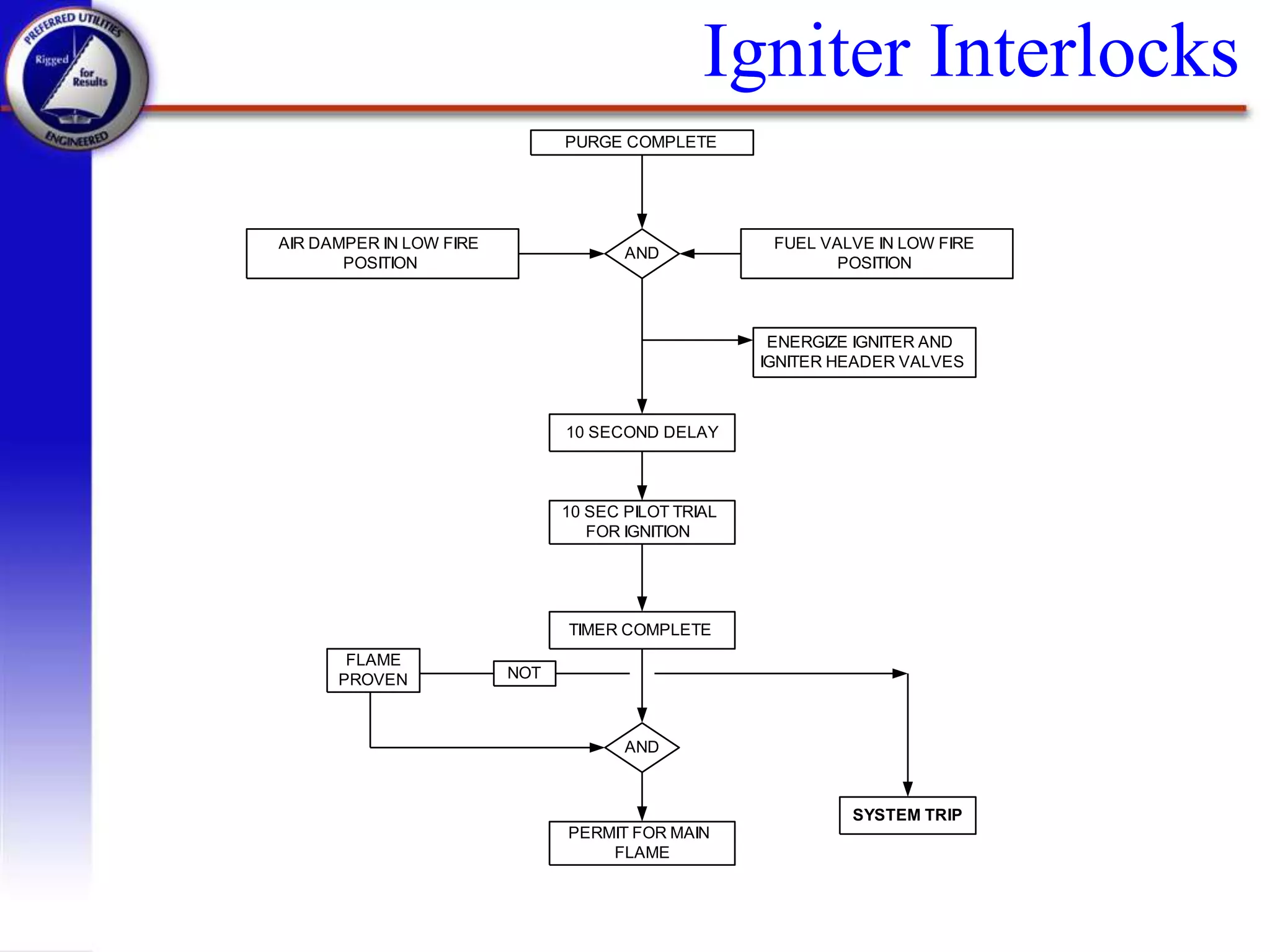
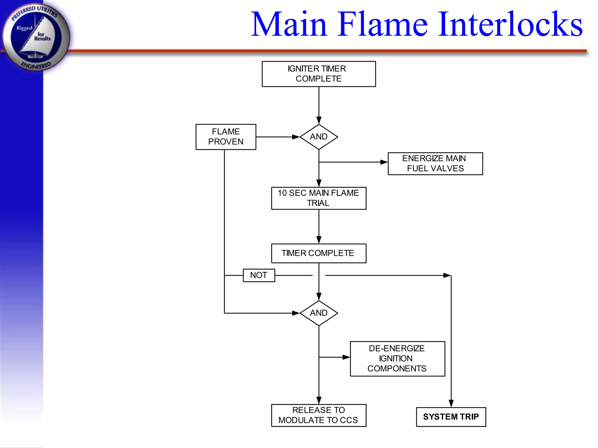
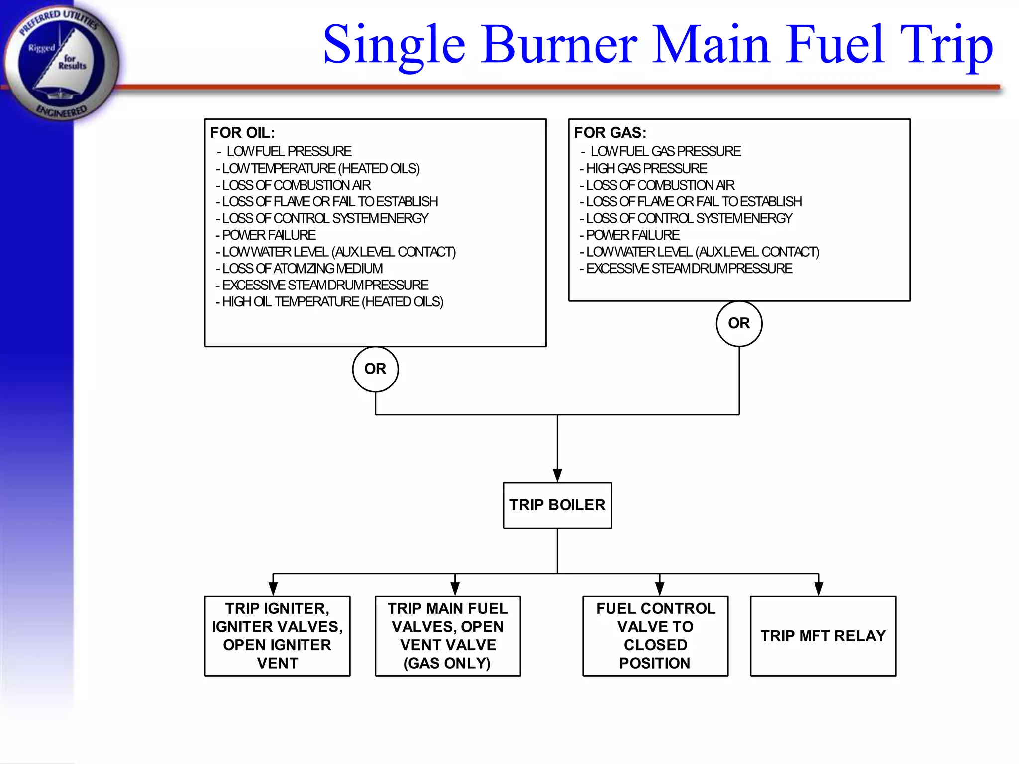
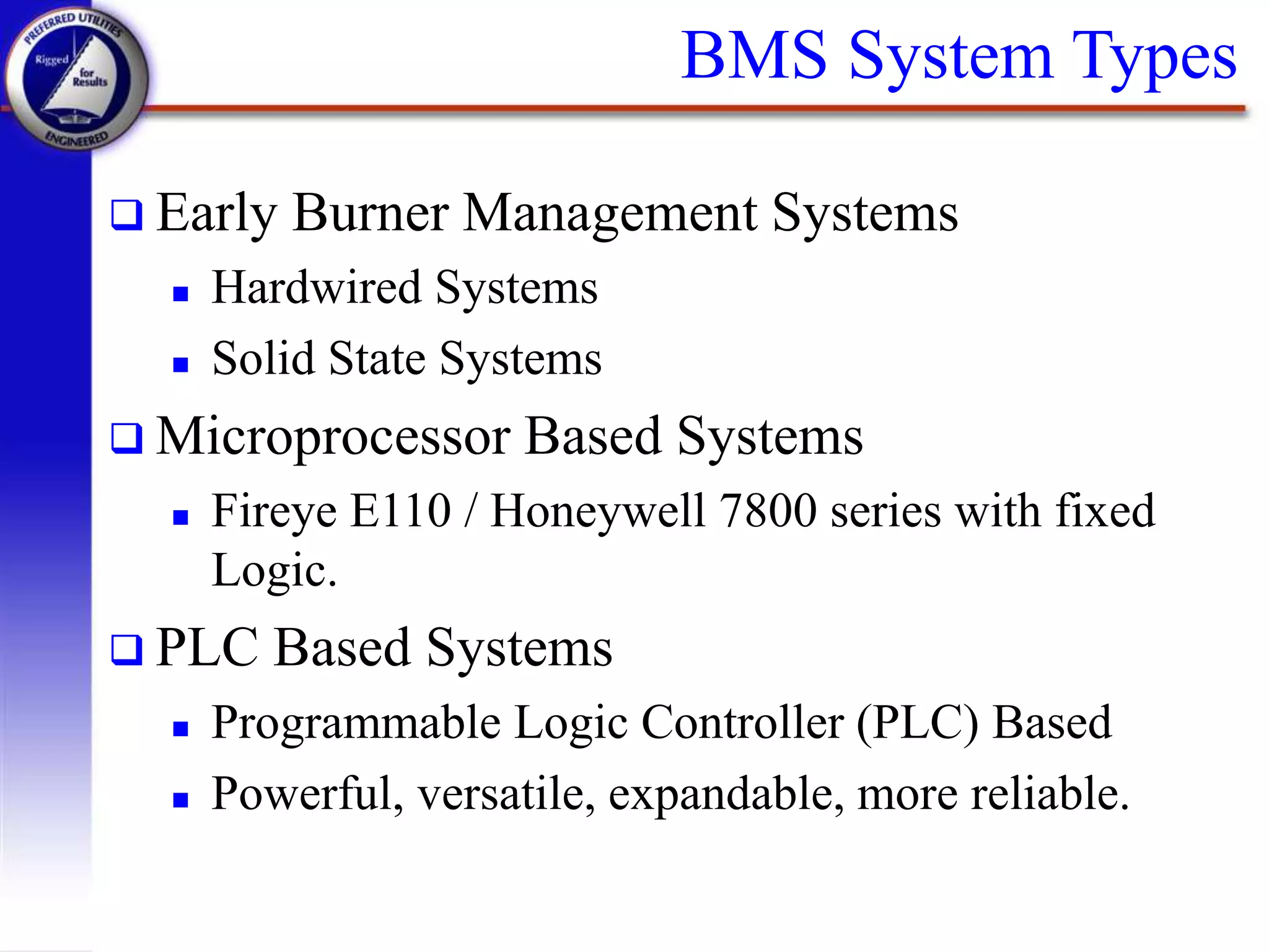
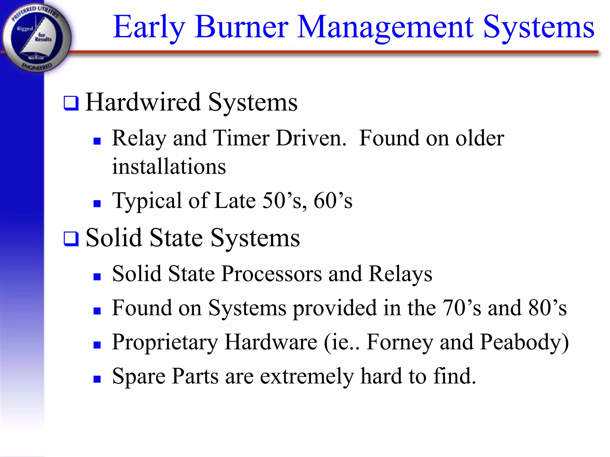
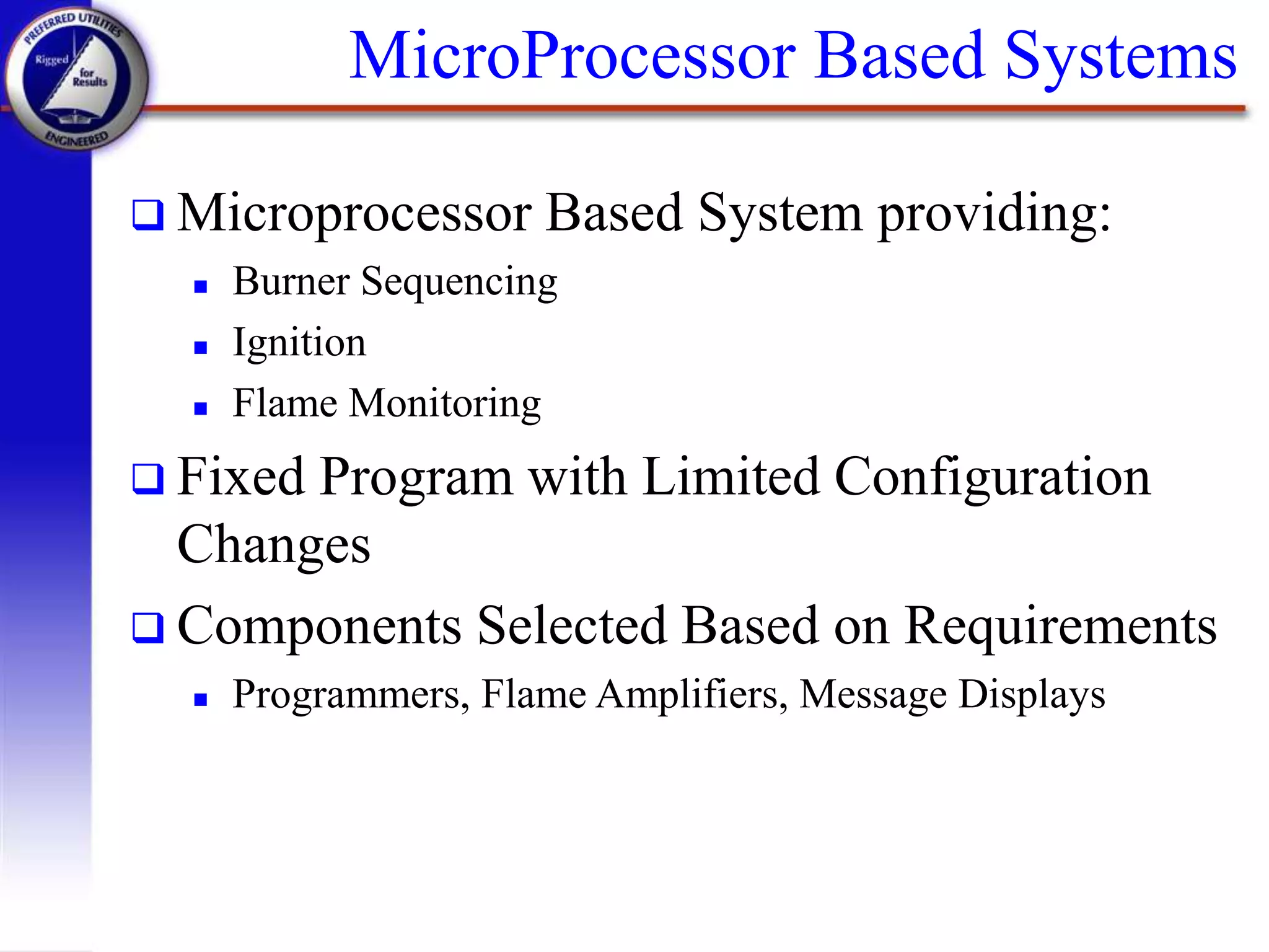
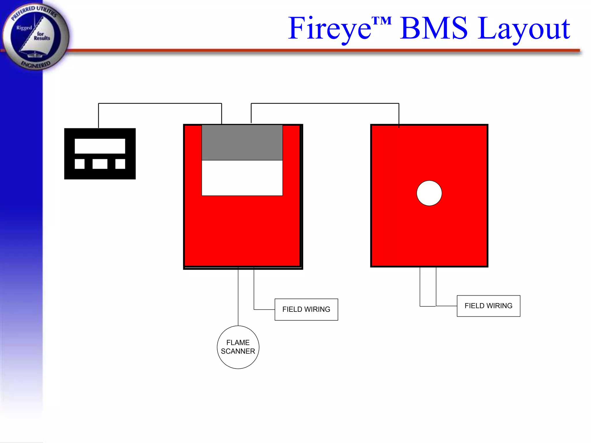
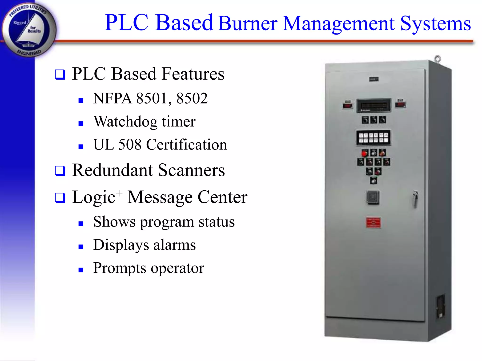
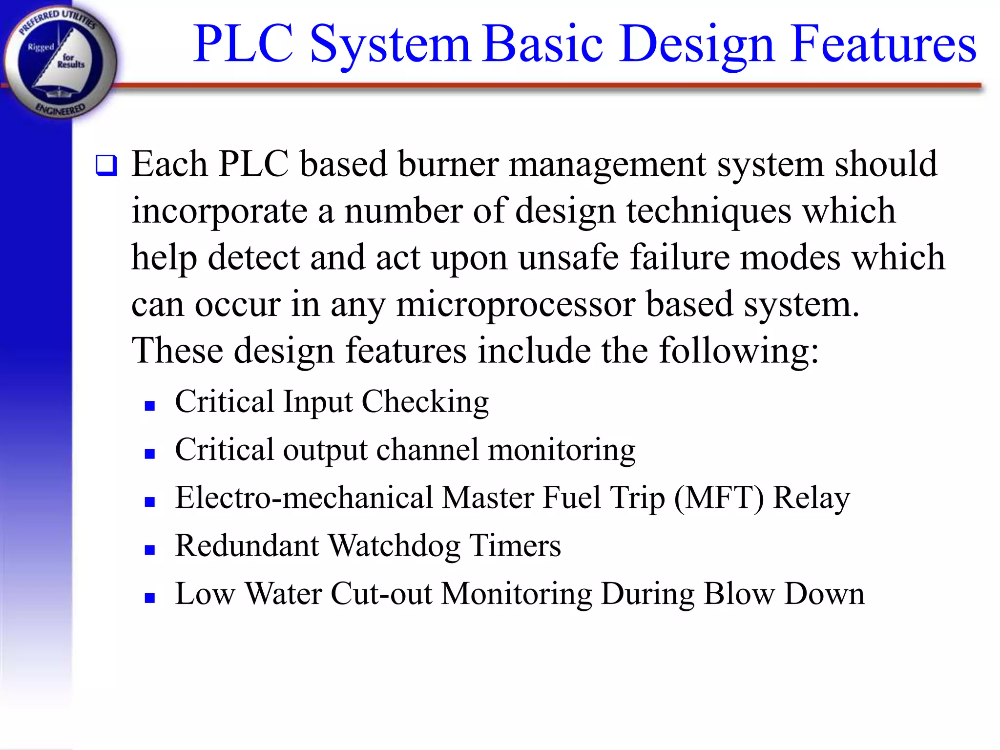
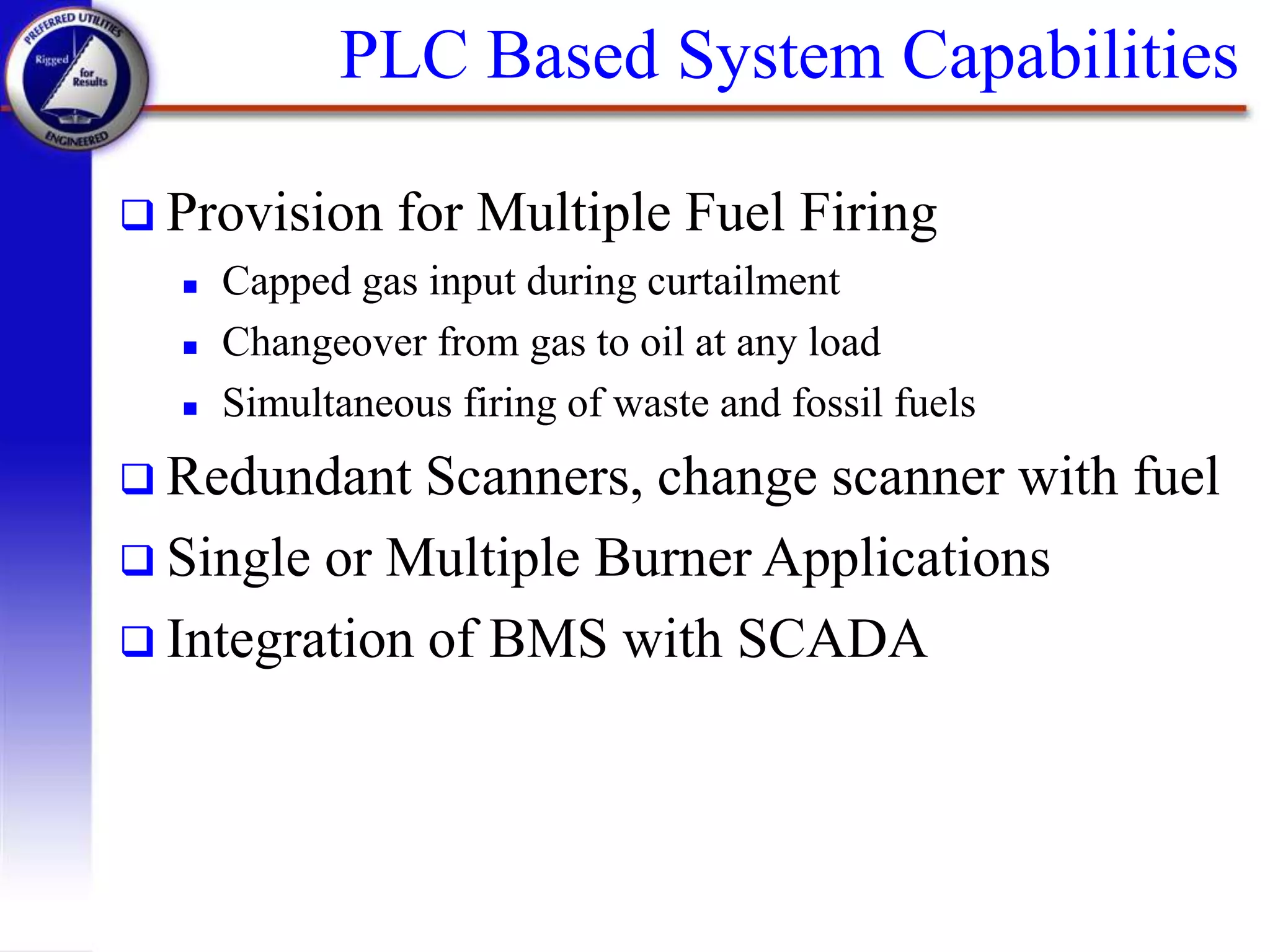
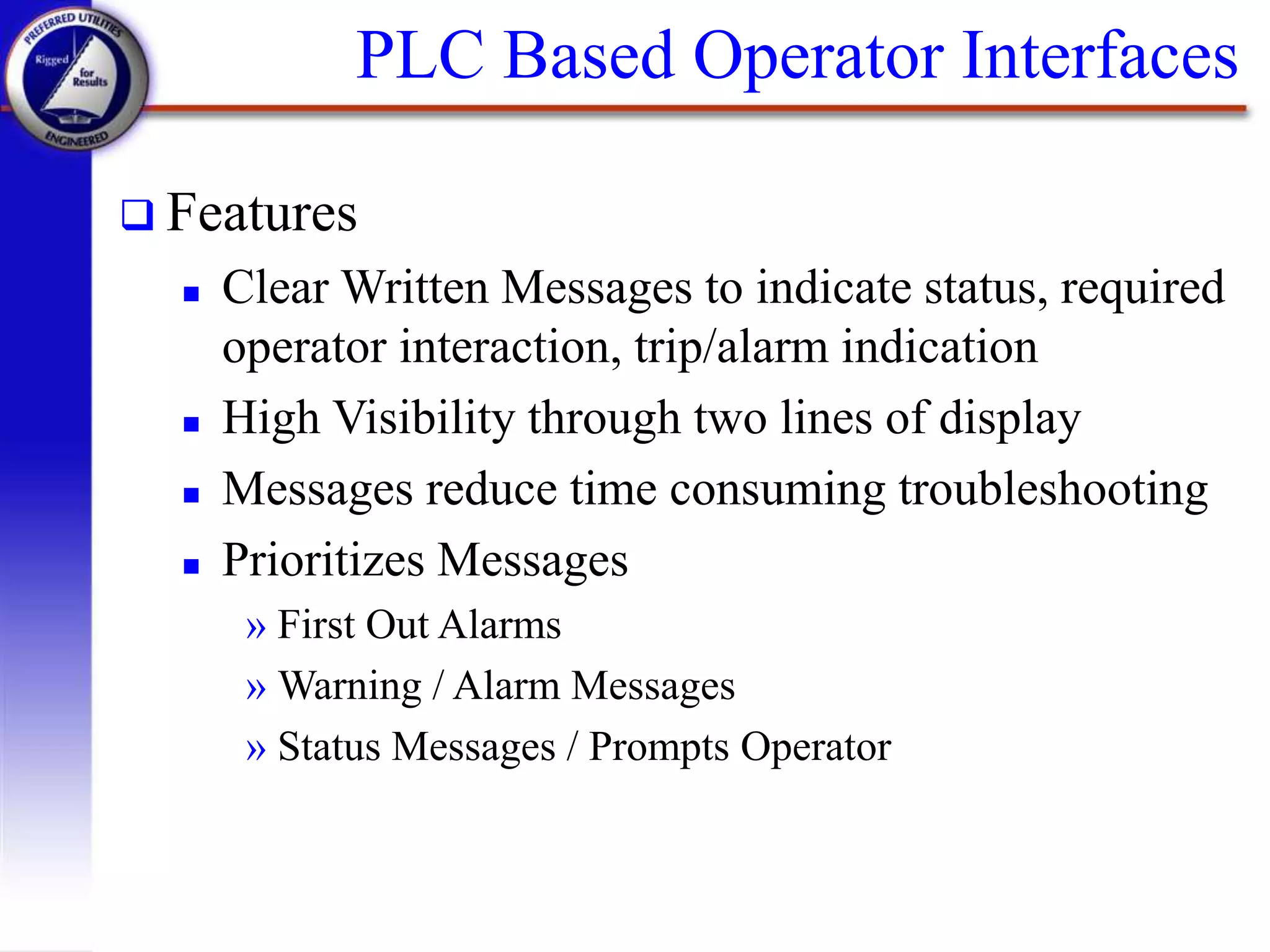
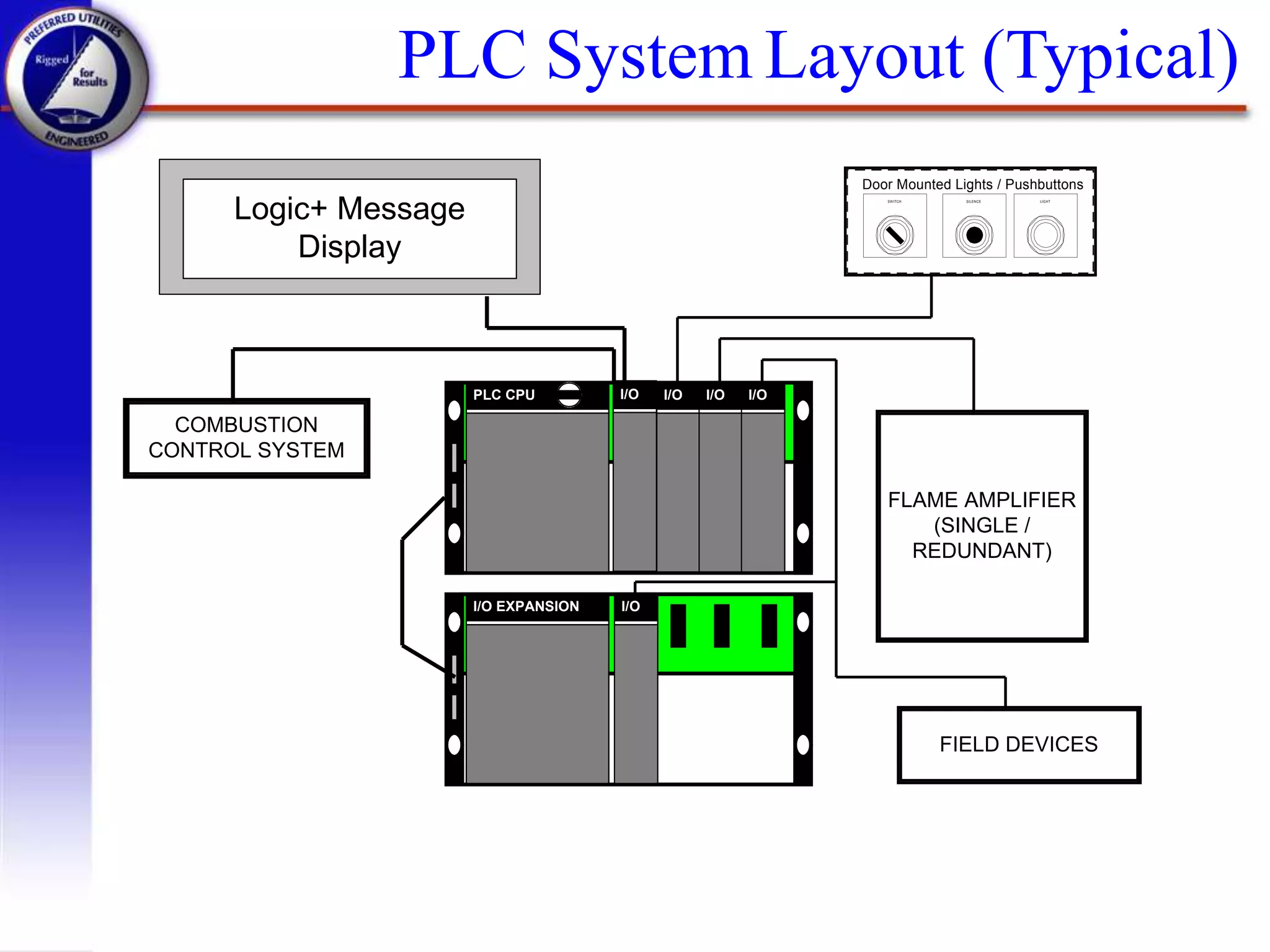
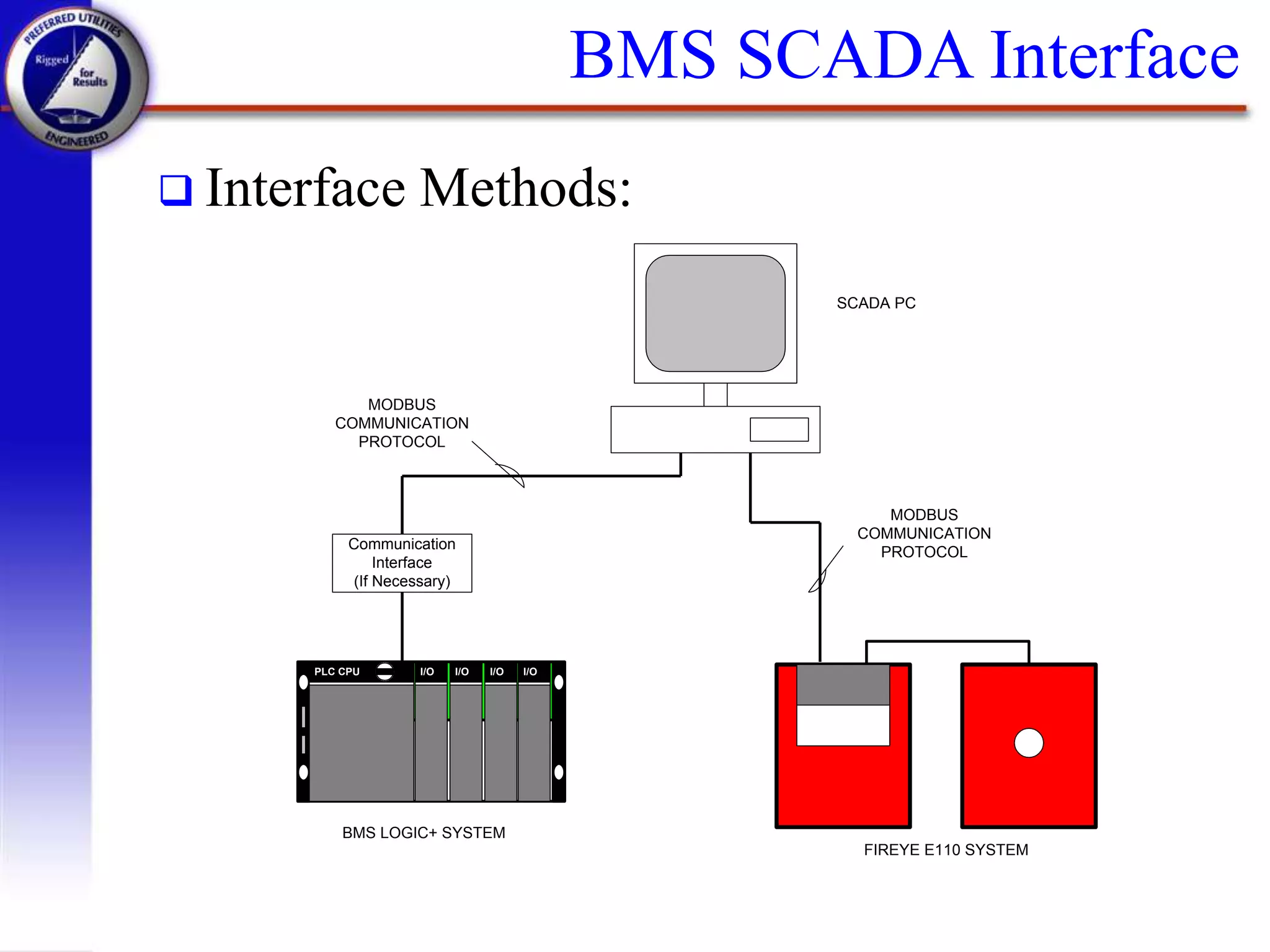
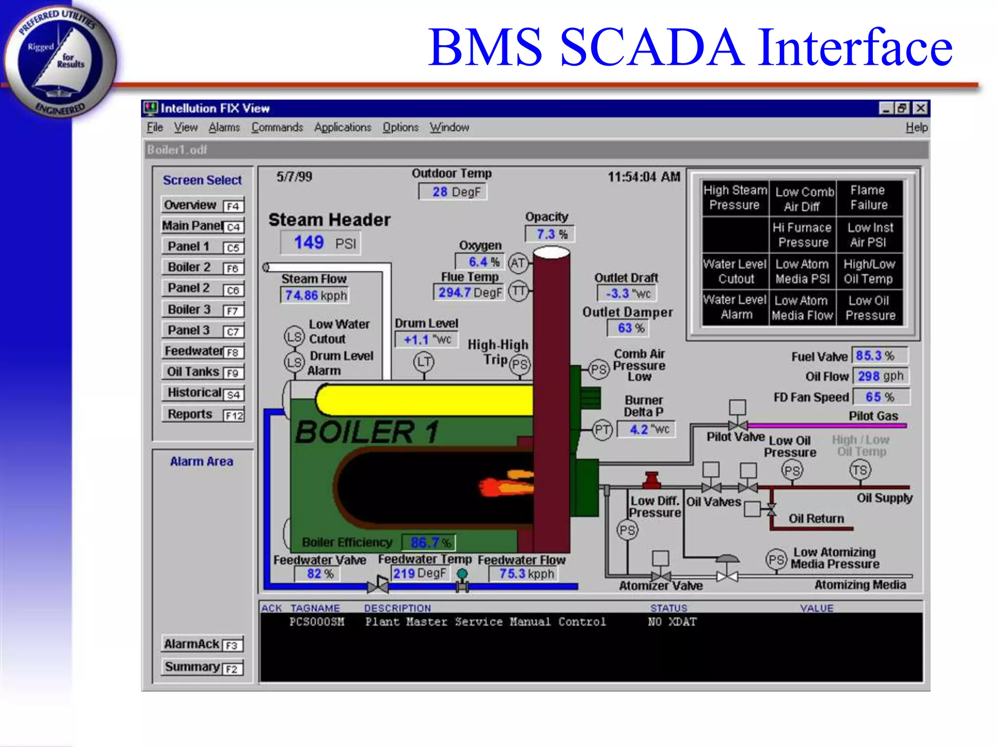
Preferred Utilities Manufacturing Corp.
Burner
Management Systems
A Technical Discussion
Preferred Utilities Manufacturing Corp.
 Introduction
 Burner Management System Objectives
 BMS Design Standards and Definitions
 BMS Logic
 BMS Strategies and Hardware
 Types of Burner Management Systems
 BMS Interface to SCADA Systems
 Summary
Introduction
..a starting point.
Burner Management
Systems..
Introduction
What is a BMS?
 A Burner Management System is defined as
the following:
 A Control System that is dedicated to boiler
safety, operator assistance in the starting and
stopping of fuel preparation and burning
equipment, and the prevention of mis-operation
of and damage to fuel preparation and fuel
burning equipment. 1
1. From NFPA 8501 “Standard for Single Burner Boiler Operation”
Burner Management Objectives
 Sequence burner through safe start-up
 Insure a complete pre-purge of boiler
 Supervise safety limits during operation
 Supervise the flame presence during
operation
 Sequence a safe shutdown at end of cycle
 Integrate with combustion control system
for proper fuel and air flows
BMS Design Standards
 Each Burner Management System should be
designed in accordance with the below listed
guidelines to control and monitor all sequences of
the start-up and shutdown of the burner
 National Fire Protection Association (NFPA 8501
/8502 or others)
 Industrial Risk Insurers (IRI)
 Factory Mutual loss prevention guidelines
 Each burner management system should be
designed to accomplish a safety shutdown in the
event of an unsafe condition. (FAIL SAFE)
BMS Design Standards
 U.S. National Fire Protection Association
(NFPA)
 Governs safety system design on virtually all boilers
(regardless of the process to be used to combust the
fuel)
 Requires the separation of the Burner Management
System from any other control system
 Requires the use of a hardwired backup tripping scheme
for microprocessor based systems
 Requires that a single failure NOT prevent an
appropriate shutdown
 Factory Mutual loss prevention guidelines.
NFPA 8501
 NFPA 8501 Standard for Single Burner
Boiler Operation
 Single Burner Boilers with fuel input greater than 12.5
mBTU/Hr (Approx. 250 BHP)
 Single Fuel or Combination of Fuels (Common being
Natural Gas / No.2 Oil / No. 6 Oil)
 Simultaneous Firing
NFPA 8502
 NFPA 8502 Standard for Prevention of
Furnace Explosions / Implosions in Multiple
Burner Boilers
 Multiple Burner Boilers with fuel input greater than
12.5 mBTU/Hr
 Single Fuel or Combination of Fuels including
Pulverized Coal
 Emphasis on implosion protection (larger boilers with
induced draft systems)
BMS Definitions
 Furnace Explosions
 “Ignition of accumulated combustible mixture within
the confined space of a furnace or associated boiler
passes, ducts, and fans that convey gases of combustion
to the stack”1
 Magnitude and intensity of explosion depends on
relative quantity of combustibles and the proportion of
air at the time of ignition
1. From NFPA 8502 “Prevention of Furnace Explosions / Implosions in Multiple Burner Boilers”
BMS Definitions
 Furnace Explosions can occur with any or a
combination of the following:1
 Momentary loss of flame followed by delayed re-
ignition
 Fuel leakage into an idle furnace ignited by source of
ignition (such as a welding spark)
 Repeated Light-off attempts without proper purging
 Loss of Flame on one Burner while others are in
operation
 Complete Furnace Flame-out followed by an attempt to
light a burner
1. From NFPA 8502 “Prevention of Furnace Explosions / Implosions in Multiple Burner Boilers”
BMS Definitions
 Furnace Implosions
 More common in large Utility Boilers
 Caused by any of the following:
» Malfunction of equipment regulating boiler gas flow
resulting in furnace exposure to excessive induced
draft fan head capability
» Rapid decay for furnace gas temperature and
pressure due to furnace trip
1. From NFPA 8502 “Prevention of Furnace Explosions / Implosions in Multiple Burner Boilers”
BMS Basic Definitions
 Common Terminology
 Supervised Manual
» Manual Burner Lightoff with Interlocks
 Automatic Recycling (Single Burner Only)
» Automatic Burner Start and Stop based on preset
operating range (ie.. Drum pressure)
 Automatic Non Recycling (Single Burner Only)
» Automatic Burner Start and Stop based on Manual
command to start.
Types of Flame Scanners
 Infrared (IR) Detectors
 Single Burner Applications
 More Suitable with Oil Burning Flames
 Ultra-Violet (UV) Detectors
 Multiple Burner Applications
 More Suitable for Gas Burners and
Combination Gas / Oil Burners
 Self Check Scanners
 Flame Signal is interrupted at set intervals to
verify proper operation of scanner
Single Burner BMS Inputs
OIL
GAS
STEAM
FEEDW ATER
PSL
TSL
TSH
PSL
High Steam Pressure (D)
Low Low Drum Level (D)
PSL PSH
PSL
ATOMIZING
MEDIUM
Fuel
Gas
Press
Low
(D)
Fuel
Gas
Press
High
(D)
FT
FT
Atomizing
Medium
Press Low (D)
Fuel Oil Flow (A)
Fuel Oil Temp High (D)
Fuel Oil Temp Low (D)
Atomizing Medium Flow > Min (D)
Fuel Oil Press Low (D)
PSH
PSL
FT
PSH
PT
LSLL
LSLL
Purge Purge Air Flow (D)
Minimum Air Flow (D)
AE TE
(D) - Descrete Signal Used ByFlame Safeguard System
Common Alarm Output (D)
Remote Annunciator
(ByOthers)
SafetyShut Off &
Vent Valves
Control Valve &
Shut Off Valve
SafetyShut Off
Valves
Control
Valve
Control
Valve
SafetyShut Off
& Vent Valves
IGNITER
GAS
Flame / No Flame (D)
FS
FD FAN
HAND O FF AUTO
Li mi t s M ade
H
ol d t o Purge
S C R L M O D E
R E S E T
FUEL SELECT
G AS O I L
BURNER
O FF O N
BMS Logic
 Burner Management Systems can be broken
down into “Interlock Groups”
 Typical BMS Interlock Groups:
 Boiler Purge
 Igniter Header Valve Management
 Main Fuel Header Valve Management
 MFT (Master Fuel Trip) Logic
Purge Interlocks
BOILER TRIPPED
AND PURGE / RESET PB
START FD FAN
AND
PERMISSIVES SATISFIED:
- MAIN FUEL VALVES CLOSED
- NO FLAME PRESENT
- FD FAN RUNNING
- MINIMUM AIR FLOW SWITCH MADE
- WATER LEVEL SATISFACTORY
- ATOMIZING MEDIUM ON
- FUEL SUPPLY PRESSURE NOT LOW
ENERGIZE FUEL RELAY
PURGE SIGNAL TO CCS
NOT AND
START-UP
TIMER
AND
PURGE AIR
FLOW SWITCH
MADE
FD DAMPER IN
FULL OPEN
POSITION
PURGE TIMER SET
PURGE COMPLETE
REMOVE PURGE TO CCS SYSTEM TRIP
YES
NO
Igniter Interlocks
AND
ENERGIZE IGNITER AND
IGNITER HEADER VALVES
NOT
SYSTEM TRIP
PURGE COMPLETE
AIR DAMPER IN LOW FIRE
POSITION
FUEL VALVE IN LOW FIRE
POSITION
10 SECOND DELAY
FLAME
PROVEN
10 SEC PILOT TRIAL
FOR IGNITION
TIMER COMPLETE
AND
PERMIT FOR MAIN
FLAME
Main Flame Interlocks
AND
NOT
SYSTEM TRIP
IGNITER TIMER
COMPLETE
FLAME
PROVEN
10 SEC MAIN FLAME
TRIAL
TIMER COMPLETE
AND
RELEASE TO
MODULATE TO CCS
ENERGIZE MAIN
FUEL VALVES
DE-ENERGIZE
IGNITION
COMPONENTS
Single Burner Main Fuel Trip
FOR OIL:
- LOWFUELPRESSURE
-LOWTEM
PERATURE(HEATEDOILS)
-LOSSOFCOM
BUSTIONAIR
-LOSSOFFLAMEORFAILTOESTABLISH
-LOSSOFCONTROLSYSTEMENERGY
- POWERFAILURE
- LOWWATERLEVEL(AUXLEVELCONTACT)
- LOSSOFATOM
IZINGM
EDIUM
- EXCESSIVESTEAMDRUMPRESSURE
- HIGHOILTEM
PERATURE(HEATEDOILS)
TRIP BOILER
FOR GAS:
- LOWFUELGASPRESSURE
- HIGHGASPRESSURE
-LOSSOFCOM
BUSTIONAIR
-LOSSOFFLAMEORFAILTOESTABLISH
-LOSSOFCONTROLSYSTEMENERGY
- POWERFAILURE
- LOWWATERLEVEL(AUXLEVELCONTACT)
- EXCESSIVESTEAMDRUMPRESSURE
OR
OR
TRIP IGNITER,
IGNITER VALVES,
OPEN IGNITER
VENT
TRIP MAIN FUEL
VALVES, OPEN
VENT VALVE
(GAS ONLY)
FUEL CONTROL
VALVE TO
CLOSED
POSITION
TRIP MFT RELAY
BMS System Types
 Early Burner Management Systems
 Hardwired Systems
 Solid State Systems
 Microprocessor Based Systems
 Fireye E110 / Honeywell 7800 series with fixed
Logic.
 PLC Based Systems
 Programmable Logic Controller (PLC) Based
 Powerful, versatile, expandable, more reliable.
Early Burner Management Systems
 Hardwired Systems
 Relay and Timer Driven. Found on older
installations
 Typical of Late 50’s, 60’s
 Solid State Systems
 Solid State Processors and Relays
 Found on Systems provided in the 70’s and 80’s
 Proprietary Hardware (ie.. Forney and Peabody)
 Spare Parts are extremely hard to find.
MicroProcessor Based Systems
 Microprocessor Based System providing:
 Burner Sequencing
 Ignition
 Flame Monitoring
 Fixed Program with Limited Configuration
Changes
 Components Selected Based on Requirements
 Programmers, Flame Amplifiers, Message Displays
FLAME
SCANNER
FIELD WIRING
Fireye™ BMS Layout
AUTOMATIC PRIMARY SAFETY CONTROL
AMPLIFIER
EP PROGRAMMER
FIELD WIRING
MicroProcessor Capabilities
 Simple, Cost Effective
 Features
 Selectable Flame Amplifiers / Scanners
 Remote Display
 Remote Data Communications via Modbus Port
 Modernization kits are available to integrate with older
systems
 Spare Parts Normally Readily Available
When These Systems are Used
 “Simple” Boiler Installations
 Packaged Firetube / Watertube Boilers (Steam /
Hot Water)
 Single Burner
 One Fuel at a Time
 No Flue Gas Re-Circulation
 Upgrades from Previous MicroProcessor Based
Systems
PLC Based Burner Management Systems
 PLC Based Features
 NFPA 8501, 8502
 Watchdog timer
 UL 508 Certification
 Redundant Scanners
 Logic+ Message Center
 Shows program status
 Displays alarms
 Prompts operator
 Each PLC based burner management system should
incorporate a number of design techniques which
help detect and act upon unsafe failure modes which
can occur in any microprocessor based system.
These design features include the following:
 Critical Input Checking
 Critical output channel monitoring
 Electro-mechanical Master Fuel Trip (MFT) Relay
 Redundant Watchdog Timers
 Low Water Cut-out Monitoring During Blow Down
PLC System Basic Design Features
PLC Based System Capabilities
 Provision for Multiple Fuel Firing
 Capped gas input during curtailment
 Changeover from gas to oil at any load
 Simultaneous firing of waste and fossil fuels
 Redundant Scanners, change scanner with fuel
 Single or Multiple Burner Applications
 Integration of BMS with SCADA
PLC Based Operator Interfaces
 Features
 Clear Written Messages to indicate status, required
operator interaction, trip/alarm indication
 High Visibility through two lines of display
 Messages reduce time consuming troubleshooting
 Prioritizes Messages
» First Out Alarms
» Warning / Alarm Messages
» Status Messages / Prompts Operator
PLC System Layout (Typical)
Logic+ Message
Display
SWITCH SILENCE LIGHT
Door Mounted Lights / Pushbuttons
FLAME AMPLIFIER
(SINGLE /
REDUNDANT)
FIELD DEVICES
PLC CPU I/O I/O I/O I/O
I/O EXPANSION I/O
COMBUSTION
CONTROL SYSTEM
Benefits of PLC Based Systems
 Flexibility / Reliability
 Programming Software allows changes to
system
 Choice of PLCs
 GE / Modicon / Allen Bradley / Koyo
 Choice of Flame Scanners
 PPC / Fireye / Honeywell / Iris / Coen
 Application Specific
 Quantity of Burners / Fuels is not restricted
When to Use PLC Based Systems
 “Complex” Boiler Installations
 Larger Packaged Units / Field Erected Units
 Multiple Burners
 Multiple Fuels, On-line Fuel Changeovers
 Flue Gas Re-Circulation
 Replace Existing Relay Logic Systems
 Requirement to maintain consistent control
platform (spare parts, etc..)
BMS SCADA Interface
 BMS Systems can be integrated into a
SCADA System
 Allows Remote Monitoring of Flame Status
 Allows Remote Control of BMS
 Events (ie.. Burner trip) can be routed to
Historical Portion of SCADA for fault
evaluation
 Burner Operation can be trended over time
BMS SCADA Interface
 Interface Methods:
PLC CPU I/O I/O I/O I/O
Communication
Interface
(If Necessary)
MODBUS
COMMUNICATION
PROTOCOL
MODBUS
COMMUNICATION
PROTOCOL
BMS LOGIC+ SYSTEM
SCADA PC
FIREYE E110 SYSTEM
BMS SCADA Interface
Summary
 Benefits Associated with New Burner
Management Systems
 Help Improve plant safety
 Help qualify for reduced insurance cost
 Reduce Startup and Down Time with
comprehensive alarming and diagnostics
Summary
Review of Topics Discussed
 Objectives of Burner Management Systems
 BMS Design Considerations
 Basic BMS Logic
 Types of Burner Management Systems
 How BMS Systems can be integrated with
Plant Wide SCADA Systems
Preferred Utilities Manufacturing Corp
For further information, contact...
Preferred Utilities Manufacturing Corporation
31-35 South St. • Danbury • CT
T: (203) 743-6741 • F: (203) 798-7313
www.preferred-mfg.com

Burner management-systems-a-technical-discussion-ppt

  • 1.
    Preferred Utilities ManufacturingCorp. Burner Management Systems A Technical Discussion
  • 2.
    Preferred Utilities ManufacturingCorp.  Introduction  Burner Management System Objectives  BMS Design Standards and Definitions  BMS Logic  BMS Strategies and Hardware  Types of Burner Management Systems  BMS Interface to SCADA Systems  Summary
  • 3.
  • 4.
    Introduction What is aBMS?  A Burner Management System is defined as the following:  A Control System that is dedicated to boiler safety, operator assistance in the starting and stopping of fuel preparation and burning equipment, and the prevention of mis-operation of and damage to fuel preparation and fuel burning equipment. 1 1. From NFPA 8501 “Standard for Single Burner Boiler Operation”
  • 5.
    Burner Management Objectives Sequence burner through safe start-up  Insure a complete pre-purge of boiler  Supervise safety limits during operation  Supervise the flame presence during operation  Sequence a safe shutdown at end of cycle  Integrate with combustion control system for proper fuel and air flows
  • 6.
    BMS Design Standards Each Burner Management System should be designed in accordance with the below listed guidelines to control and monitor all sequences of the start-up and shutdown of the burner  National Fire Protection Association (NFPA 8501 /8502 or others)  Industrial Risk Insurers (IRI)  Factory Mutual loss prevention guidelines  Each burner management system should be designed to accomplish a safety shutdown in the event of an unsafe condition. (FAIL SAFE)
  • 7.
    BMS Design Standards U.S. National Fire Protection Association (NFPA)  Governs safety system design on virtually all boilers (regardless of the process to be used to combust the fuel)  Requires the separation of the Burner Management System from any other control system  Requires the use of a hardwired backup tripping scheme for microprocessor based systems  Requires that a single failure NOT prevent an appropriate shutdown  Factory Mutual loss prevention guidelines.
  • 8.
    NFPA 8501  NFPA8501 Standard for Single Burner Boiler Operation  Single Burner Boilers with fuel input greater than 12.5 mBTU/Hr (Approx. 250 BHP)  Single Fuel or Combination of Fuels (Common being Natural Gas / No.2 Oil / No. 6 Oil)  Simultaneous Firing
  • 9.
    NFPA 8502  NFPA8502 Standard for Prevention of Furnace Explosions / Implosions in Multiple Burner Boilers  Multiple Burner Boilers with fuel input greater than 12.5 mBTU/Hr  Single Fuel or Combination of Fuels including Pulverized Coal  Emphasis on implosion protection (larger boilers with induced draft systems)
  • 10.
    BMS Definitions  FurnaceExplosions  “Ignition of accumulated combustible mixture within the confined space of a furnace or associated boiler passes, ducts, and fans that convey gases of combustion to the stack”1  Magnitude and intensity of explosion depends on relative quantity of combustibles and the proportion of air at the time of ignition 1. From NFPA 8502 “Prevention of Furnace Explosions / Implosions in Multiple Burner Boilers”
  • 11.
    BMS Definitions  FurnaceExplosions can occur with any or a combination of the following:1  Momentary loss of flame followed by delayed re- ignition  Fuel leakage into an idle furnace ignited by source of ignition (such as a welding spark)  Repeated Light-off attempts without proper purging  Loss of Flame on one Burner while others are in operation  Complete Furnace Flame-out followed by an attempt to light a burner 1. From NFPA 8502 “Prevention of Furnace Explosions / Implosions in Multiple Burner Boilers”
  • 12.
    BMS Definitions  FurnaceImplosions  More common in large Utility Boilers  Caused by any of the following: » Malfunction of equipment regulating boiler gas flow resulting in furnace exposure to excessive induced draft fan head capability » Rapid decay for furnace gas temperature and pressure due to furnace trip 1. From NFPA 8502 “Prevention of Furnace Explosions / Implosions in Multiple Burner Boilers”
  • 13.
    BMS Basic Definitions Common Terminology  Supervised Manual » Manual Burner Lightoff with Interlocks  Automatic Recycling (Single Burner Only) » Automatic Burner Start and Stop based on preset operating range (ie.. Drum pressure)  Automatic Non Recycling (Single Burner Only) » Automatic Burner Start and Stop based on Manual command to start.
  • 14.
    Types of FlameScanners  Infrared (IR) Detectors  Single Burner Applications  More Suitable with Oil Burning Flames  Ultra-Violet (UV) Detectors  Multiple Burner Applications  More Suitable for Gas Burners and Combination Gas / Oil Burners  Self Check Scanners  Flame Signal is interrupted at set intervals to verify proper operation of scanner
  • 15.
    Single Burner BMSInputs OIL GAS STEAM FEEDW ATER PSL TSL TSH PSL High Steam Pressure (D) Low Low Drum Level (D) PSL PSH PSL ATOMIZING MEDIUM Fuel Gas Press Low (D) Fuel Gas Press High (D) FT FT Atomizing Medium Press Low (D) Fuel Oil Flow (A) Fuel Oil Temp High (D) Fuel Oil Temp Low (D) Atomizing Medium Flow > Min (D) Fuel Oil Press Low (D) PSH PSL FT PSH PT LSLL LSLL Purge Purge Air Flow (D) Minimum Air Flow (D) AE TE (D) - Descrete Signal Used ByFlame Safeguard System Common Alarm Output (D) Remote Annunciator (ByOthers) SafetyShut Off & Vent Valves Control Valve & Shut Off Valve SafetyShut Off Valves Control Valve Control Valve SafetyShut Off & Vent Valves IGNITER GAS Flame / No Flame (D) FS FD FAN HAND O FF AUTO Li mi t s M ade H ol d t o Purge S C R L M O D E R E S E T FUEL SELECT G AS O I L BURNER O FF O N
  • 16.
    BMS Logic  BurnerManagement Systems can be broken down into “Interlock Groups”  Typical BMS Interlock Groups:  Boiler Purge  Igniter Header Valve Management  Main Fuel Header Valve Management  MFT (Master Fuel Trip) Logic
  • 17.
    Purge Interlocks BOILER TRIPPED ANDPURGE / RESET PB START FD FAN AND PERMISSIVES SATISFIED: - MAIN FUEL VALVES CLOSED - NO FLAME PRESENT - FD FAN RUNNING - MINIMUM AIR FLOW SWITCH MADE - WATER LEVEL SATISFACTORY - ATOMIZING MEDIUM ON - FUEL SUPPLY PRESSURE NOT LOW ENERGIZE FUEL RELAY PURGE SIGNAL TO CCS NOT AND START-UP TIMER AND PURGE AIR FLOW SWITCH MADE FD DAMPER IN FULL OPEN POSITION PURGE TIMER SET PURGE COMPLETE REMOVE PURGE TO CCS SYSTEM TRIP YES NO
  • 18.
    Igniter Interlocks AND ENERGIZE IGNITERAND IGNITER HEADER VALVES NOT SYSTEM TRIP PURGE COMPLETE AIR DAMPER IN LOW FIRE POSITION FUEL VALVE IN LOW FIRE POSITION 10 SECOND DELAY FLAME PROVEN 10 SEC PILOT TRIAL FOR IGNITION TIMER COMPLETE AND PERMIT FOR MAIN FLAME
  • 19.
    Main Flame Interlocks AND NOT SYSTEMTRIP IGNITER TIMER COMPLETE FLAME PROVEN 10 SEC MAIN FLAME TRIAL TIMER COMPLETE AND RELEASE TO MODULATE TO CCS ENERGIZE MAIN FUEL VALVES DE-ENERGIZE IGNITION COMPONENTS
  • 20.
    Single Burner MainFuel Trip FOR OIL: - LOWFUELPRESSURE -LOWTEM PERATURE(HEATEDOILS) -LOSSOFCOM BUSTIONAIR -LOSSOFFLAMEORFAILTOESTABLISH -LOSSOFCONTROLSYSTEMENERGY - POWERFAILURE - LOWWATERLEVEL(AUXLEVELCONTACT) - LOSSOFATOM IZINGM EDIUM - EXCESSIVESTEAMDRUMPRESSURE - HIGHOILTEM PERATURE(HEATEDOILS) TRIP BOILER FOR GAS: - LOWFUELGASPRESSURE - HIGHGASPRESSURE -LOSSOFCOM BUSTIONAIR -LOSSOFFLAMEORFAILTOESTABLISH -LOSSOFCONTROLSYSTEMENERGY - POWERFAILURE - LOWWATERLEVEL(AUXLEVELCONTACT) - EXCESSIVESTEAMDRUMPRESSURE OR OR TRIP IGNITER, IGNITER VALVES, OPEN IGNITER VENT TRIP MAIN FUEL VALVES, OPEN VENT VALVE (GAS ONLY) FUEL CONTROL VALVE TO CLOSED POSITION TRIP MFT RELAY
  • 21.
    BMS System Types Early Burner Management Systems  Hardwired Systems  Solid State Systems  Microprocessor Based Systems  Fireye E110 / Honeywell 7800 series with fixed Logic.  PLC Based Systems  Programmable Logic Controller (PLC) Based  Powerful, versatile, expandable, more reliable.
  • 22.
    Early Burner ManagementSystems  Hardwired Systems  Relay and Timer Driven. Found on older installations  Typical of Late 50’s, 60’s  Solid State Systems  Solid State Processors and Relays  Found on Systems provided in the 70’s and 80’s  Proprietary Hardware (ie.. Forney and Peabody)  Spare Parts are extremely hard to find.
  • 23.
    MicroProcessor Based Systems Microprocessor Based System providing:  Burner Sequencing  Ignition  Flame Monitoring  Fixed Program with Limited Configuration Changes  Components Selected Based on Requirements  Programmers, Flame Amplifiers, Message Displays
  • 24.
    FLAME SCANNER FIELD WIRING Fireye™ BMSLayout AUTOMATIC PRIMARY SAFETY CONTROL AMPLIFIER EP PROGRAMMER FIELD WIRING
  • 25.
    MicroProcessor Capabilities  Simple,Cost Effective  Features  Selectable Flame Amplifiers / Scanners  Remote Display  Remote Data Communications via Modbus Port  Modernization kits are available to integrate with older systems  Spare Parts Normally Readily Available
  • 26.
    When These Systemsare Used  “Simple” Boiler Installations  Packaged Firetube / Watertube Boilers (Steam / Hot Water)  Single Burner  One Fuel at a Time  No Flue Gas Re-Circulation  Upgrades from Previous MicroProcessor Based Systems
  • 27.
    PLC Based BurnerManagement Systems  PLC Based Features  NFPA 8501, 8502  Watchdog timer  UL 508 Certification  Redundant Scanners  Logic+ Message Center  Shows program status  Displays alarms  Prompts operator
  • 28.
     Each PLCbased burner management system should incorporate a number of design techniques which help detect and act upon unsafe failure modes which can occur in any microprocessor based system. These design features include the following:  Critical Input Checking  Critical output channel monitoring  Electro-mechanical Master Fuel Trip (MFT) Relay  Redundant Watchdog Timers  Low Water Cut-out Monitoring During Blow Down PLC System Basic Design Features
  • 29.
    PLC Based SystemCapabilities  Provision for Multiple Fuel Firing  Capped gas input during curtailment  Changeover from gas to oil at any load  Simultaneous firing of waste and fossil fuels  Redundant Scanners, change scanner with fuel  Single or Multiple Burner Applications  Integration of BMS with SCADA
  • 30.
    PLC Based OperatorInterfaces  Features  Clear Written Messages to indicate status, required operator interaction, trip/alarm indication  High Visibility through two lines of display  Messages reduce time consuming troubleshooting  Prioritizes Messages » First Out Alarms » Warning / Alarm Messages » Status Messages / Prompts Operator
  • 31.
    PLC System Layout(Typical) Logic+ Message Display SWITCH SILENCE LIGHT Door Mounted Lights / Pushbuttons FLAME AMPLIFIER (SINGLE / REDUNDANT) FIELD DEVICES PLC CPU I/O I/O I/O I/O I/O EXPANSION I/O COMBUSTION CONTROL SYSTEM
  • 32.
    Benefits of PLCBased Systems  Flexibility / Reliability  Programming Software allows changes to system  Choice of PLCs  GE / Modicon / Allen Bradley / Koyo  Choice of Flame Scanners  PPC / Fireye / Honeywell / Iris / Coen  Application Specific  Quantity of Burners / Fuels is not restricted
  • 33.
    When to UsePLC Based Systems  “Complex” Boiler Installations  Larger Packaged Units / Field Erected Units  Multiple Burners  Multiple Fuels, On-line Fuel Changeovers  Flue Gas Re-Circulation  Replace Existing Relay Logic Systems  Requirement to maintain consistent control platform (spare parts, etc..)
  • 34.
    BMS SCADA Interface BMS Systems can be integrated into a SCADA System  Allows Remote Monitoring of Flame Status  Allows Remote Control of BMS  Events (ie.. Burner trip) can be routed to Historical Portion of SCADA for fault evaluation  Burner Operation can be trended over time
  • 35.
    BMS SCADA Interface Interface Methods: PLC CPU I/O I/O I/O I/O Communication Interface (If Necessary) MODBUS COMMUNICATION PROTOCOL MODBUS COMMUNICATION PROTOCOL BMS LOGIC+ SYSTEM SCADA PC FIREYE E110 SYSTEM
  • 36.
  • 37.
    Summary  Benefits Associatedwith New Burner Management Systems  Help Improve plant safety  Help qualify for reduced insurance cost  Reduce Startup and Down Time with comprehensive alarming and diagnostics
  • 38.
    Summary Review of TopicsDiscussed  Objectives of Burner Management Systems  BMS Design Considerations  Basic BMS Logic  Types of Burner Management Systems  How BMS Systems can be integrated with Plant Wide SCADA Systems
  • 39.
    Preferred Utilities ManufacturingCorp For further information, contact... Preferred Utilities Manufacturing Corporation 31-35 South St. • Danbury • CT T: (203) 743-6741 • F: (203) 798-7313 www.preferred-mfg.com