Amplifier Classes
4
• Insmall-signal amplifiers, the main factors are usually amplification
linearity and magnitude of gain.
• Large-signal or power amplifiers, on the other hand, primarily
provide sufficient power to an output load to drive a speaker or other
power device, typically a few watts to tens of watts.
• The main features of a large-signal amplifier are the circuit’s
power efficiency, the maximum amount of power that the circuit is
capable of handling, and the impedance matching to the output
device.
• Amplifier classes represent the amount the output signal varies
over one cycle of operation for a full cycle of input signal.
5.
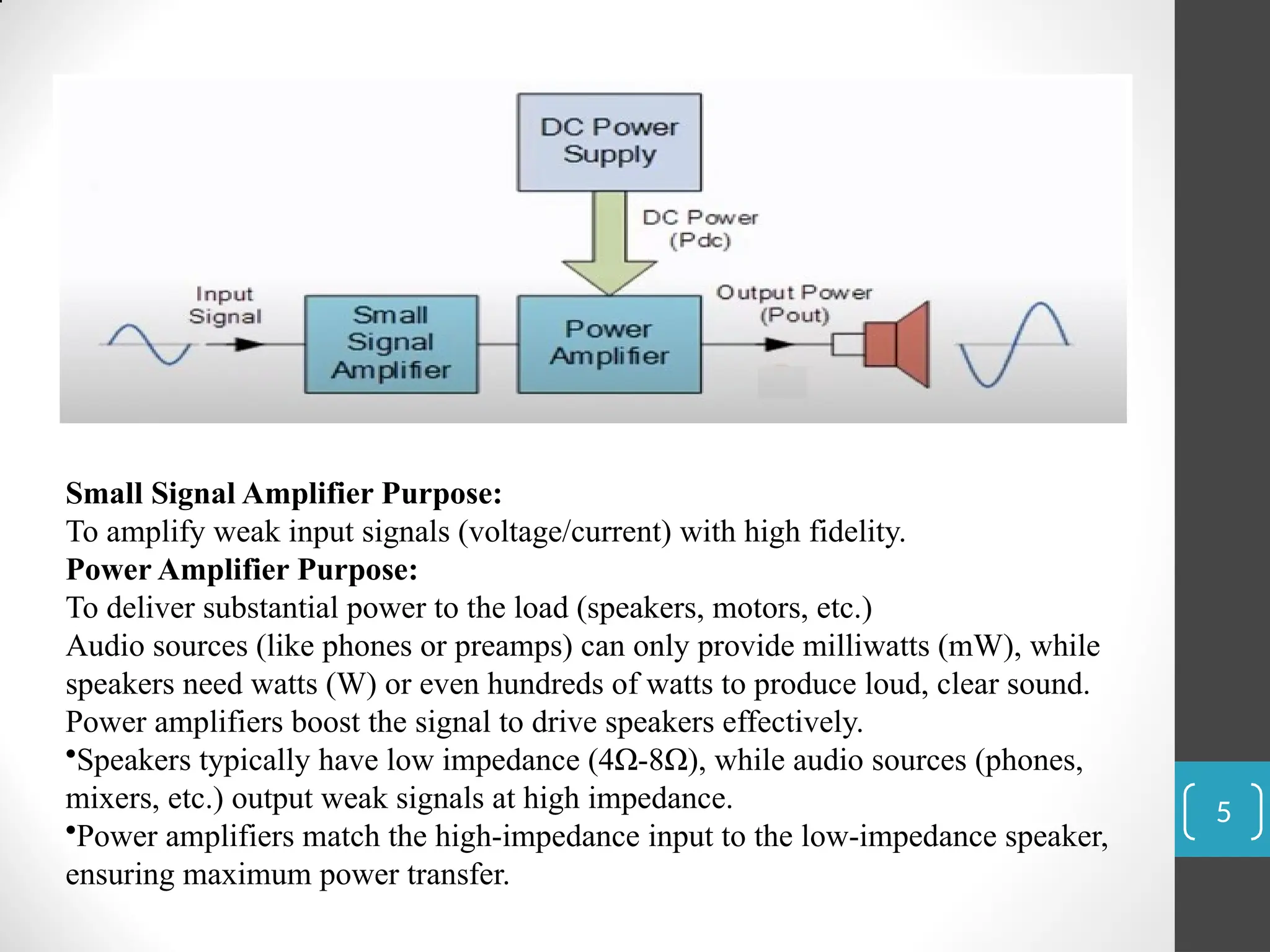
Small Signal AmplifierPurpose:
To amplify weak input signals (voltage/current) with high fidelity.
Power Amplifier Purpose:
To deliver substantial power to the load (speakers, motors, etc.)
Audio sources (like phones or preamps) can only provide milliwatts (mW), while
speakers need watts (W) or even hundreds of watts to produce loud, clear sound.
Power amplifiers boost the signal to drive speakers effectively.
•Speakers typically have low impedance (4Ω-8Ω), while audio sources (phones,
mixers, etc.) output weak signals at high impedance.
•Power amplifiers match the high-impedance input to the low-impedance speaker,
ensuring maximum power transfer.
5
6.
6
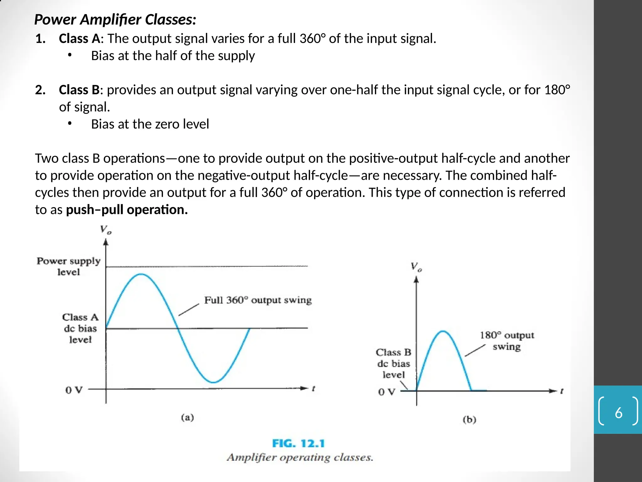
Power Amplifier Classes:
1.Class A: The output signal varies for a full 360° of the input signal.
• Bias at the half of the supply
2. Class B: provides an output signal varying over one-half the input signal cycle, or for 180°
of signal.
• Bias at the zero level
Two class B operations—one to provide output on the positive-output half-cycle and another
to provide operation on the negative-output half-cycle—are necessary. The combined half-
cycles then provide an output for a full 360° of operation. This type of connection is referred
to as push–pull operation.
7.
Amplifier Classes
7
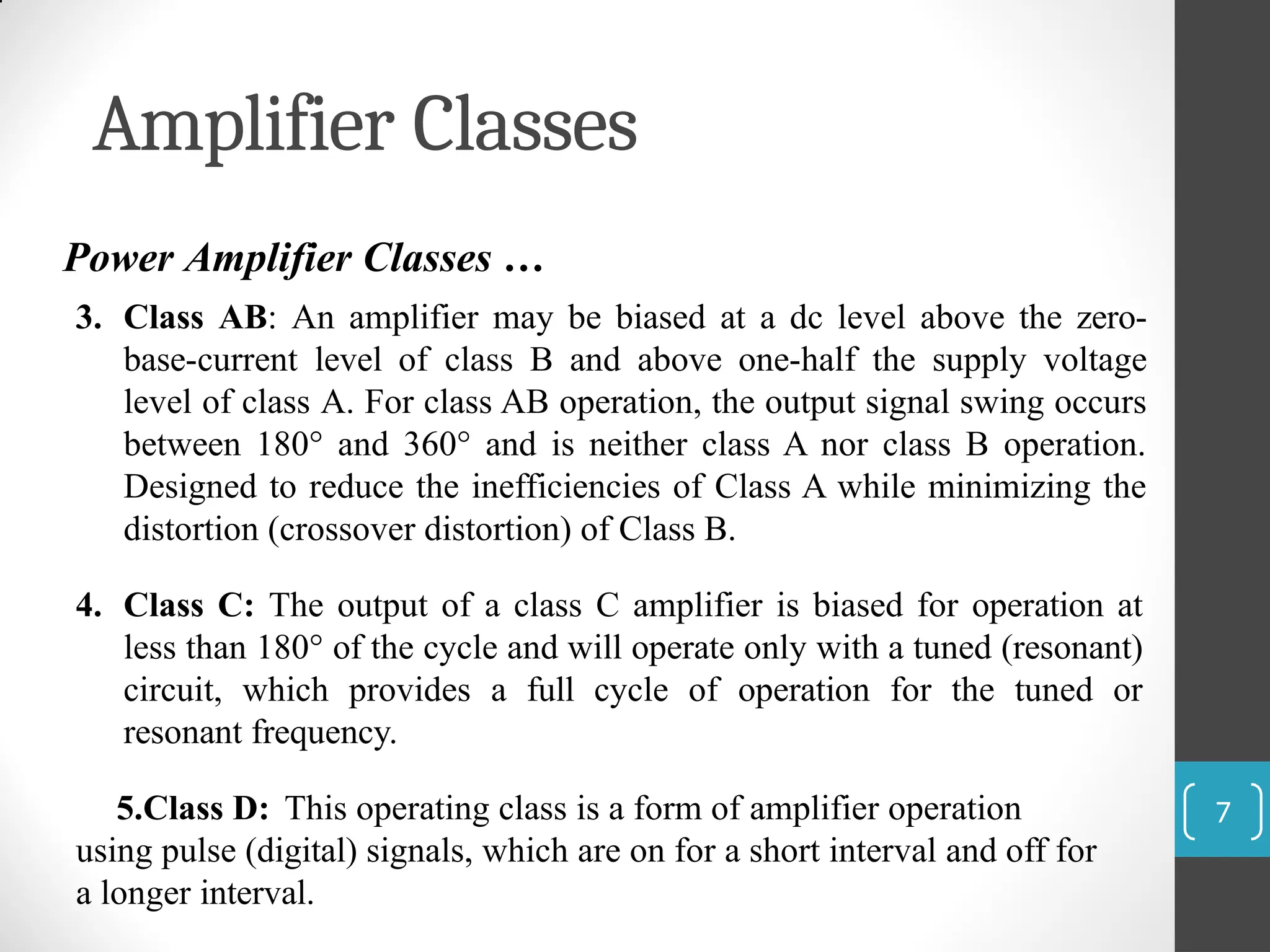
Power AmplifierClasses …
3. Class AB: An amplifier may be biased at a dc level above the zero-
base-current level of class B and above one-half the supply voltage
level of class A. For class AB operation, the output signal swing occurs
between 180° and 360° and is neither class A nor class B operation.
Designed to reduce the inefficiencies of Class A while minimizing the
distortion (crossover distortion) of Class B.
4. Class C: The output of a class C amplifier is biased for operation at
less than 180° of the cycle and will operate only with a tuned (resonant)
circuit, which provides a full cycle of operation for the tuned or
resonant frequency.
5.Class D: This operating class is a form of amplifier operation
using pulse (digital) signals, which are on for a short interval and off for
a longer interval.
8.
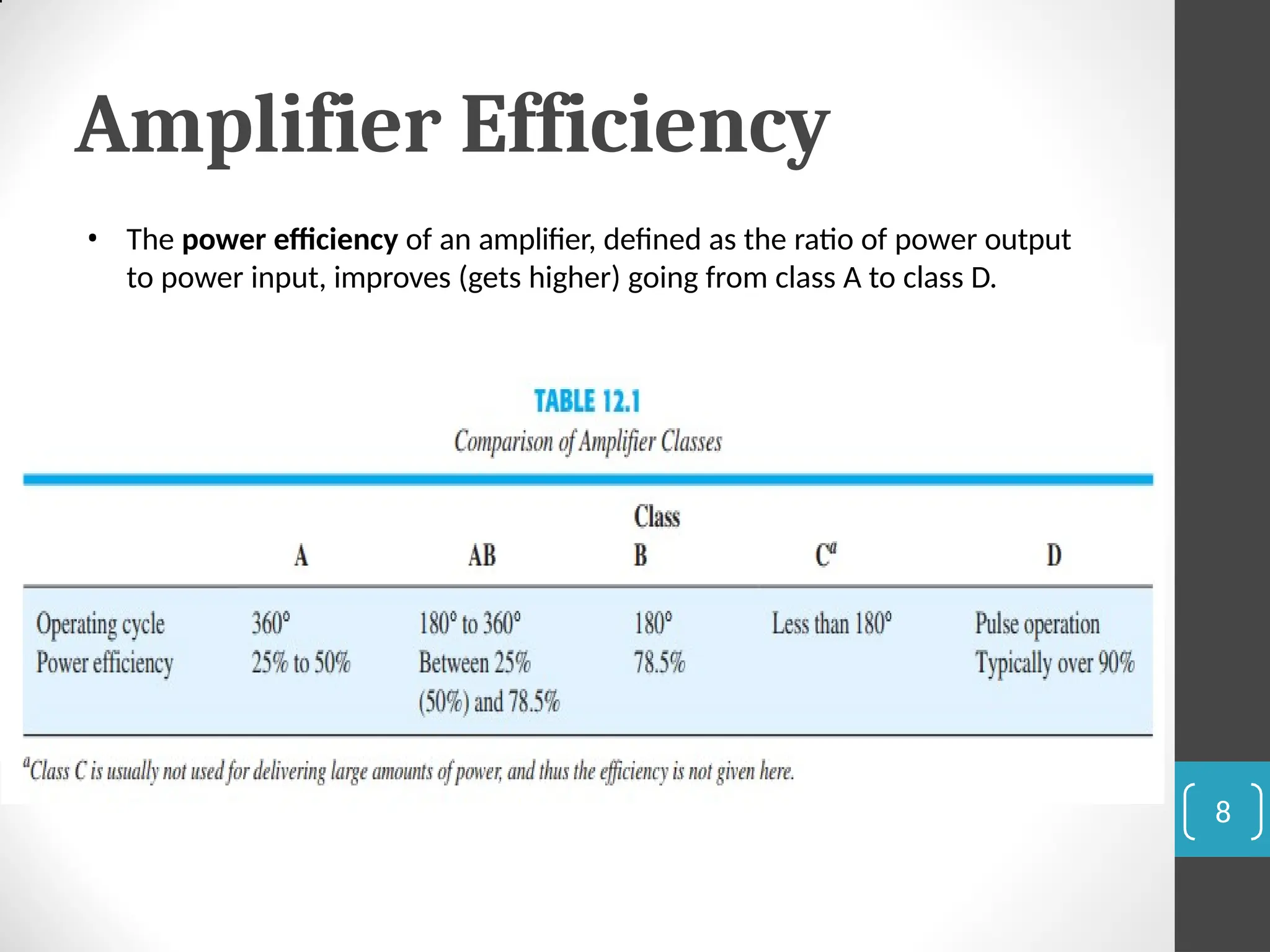
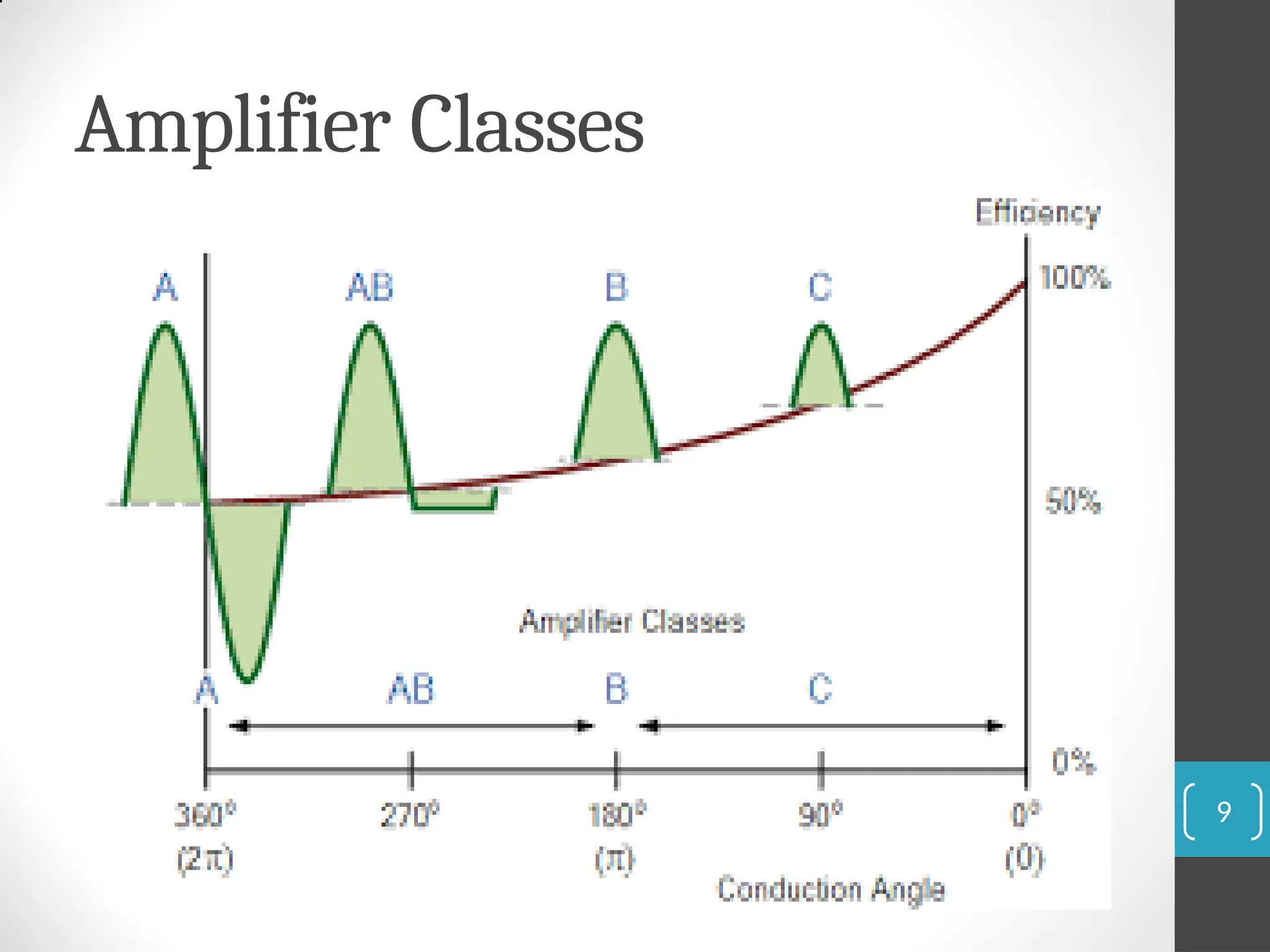
Amplifier Efficiency
• Thepower efficiency of an amplifier, defined as the ratio of power output
to power input, improves (gets higher) going from class A to class D.
8
CLASS A AMPLIFIER
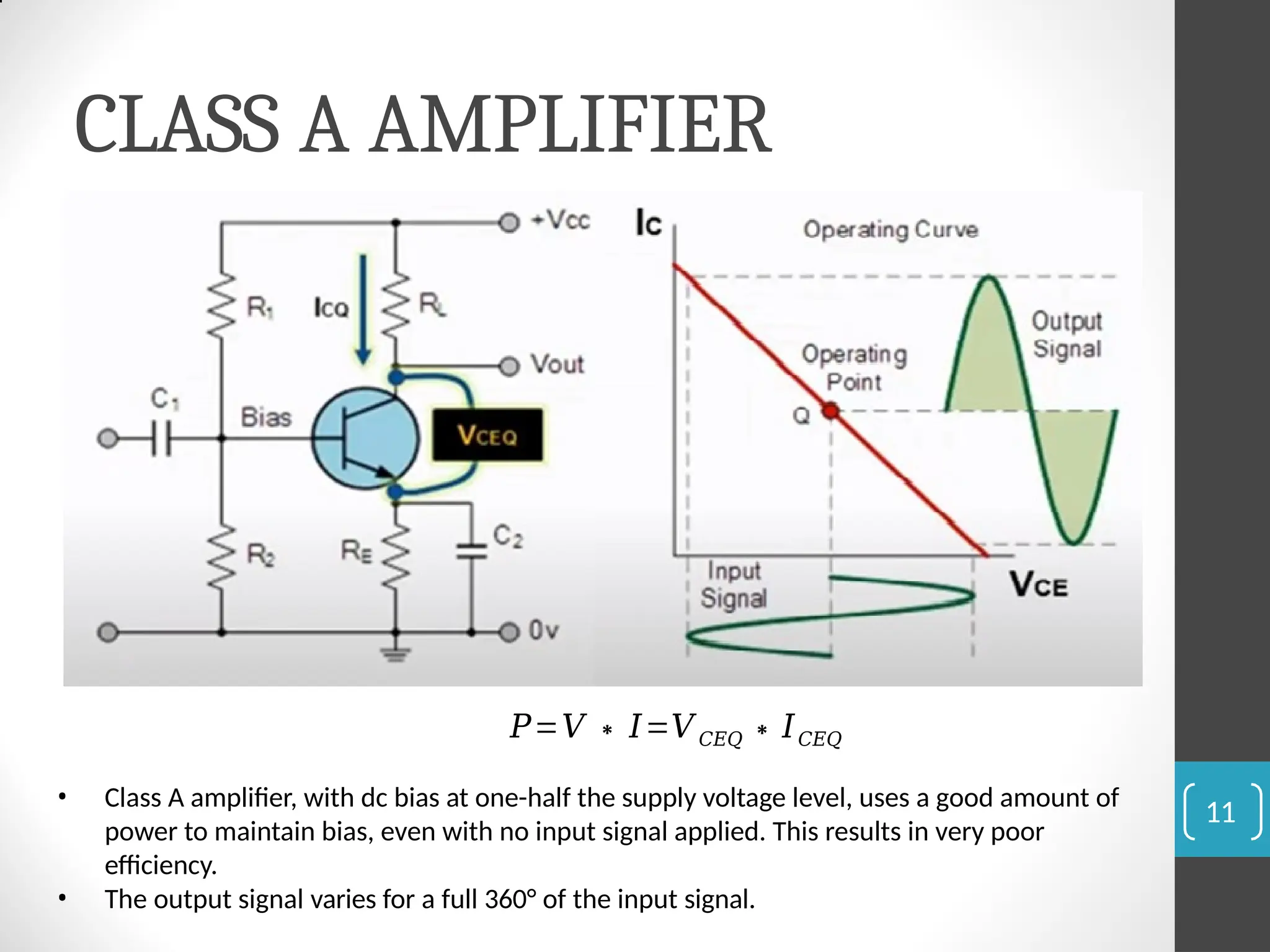
𝑃=𝑉∗ 𝐼=𝑉𝐶𝐸𝑄 ∗𝐼𝐶𝐸𝑄
• Class A amplifier, with dc bias at one-half the supply voltage level, uses a good amount of
power to maintain bias, even with no input signal applied. This results in very poor
efficiency.
• The output signal varies for a full 360° of the input signal.
11
12.
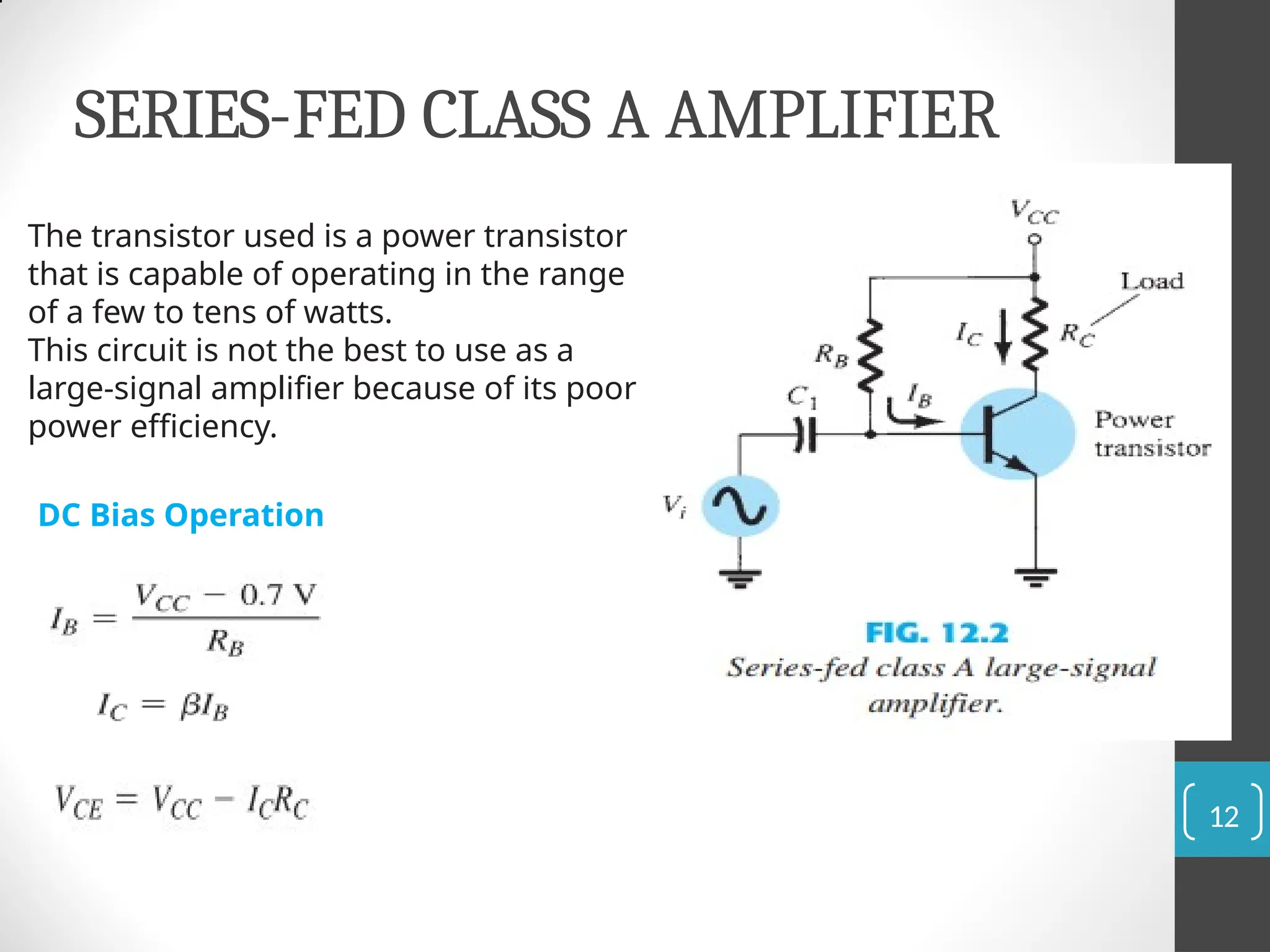
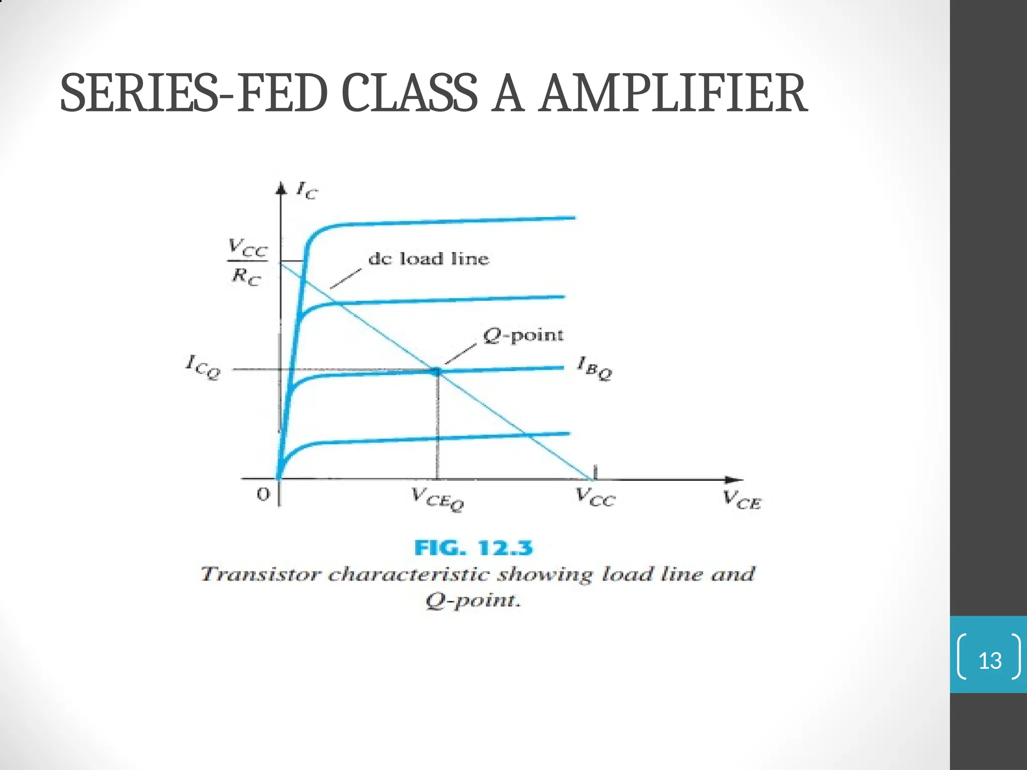
SERIES-FED CLASS AAMPLIFIER
The transistor used is a power transistor
that is capable of operating in the range
of a few to tens of watts.
This circuit is not the best to use as a
large-signal amplifier because of its poor
power efficiency.
DC Bias Operation
12
18
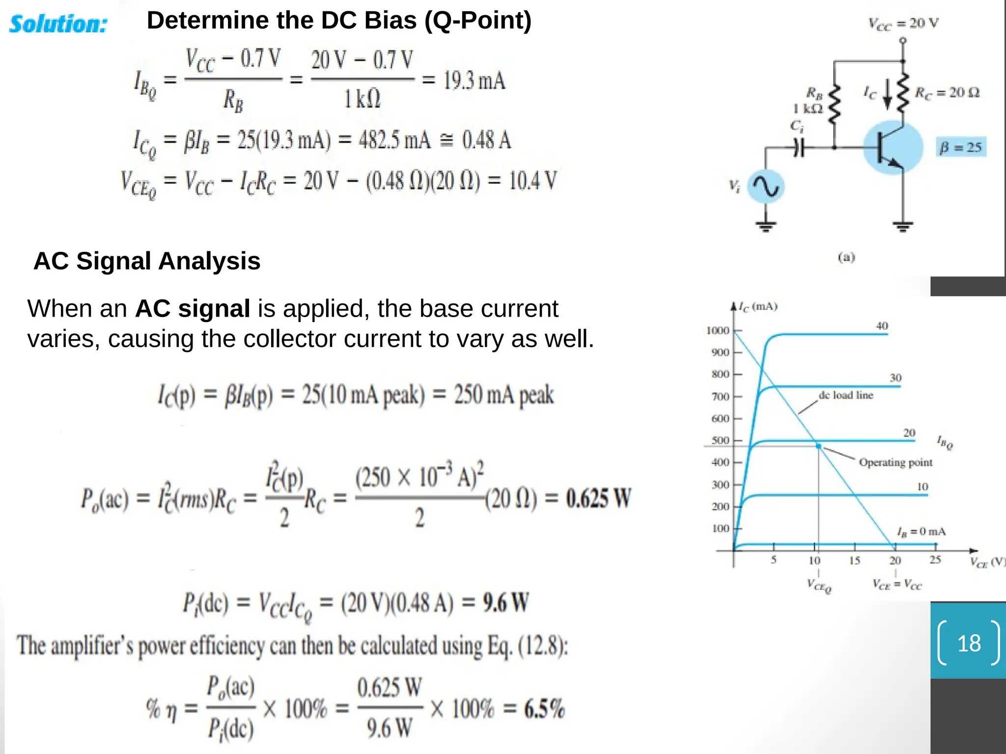
Determine the DCBias (Q-Point)
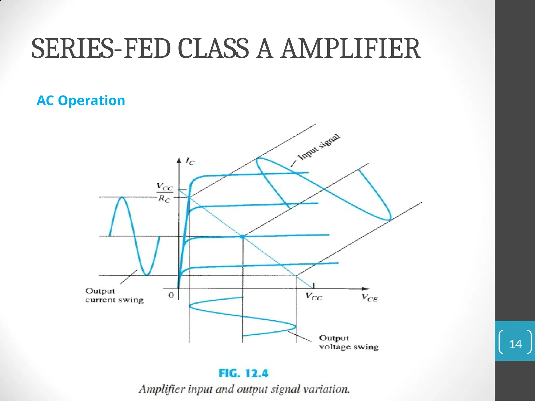
AC Signal Analysis
When an AC signal is applied, the base current
varies, causing the collector current to vary as well.
Transformer Action
20
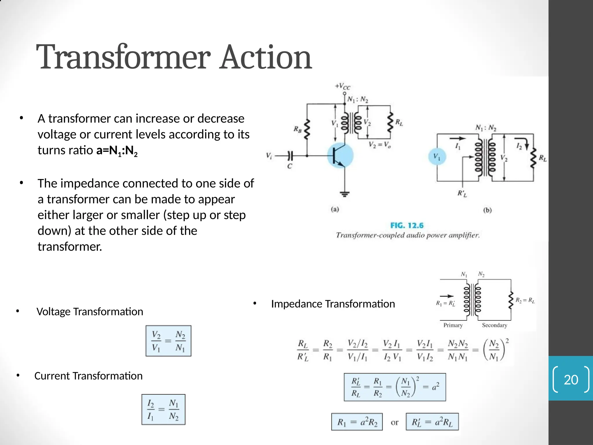
• Atransformer can increase or decrease
voltage or current levels according to its
turns ratio a=N1:N2
• The impedance connected to one side of
a transformer can be made to appear
either larger or smaller (step up or step
down) at the other side of the
transformer.
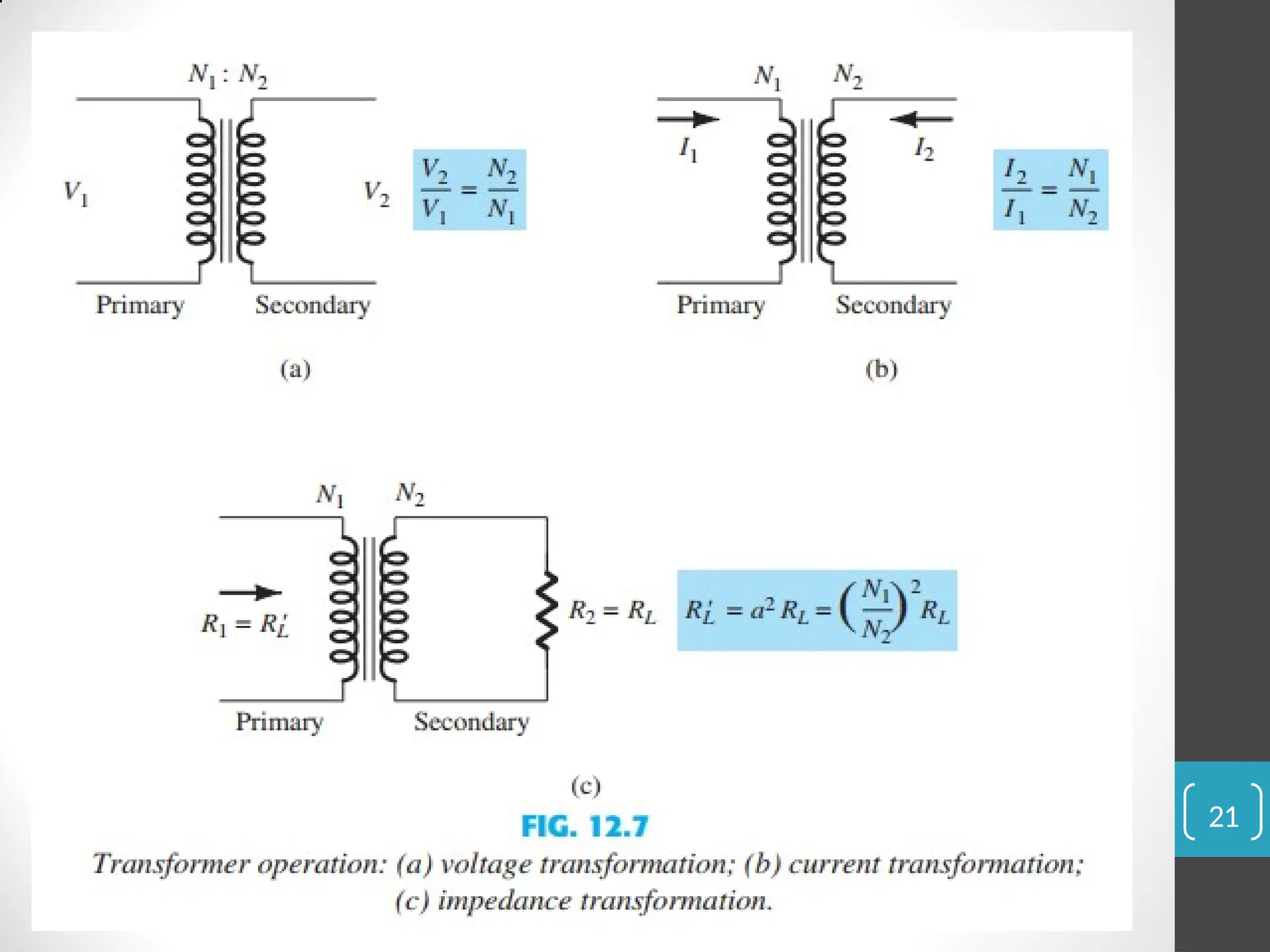
• Voltage Transformation
• Current Transformation
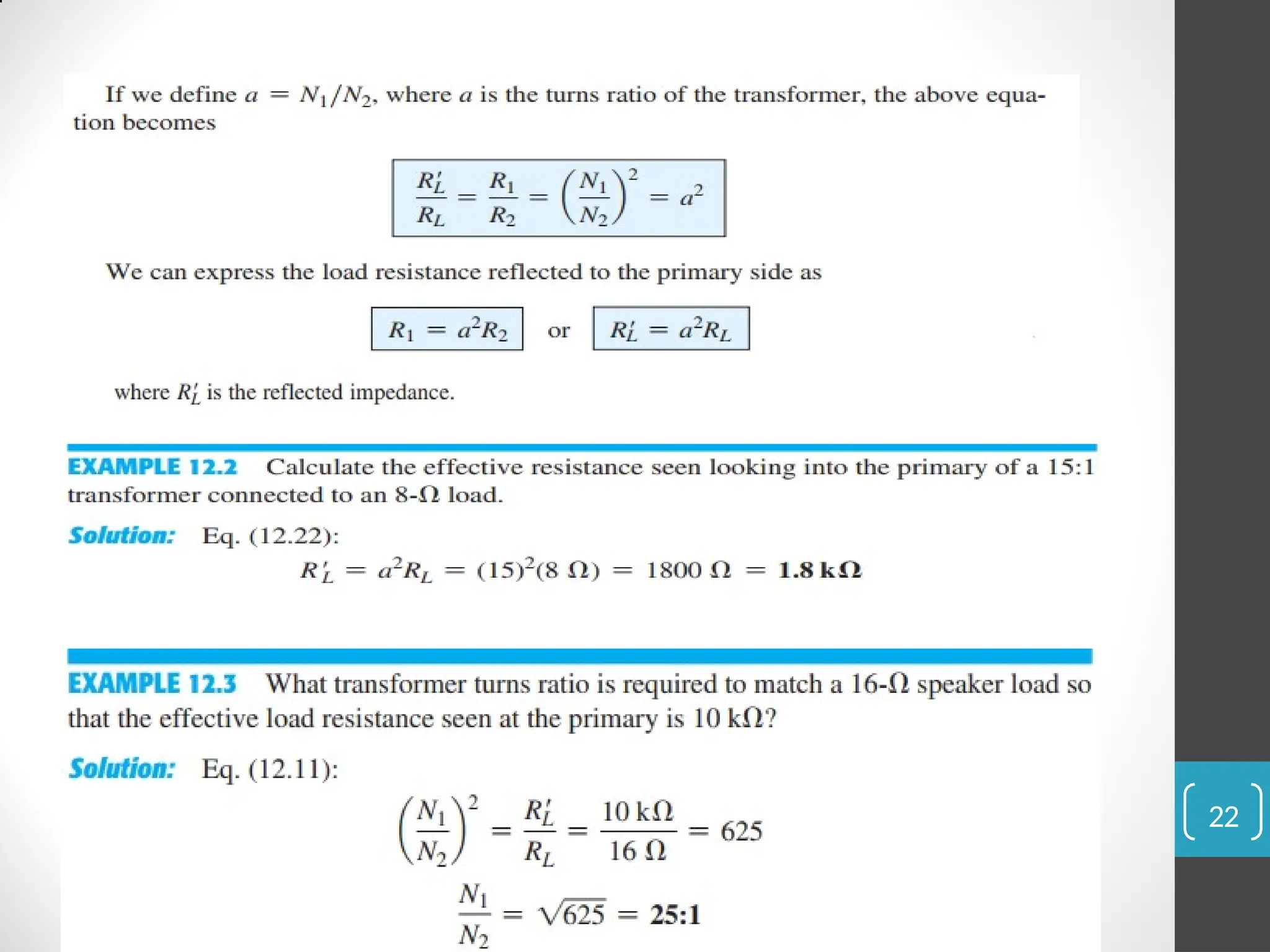
• Impedance Transformation
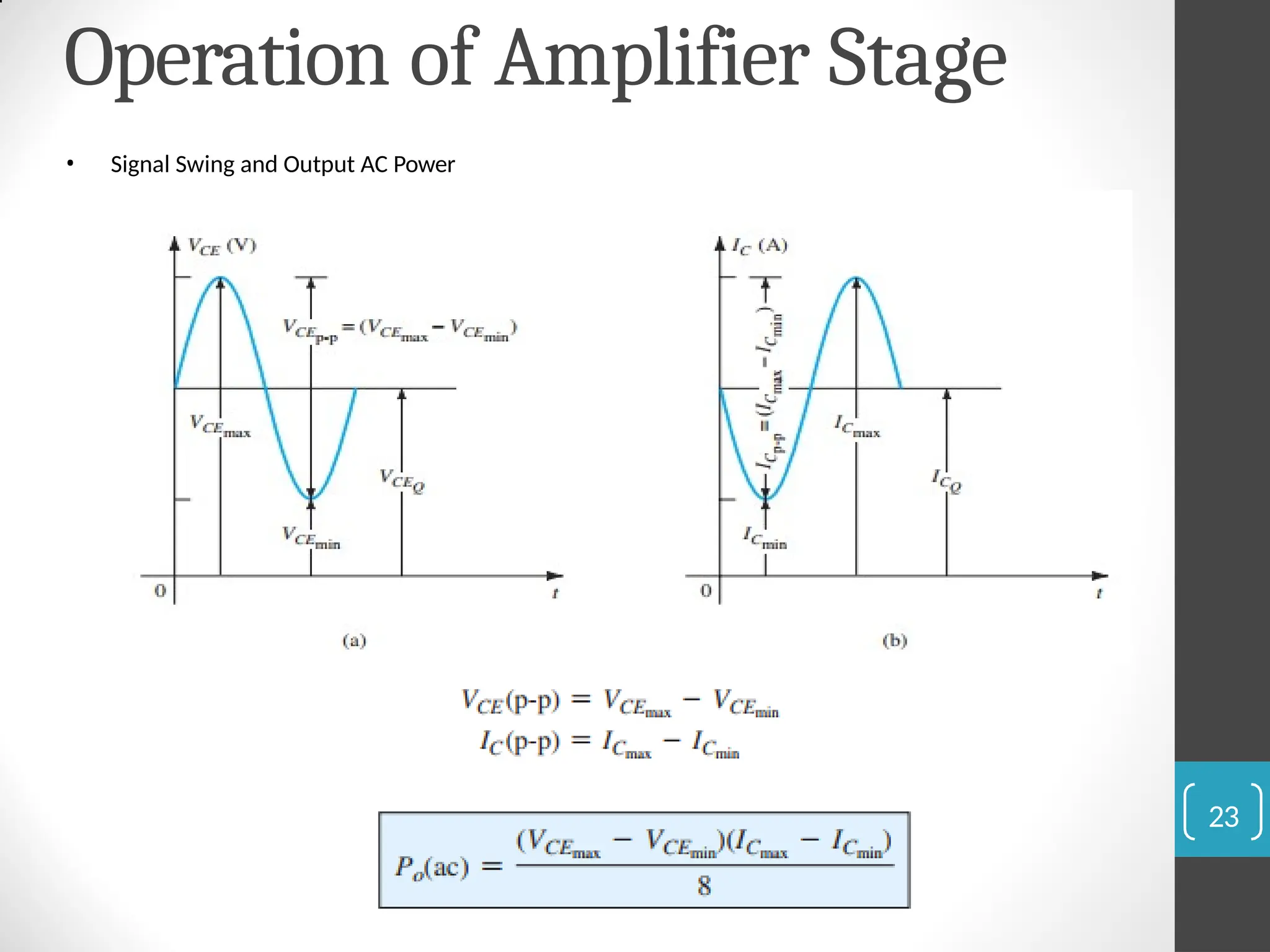
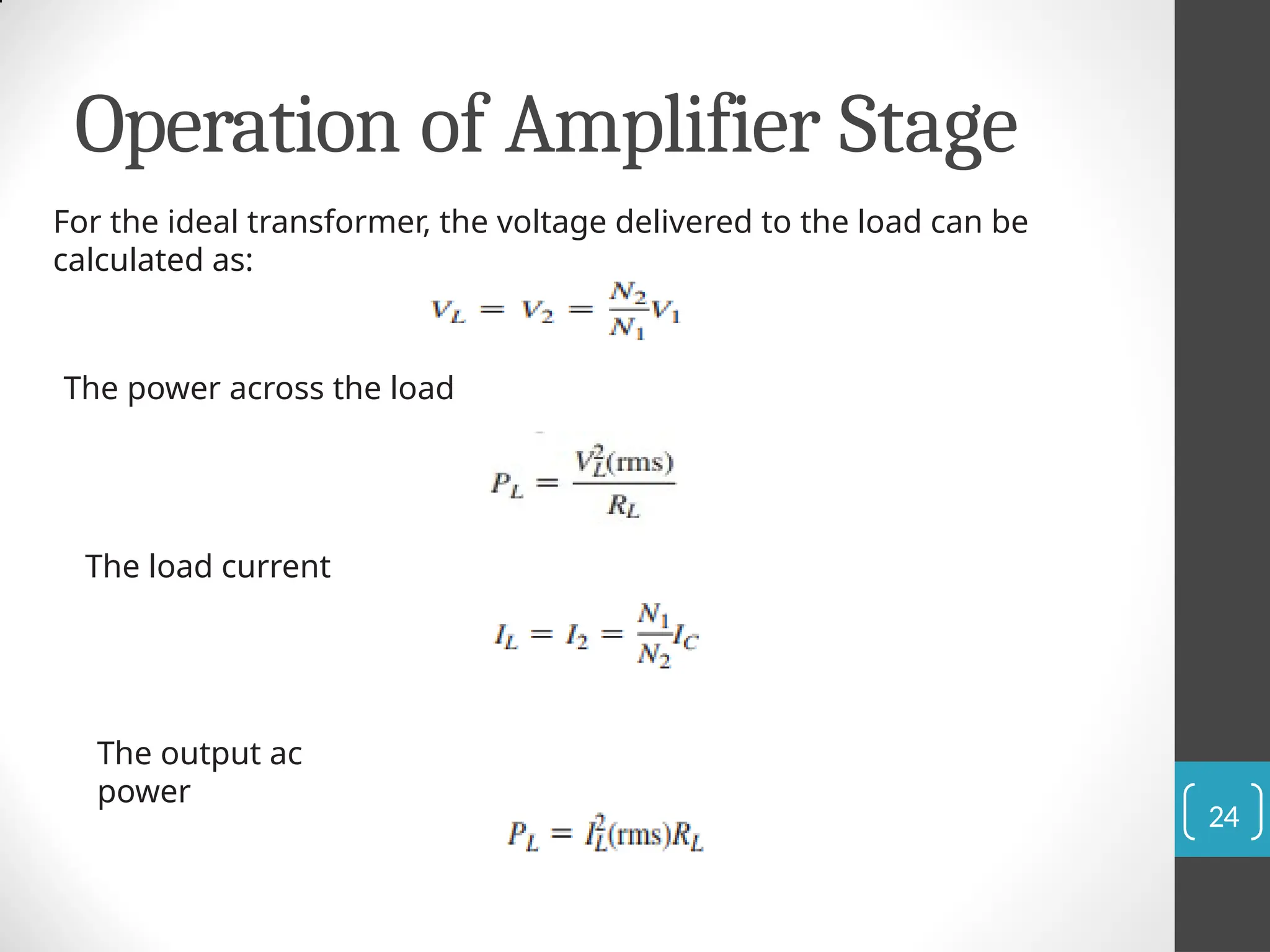
Operation of AmplifierStage
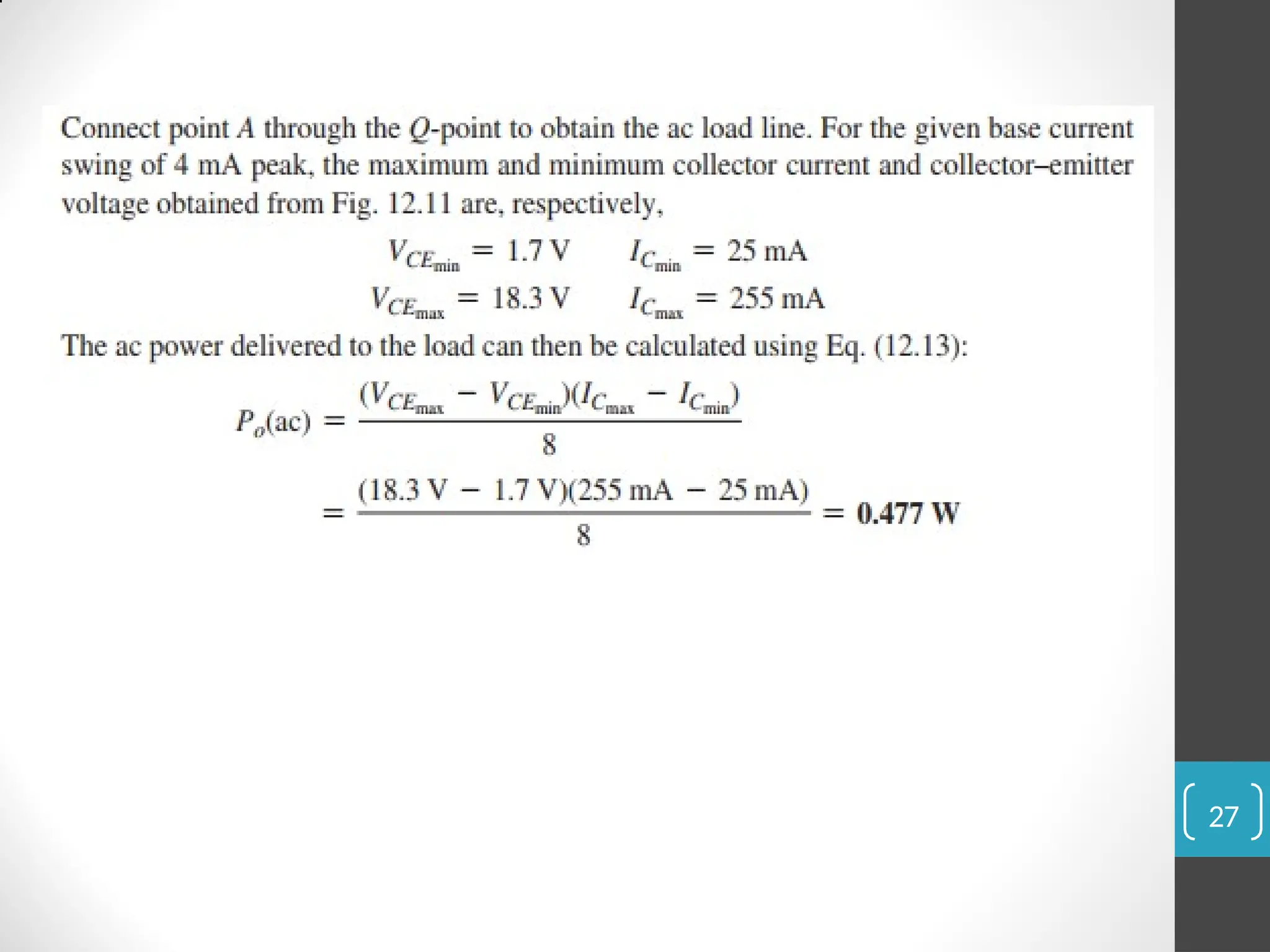
For the ideal transformer, the voltage delivered to the load can be
calculated as:
The power across the load
The load current
The output ac
power
24
Operation of AmplifierStage
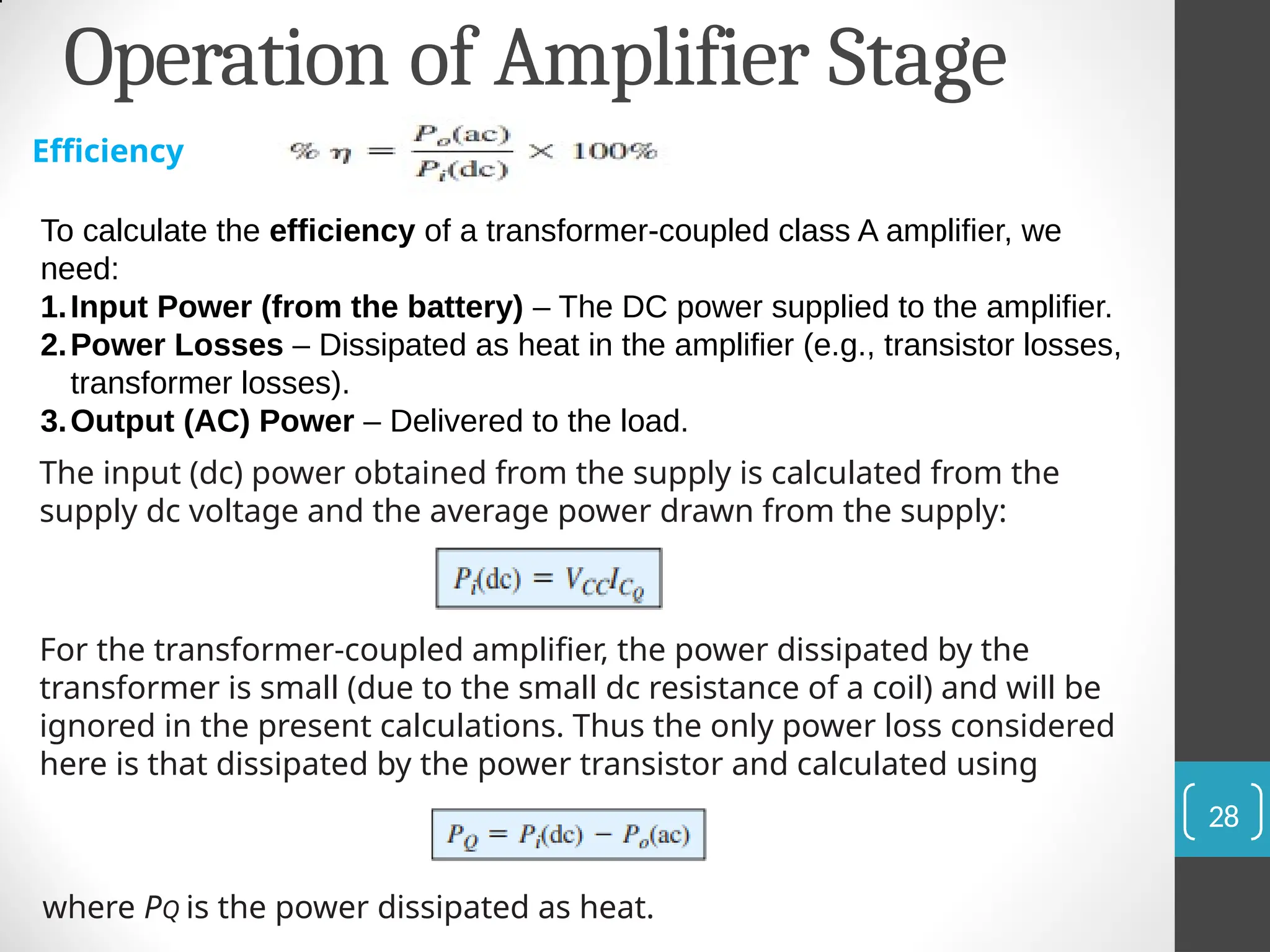
Efficiency
To calculate the efficiency of a transformer-coupled class A amplifier, we
need:
1.Input Power (from the battery) – The DC power supplied to the amplifier.
2.Power Losses – Dissipated as heat in the amplifier (e.g., transistor losses,
transformer losses).
3.Output (AC) Power – Delivered to the load.
The input (dc) power obtained from the supply is calculated from the
supply dc voltage and the average power drawn from the supply:
For the transformer-coupled amplifier, the power dissipated by the
transformer is small (due to the small dc resistance of a coil) and will be
ignored in the present calculations. Thus the only power loss considered
here is that dissipated by the power transistor and calculated using
where PQ is the power dissipated as heat.
28
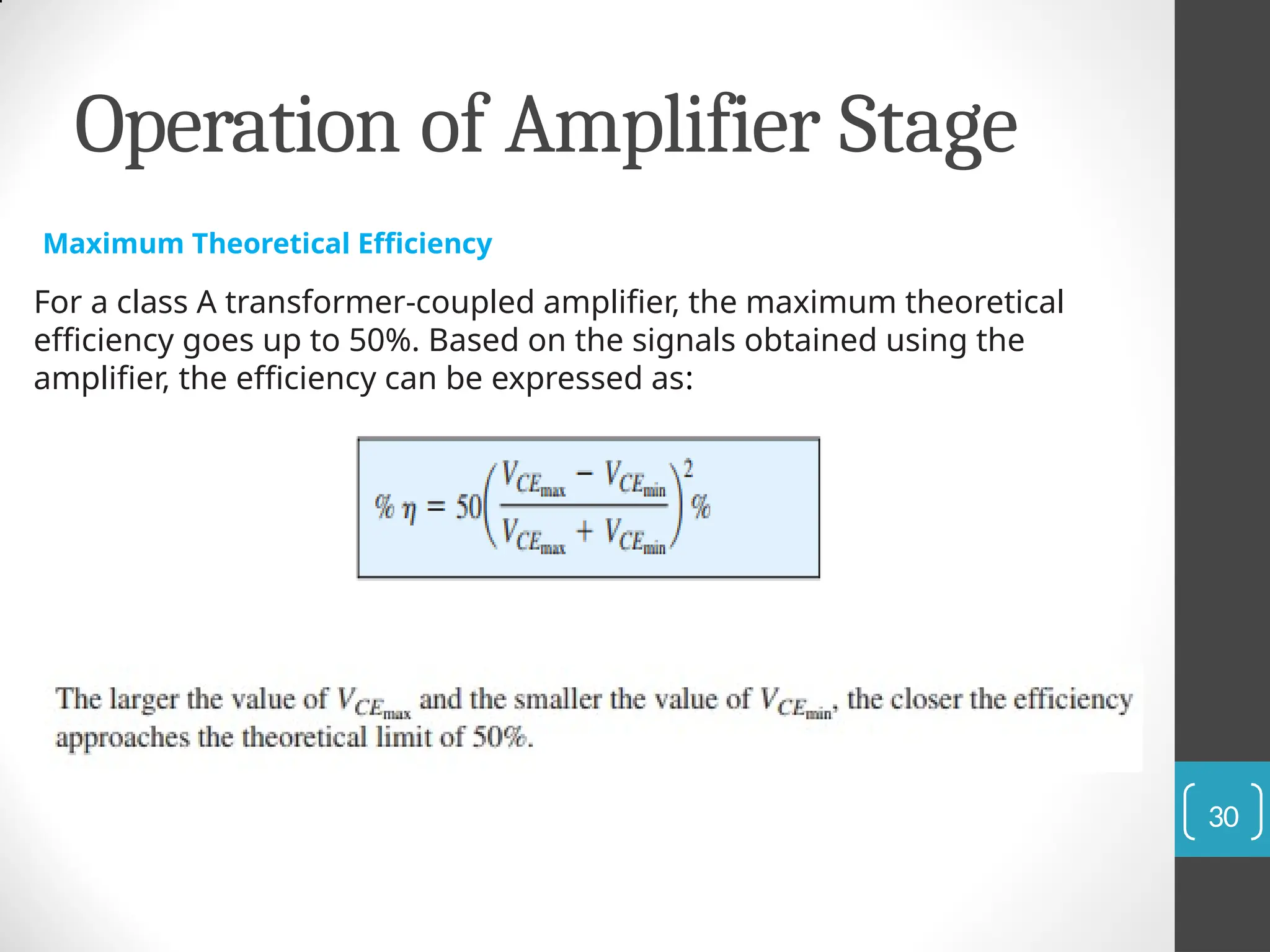
Operation of AmplifierStage
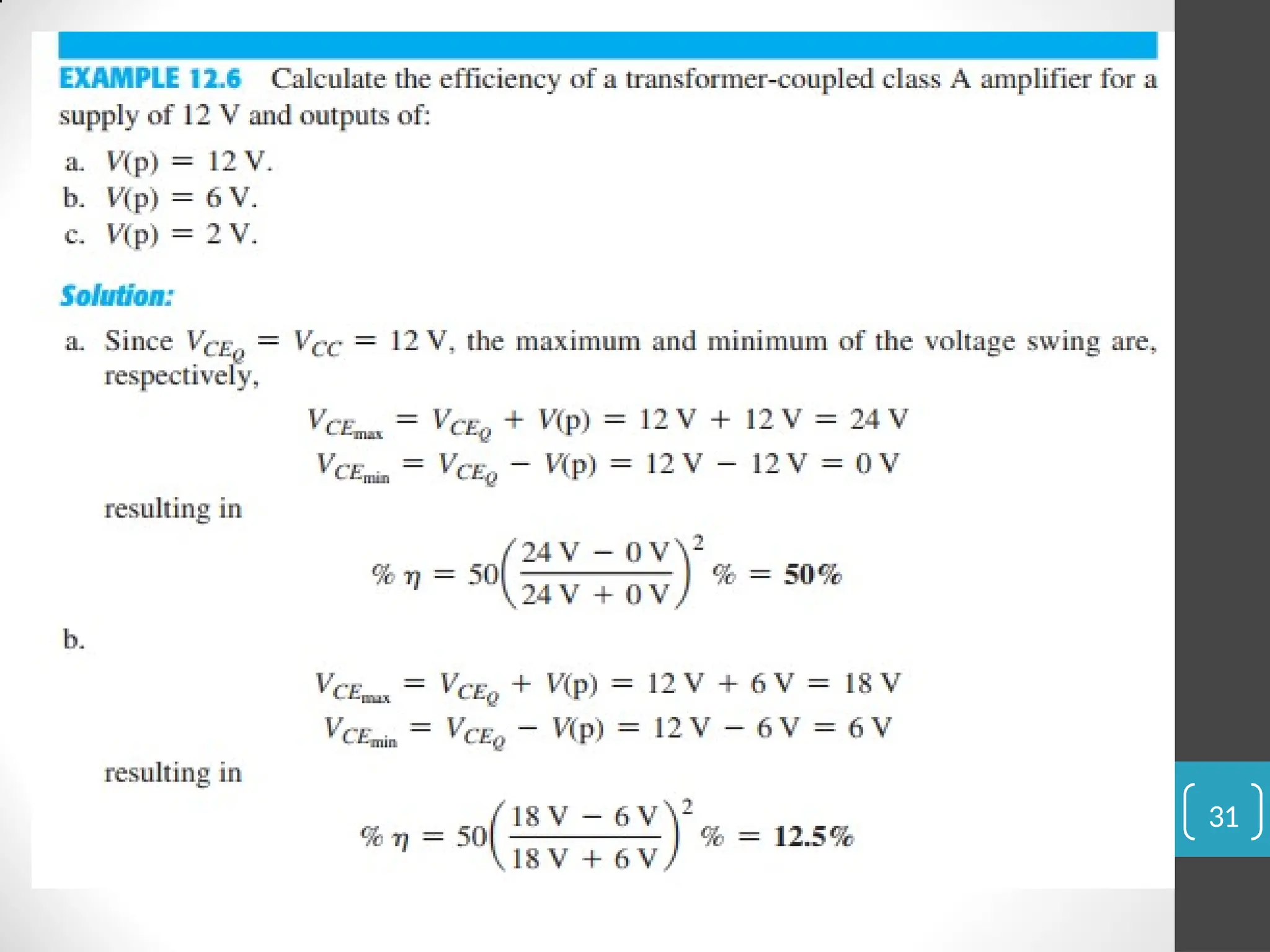
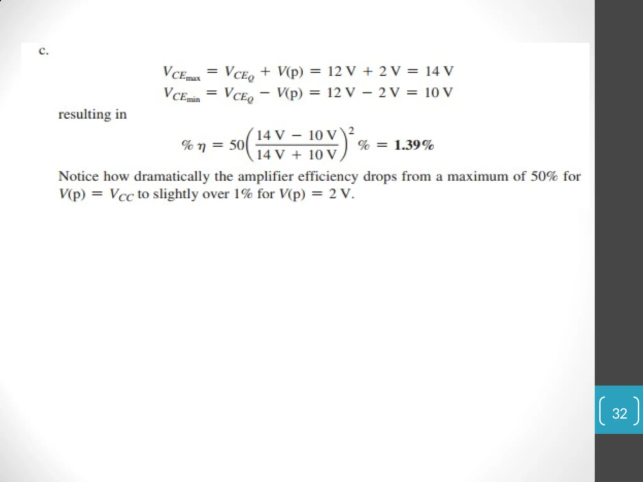
Maximum Theoretical Efficiency
For a class A transformer-coupled amplifier, the maximum theoretical
efficiency goes up to 50%. Based on the signals obtained using the
amplifier, the efficiency can be expressed as:
30