Enhancing the BER and ACLR for the HPA Using Pre-Distortion TechniqueIJECEIAES
Power amplifiers are key components in wireless transceivers. Their function is to amplify signal and generate the required Radio Frequency (RF) power that allows to transmit the signal over an appropriate range. The Orthogonal Frequency Division Multiplexing (OFDM) systems are highly sensitive to nonlinear distortion introduced by High Power Amplifier (HPA). The HPA nonlinearity causes in-band and out-of-band distortions. The linearization techniques are used to compensate the nonlinear effects of the high power amplifier. These techniques correct the distortion effects resulting from nonlinearities in the transmitted signal. Many linearization techniques have been developed to improve power amplifier linearity and to decrease both Bit Error Rate (BER) and Adjacent Channel Leakage Ratio (ACLR). This work is set to run the high power amplifier in the nonlinear region. It is also attempting to analyze the resulting signal in terms of the BER and ACLR, next employs pre-distortion linearization techniques to reduce the distortion introduced in this region. According to Digital Video Broadcasting-Terrestrial (DVB-T) standard the linearization techniques, circuit and the OFDM transmitter and receiver is designed and implemented through using computer simulation of AWR Design Environment.
0.5GHz - 1.5GHz Bandwidth 10W GaN HEMT RF Power Amplifier Design IJECEIAES
With the current development in wireless communication technology, the need for a wide bandwith in RF power amplifier (RF PA) is an essential. In this paper, the design and simulation of 10W GaN HEMT wideband RF PA will be presented. The Source-Pull and Load-Pull technique was used to design the input and output matching network of the RF PA. From the simulation, the RF PA achieved a flat gain between 15dB to 17dB from 0.5GHz to 1.5GHz. At 1.5GHz, the drain efficiency is simulated to achieve 36% at the output power of 40 dBm while the power added efficiency (PAE) was found to be 28.2%.
A Novel Configuration of A Microstrip Power Amplifier based on GaAs-FET for I...IJECEIAES
Power Amplifiers (PA) are very indispensable components in the design of numerous types of communication transmitters employed in microwave technology. The methodology is exemplified through the design of a 2.45GHz microwave power Amplifier (PA) for the industrial, scientific and medical (ISM) applications using microstrip technology. The main design target is to get a maximum power gain while simultaneously achieving a maximum output power through presenting the optimum impedance which is characteristically carried out per adding a matching circuit between the source and the input of the power amplifier and between the load and the output of the power amplifier. A "T" matching technique is used at the input and the output sides of transistor for assure in band desired that this circuit without reflections and to obtain a maximum power gain. The proposed power amplifier for microwave ISM applications is designed, simulated and optimized by employing Advanced Design System (ADS) software by Agilent. The PA shows good performances in terms of return loss, output power, power gain and stability; the circuit has an input return loss of -38dB and an output return loss of -33.5dB. The 1-dB compression point is 8.69dBm and power gain of the PA is 19.4dBm. The Rollet's Stability measure B1 and the stability factor K of the amplifier is greater than 0 and 1 respectively, which shows that the circuit is unconditionally stable. The total chip size of the PA is 73.5× 36 mm 2 .
Design of Wide-band Power Amplifier Based on Power Combiner Technique with Lo...IJECEIAES
RF power amplifiers are one of challenging blocks in designing radio frequency transceivers, this is due to non-linearity behavior of power amplifiers that leads to inter-modulation distortion. This paper presents the design of wide-band power amplifier which combined with parallel coupled line band pass filter at the input and output of power amplifier to allow the only required frequency band to pass through the power amplifier. Class-A topology and ATF-511P8 transistor are used in this design. Advanced Design System software used as a simulation tool to simulate the designed wideband power amplifier. The simulation results showed an input return loss (S11) which less than -10dB, and gain (S21) is higher than 10 dB over the entire frequency band and considers as flat as well. The designed amplifier is stable over the bandwidth (K>1). Inter-modulation distortion is -56.919dBc which is less than -50dBc with 10dBm input power. The designed amplifier can be used for the microwave applications which include weather radar, satellite communication, wireless networking, mobile, and TV.
Negative resistance amplifier circuit using GaAsFET modelled single MESFETTELKOMNIKA JOURNAL
Negative resistance devices have attracted much attention in the wireless communication industry because of their low cost, better performance, high speed, and reduced power requirements. Although negative resistance circuits are non-linear circuits, they are associated with distortion, which may either be amplitude-to-amplitude distortion or amplitude-to-phase distortion. In this paper, a unique way of realizing a negative resistance amplifier is proposed using a single metal-semiconductor field-effect transistor (MESFET). Intermodulation distortion test (IMD) is performed to evaluate the characteristic response of the negative resistance circuit amplifier to different bias voltages using the harmonic balance (HB) of the advanced designed software (ADS 2016). The results obtained are compared to those of a conventional distributed amplifier. The findings of this study showed that the negative resistance amplifier spreads over a wider frequency output with reduced power requirements while the conventional distributed amplifier has a direct current (DC) offset with output voltage of 32.34 dBm.
International Journal of Engineering Research and Applications (IJERA) is an open access online peer reviewed international journal that publishes research and review articles in the fields of Computer Science, Neural Networks, Electrical Engineering, Software Engineering, Information Technology, Mechanical Engineering, Chemical Engineering, Plastic Engineering, Food Technology, Textile Engineering, Nano Technology & science, Power Electronics, Electronics & Communication Engineering, Computational mathematics, Image processing, Civil Engineering, Structural Engineering, Environmental Engineering, VLSI Testing & Low Power VLSI Design etc.
A Novel Design of Voltage Controlled Oscillator by Using the Method of Negati...IJECEIAES
The objective of this paper is to develop a new design of a voltage controlled microwave oscillator by using the method of negative resistance in order to fabricate VCO with very good performance in terms of tuning rang, phase noise, output power and stability. The use of hybrid microwave integrated circuit technology’s (HMIC) offers a lot of advantage for our structure concerning size, cost, productivity, and Q factor. This VCO is designed at [480MHz; 1.4GHz] frequency for applications in the phase locked loop (PLL) for signal tracking, FM demodulation, frequency modulation, mobile communication, etc. The different steps of studied voltage controlled oscillator’s design are thoroughly described. Initially designed at a fixed frequency meanwhile the use of a varactor allow us to tune the frequency of the second design. It has been optimized especially regarding tuning bandwidth, power, phase noise, consumption and size of the whole circuit. The achieved results and proposed amendment are the product of theoretical study and predictive simulations with advanced design system microwave design software. A micro-strip VCO with low phase noise based on high gain ultra low noise RF transistor BFP 740 has been designed, fabricated, and characterized. The VCO delivers a sinusoidal signal at the frequency 480 MHz with tuning bandwidth 920 MHz, spectrum power of 12.62 dBm into 50 Ω load and phase noise of -108 dBc/Hz at 100 Hz offset. Measurement results and simulation are in good agreement. Circuit is designed on FR4 substrate which includes integrated resonators and passive components.
This paper relates the new topology and simulations of a fully differential CMOS active filter for mm wave band applications. The advantages of the differential topology over the single ended one are discussed and the quality factor is tuned to insure application requirements, including narrow bandwidth and high selectivity due to a differential negative resistance that reuses the filter’s current. Using this topology enables independent tuning of the quality factor and low power consumption while compensating the resistive loss of the filter. Very high filter performance was obtained with the simulated active inductor based active filter that was designed using CMOS 0.35 µm technology from AMS foundry and that resonates at 30 GHz with a high quality factor of Q > 500.
Interleaved digital power factor correction based on the sliding mode approachLeMeniz Infotech
Interleaved Digital Power Factor Correction Based on the Sliding-Mode Approach
This study describes a digitally controlled power factor correction (PFC) system based on two interleaved boost converters operating with pulsewidth modulation (PWM). Both converters are independently controlled by an inner control loop based on a discrete-time sliding-mode (SM) approach that imposes loss-free resistor (LFR) behavior on each cell. The switching surface implements an average current-mode controller so that the power factor (PF) is high. The SM-based digital controller is designed to operate at a constant switching frequency so that the interleaving technique, which is recommended for ac-dc power conversion systems higher than 1 kW, can be readily applied. An outer loop regulates the output voltage by means of a discrete-time proportional-integral (PI) compensator directly obtained from a discrete-time small-signal model of the ideal sliding dynamics. The control law proposed has been validated using numerical simulations and experimental results in a 2-kW prototype.
Web : http://www.lemenizinfotech.com
web : http://www.lemenizinfotech.com/tag/ieee-projects-in-pondicherry/
Web : http://ieeemaster.com
Web : http://ieeemaster.com/power-electronics-ieee-projects-2016-2017/
Web : http://ieeemaster.com/power-system-ieee-projects-2016-2017/
Address: 36, 100 Feet Road(Near Indira Gandhi Statue), Natesan Nagar, Pondicherry-605 005
Contact numbers: +91 95663 55386, 99625 88976 (0413) 420 5444
Mail : projects@lemenizinfotech.com
Mobile : 9566355386 / 9962588976
Wideband power amplifier based on Wilkinson power divider for s-band satellit...journalBEEI
This paper presents design and simulation of wideband power amplifier based on multi-section Wilkinson power divider. Class-A topology and ATF-511P8 transistor have been used. Advanced Design System (ADS) software used to simulate the designed power amplifier. The simulation results show an input return loss (S11)<-10dB, gain (S21)>10 dB over the entire bandwidth, and an output power around 28dBm at the Centre frequency of 3GHz. The designed amplifier is stable over the entire bandwidth (K>1). Inter-modulation distortion is -65.187dBc which is less than -50dBc. The designed amplifier can be used for the microwave applications which include weather radar, satellite communication, wireless networking, mobile, and TV.
A low dropout (LDO) voltage regulator with high power supply rejection ratio (PSRR) and low
temperature coefficient (TC) is presented in this paper. Large 1μF off-chip load capacitor is used to
achieve the high PSRR. However, this decreases the gain and pushes the LDO’s output pole to lower
frequency causing the circuit to become unstable. The proposed LDO uses rail-to-rail folded cascode
amplifier to compensate the gain and stability problems. 2nd order curvature characteristic is used in
bandgap voltage reference circuit that is applied at the input of the amplifier to minimize the TC.
The characteristic is achieved by implementing MOSFET transistors operate in weak and strong
inversions. The LDO is designed using 0.18 μm CMOS technology and achieves a constant 1.8 V output
voltage for input voltages from 3.2 V to 5 V and load current up to a 128mA at temperature between -40 °C
to 125 °C. The proposed LDO is targeted for RF application which has stringent requirement on noise
rejection over a broad range of frequency.
LOW POWER SI CLASS E POWER AMPLIFIER AND RF SWITCH FOR HEALTH CAREieijjournal
This research was to design a 2.4 GHz class E Power Amplifier (PA) for health care, with 0.18um
Semiconductor Manufacturing International Corporation CMOS technology by using Cadence software.
And also RF switch was designed at cadence software with power Jazz 180nm SOI process. The ultimate
goal for such application is to reach high performance and low cost, and between high performance and
low power consumption design. This paper introduces the design of a 2.4GHz class E power amplifier and RF switch design. PA consists of cascade stage with negative capacitance. This power amplifier can transmit 16dBm output power to a 50Ω load. The performance of the power amplifier and switch meet the specification requirements of the desired.
The design & simulation of low noise amplifier for 1 2.8 ghz using aln s...eSAT Journals
Abstract In this paper, we have designed low noise amplifier using 2 stage Cascade topology. We have focused on intermediate matching network design of amplifier for low noise figure and selection of transistor PHEMT is based on noise figure as well as quiescent point required for 0 grid voltage so that amplifier will need only single DC supply i.e. Vdd. Depends upon different topologies used for LNA design with wide band requirement, we chose cascaded topology for good gain with low noise amplifier and optimized for greater bandwidth. Practical inductors are bulky as well as counter intuitive elements for high frequency as they behave as capacitors and to reduce S11. Several windings in inductors make them resistive which increases noise by 0.2-0.4 dB. So we proposed inductor-less input matching network for both stages so that we can increase bandwidth as well as perfect match for low noise figure. This LNA is designed using Advanced Design System (ADS) software to provide 0.5 dB noise figure with power gain of 25 dB and 1-2.5 GHz Bandwidth. So it can be used an L-Band satellite modem that is used in an asset tracking application. Layout is designed using muruta manufacturing lumped components and Aluminum Nitride (AlN) substrate having high dielectric constant and high thermal conductivity. Key Words: LNA, PHEMT, ADS, AlN
Qualitative Analysis of Darlington Feedback Amplifier at 45nm TechnologyjournalBEEI
The transistors are the key element of present communication system having high data rate. Some applications need high gain by using very low frequency, and then transistors are used. Amplifier is the key element in many applications of present high data rate communication system such as low noise amplifier (LNA), broadband amplifier, distributed and power amplifier. The Darlington pair amplifier is analyzed for high frequency performance and related effect of bandwidth. Broadband feedback Darlington pair amplifier is designed with enhanced gain, bandwidth and slew rate. This paper presents the comparison of single stage and three stage feedback Darlington feedback amplifier with reference to gain, bandwidth and slew rate. This paper is simulated on cadence analog design environment at GPDK 45nm technology. This paper shows that increase in gain, bandwidth and slew rate of three stage Darlington feedback amplifier can show better stability over the single stage Darlington feedback amplifier.
International Journal of Engineering Research and Applications (IJERA) is an open access online peer reviewed international journal that publishes research and review articles in the fields of Computer Science, Neural Networks, Electrical Engineering, Software Engineering, Information Technology, Mechanical Engineering, Chemical Engineering, Plastic Engineering, Food Technology, Textile Engineering, Nano Technology & science, Power Electronics, Electronics & Communication Engineering, Computational mathematics, Image processing, Civil Engineering, Structural Engineering, Environmental Engineering, VLSI Testing & Low Power VLSI Design etc.
Design of 10 to 12 GHz Low Noise Amplifier for Ultrawideband (UWB) SystemIJECEIAES
Balanced amplifier is the structure proposed in this article, it provides better performance. In fact, the single amplifier meets the specification for noise figure and gain but fails to meet the return loss specification due to the large mis-matches on the input & outputs. To overcome this problem one solution is to use balanced amplifier topography. In this paper, a wide-band and highgain microwave balanced amplifier constituted with branch line coupler circuit is proposed. The amplifier is unconditionally stable in the band [9-13] GHz where the gain is about 20dB. The input reflection (S11) and output return loss (S22) at 11 GHz are -33.4dB and -33.5dB respectively.
This paper gives a step-by-step of the design, simulation and measurement of a Power Amplifier(PA) operating frequency from 2.5GHz to 4.5GHz. The design of Class A Power amplifier was performed in Agilent ADS and the performance was tested with SZA3044Z BJT
Review on Design and Performance Analysis of Low Power Transceiver Circuit in...iosrjce
IOSR Journal of Electronics and Communication Engineering(IOSR-JECE) is a double blind peer reviewed International Journal that provides rapid publication (within a month) of articles in all areas of electronics and communication engineering and its applications. The journal welcomes publications of high quality papers on theoretical developments and practical applications in electronics and communication engineering. Original research papers, state-of-the-art reviews, and high quality technical notes are invited for publications.
LOW POWER SI CLASS E POWER AMPLIFIER AND RF SWITCH FOR HEALTH CAREieijjournal1
This research was to design a 2.4 GHz class E Power Amplifier (PA) for health care, with 0.18um
Semiconductor Manufacturing International Corporation CMOS technology by using Cadence software.
And also RF switch was designed at cadence software with power Jazz 180nm SOI process. The ultimate
goal for such application is to reach high performance and low cost, and between high performance and
low power consumption design. This paper introduces the design of a 2.4GHz class E power amplifier and
RF switch design. PA consists of cascade stage with negative capacitance. This power amplifier can
transmit 16dBm output power to a 50Ω load. The performance of the power amplifier and switch meet the
specification requirements of the desired.
LOW POWER SI CLASS E POWER AMPLIFIER AND RF SWITCH FOR HEALTH CAREieijjournal
This research was to design a 2.4 GHz class E Power Amplifier (PA) for health care, with 0.18um
Semiconductor Manufacturing International Corporation CMOS technology by using Cadence software.
And also RF switch was designed at cadence software with power Jazz 180nm SOI process. The ultimate goal for such application is to reach high performance and low cost, and between high performance and low power consumption design. This paper introduces the design of a 2.4GHz class E power amplifier and
RF switch design. PA consists of cascade stage with negative capacitance. This power amplifier can
transmit 16dBm output power to a 50Ω load. The performance of the power amplifier and switch meet the specification requirements of the desired.
LOW POWER SI CLASS E POWER AMPLIFIER AND RF SWITCH FOR HEALTH CAREieijjournal
This research was to design a 2.4 GHz class E Power Amplifier (PA) for health care, with 0.18um
Semiconductor Manufacturing International Corporation CMOS technology by using Cadence software.
And also RF switch was designed at cadence software with power Jazz 180nm SOI process. The ultimate
goal for such application is to reach high performance and low cost, and between high performance and
low power consumption design. This paper introduces the design of a 2.4GHz class E power amplifier and
RF switch design. PA consists of cascade stage with negative capacitance. This power amplifier can
transmit 16dBm output power to a 50Ω load. The performance of the power amplifier and switch meet the
specification requirements of the desired
Low Power SI Class E Power Amplifier and Rf Switch for Health Careieijjournal1
This research was to design a 2.4 GHz class E Power Amplifier (PA) for health care, with 0.18um Semiconductor Manufacturing International Corporation CMOS technology by using Cadence software. And also RF switch was designed at cadence software with power Jazz 180nm SOI process. The ultimate goal for such application is to reach high performance and low cost, and between high performance and low power consumption design. This paper introduces the design of a 2.4GHz class E power amplifier and RF switch design. PA consists of cascade stage with negative capacitance. This power amplifier can transmit 16dBm output power to a 50Ω load. The performance of the power amplifier and switch meet the specification requirements of the desired.
Abstract:
This paper reports on the design of an ultra wideband power amplifier using 0.25um GaN- HEMT Technology device obtained from the Triquint Semiconductor. There is huge interest in transistors based on Gallium Nitride in recent years due to its high breakdown voltage and its capability to operate in High frequency applications. The load pull analysis is carried out to obtain both the required source and load impedances. The
power amplifier with over 10W output power and 42% power added efficiency in the frequency range of 3-5GHz is presented in this paper. The PA is designed using a computer aided design tool called Advanced System Design (ADS).ADS provide two different simulation opportunities. These are referred as schematic simulation and
electromagnetic simulation called Momentum. Schematic Simulations are performed on the proposed PA in this paper.
Keywords:- GaN-HEMT Technology, Load pull analysis, Advanced system design(ADS)
A 10 d bm 25 dbm, 0.363 mm2 two stage 130 nm rf cmos power amplifierVLSICS Design
This paper proposes a 2.4 GHz RF CMOS Power amplifi
er and variation in its main performance
parameters i.e, output power, S-parameters and powe
r added efficiency with respect to change in supply
voltage and size of the power stage transistor. The
supply voltage was varied form 1 V to 5 V and the
range
of output power at 1dB compression point was found
to be from 10.684 dBm to 25.08 dBm respectively.
The range of PAE is 16.65 % to 48.46 %. The width o
f the power stage transistor was varied from 150 μm
to 500 μm to achieve output power of range 15.47 dB
m to 20.338 dBm. The range of PAE obtained here is
29.085 % to 45.439 %. The total dimension of the la
yout comes out to be 0.714 * 0.508 mm
2
.
Design and Fabrication of S-Band MIC Power Amplifierijcisjournal
In this paper, we demonstrate an approach to design FET (pHEMT) based amplifier. The FET is from
Berex Inc.The design is carried out using the measured S-parameter data of the FET.ADS is used as design
tool for the design. A single-stage power amplifier demonstrated 13dB output gain from 3GHz-4GHz .The
saturated output power of 1W and the power added efficiency (PAE) up to 43%.The amplifier is fabricated
on a selective device GaAs power pHEMT process in MIC (Microwave Integrated Circuit) Technology.
MICs are realized using one or more different forms of transmission lines, all characterized by their ability
to be printed on a dielectric substrate.Active and passive components such as transistors/FET, thin or thick
film chip capacitors and resistors are attached
IOSR Journal of Electronics and Communication Engineering(IOSR-JECE) is an open access international journal that provides rapid publication (within a month) of articles in all areas of electronics and communication engineering and its applications. The journal welcomes publications of high quality papers on theoretical developments and practical applications in electronics and communication engineering. Original research papers, state-of-the-art reviews, and high quality technical notes are invited for publications.
A Novel Design of a Microstrip Microwave Power Amplifier for DCS Application ...IJECEIAES
This paper presents a 1.80GHz class-A Microwave power amplifier (PA). The proposed power amplifier is designed with single-stage architecture. This power amplifier consists of a bipolar transistor and improved by Collector-Feedback Biasing fed with a single power supply. The aim of this work is to improve the performance of this amplifier by using simple stubs with 50Ω microstrip transmissions lines. The proposed PA is investigated and optimized by utilizing Advanced Design System (ADS) software. The simulation results show that the amplifier achieves a high power gain of 13dB, output power rise up to 21dBm and good impedances matching ;For the input reflection coefficient (S11) is below than - 46.39dB. Regarding the output reflection coefficient (S22) is below than -29.898dB, with an overall size of about 93 x 59mm². By the end; we find that this power amplifier offers an excellent performance for DCS applications.
Sachpazis:Terzaghi Bearing Capacity Estimation in simple terms with Calculati...Dr.Costas Sachpazis
Terzaghi's soil bearing capacity theory, developed by Karl Terzaghi, is a fundamental principle in geotechnical engineering used to determine the bearing capacity of shallow foundations. This theory provides a method to calculate the ultimate bearing capacity of soil, which is the maximum load per unit area that the soil can support without undergoing shear failure. The Calculation HTML Code included.
Overview of the fundamental roles in Hydropower generation and the components involved in wider Electrical Engineering.
This paper presents the design and construction of hydroelectric dams from the hydrologist’s survey of the valley before construction, all aspects and involved disciplines, fluid dynamics, structural engineering, generation and mains frequency regulation to the very transmission of power through the network in the United Kingdom.
Author: Robbie Edward Sayers
Collaborators and co editors: Charlie Sims and Connor Healey.
(C) 2024 Robbie E. Sayers
Hierarchical Digital Twin of a Naval Power SystemKerry Sado
A hierarchical digital twin of a Naval DC power system has been developed and experimentally verified. Similar to other state-of-the-art digital twins, this technology creates a digital replica of the physical system executed in real-time or faster, which can modify hardware controls. However, its advantage stems from distributing computational efforts by utilizing a hierarchical structure composed of lower-level digital twin blocks and a higher-level system digital twin. Each digital twin block is associated with a physical subsystem of the hardware and communicates with a singular system digital twin, which creates a system-level response. By extracting information from each level of the hierarchy, power system controls of the hardware were reconfigured autonomously. This hierarchical digital twin development offers several advantages over other digital twins, particularly in the field of naval power systems. The hierarchical structure allows for greater computational efficiency and scalability while the ability to autonomously reconfigure hardware controls offers increased flexibility and responsiveness. The hierarchical decomposition and models utilized were well aligned with the physical twin, as indicated by the maximum deviations between the developed digital twin hierarchy and the hardware.
Cosmetic shop management system project report.pdfKamal Acharya
Buying new cosmetic products is difficult. It can even be scary for those who have sensitive skin and are prone to skin trouble. The information needed to alleviate this problem is on the back of each product, but it's thought to interpret those ingredient lists unless you have a background in chemistry.
Instead of buying and hoping for the best, we can use data science to help us predict which products may be good fits for us. It includes various function programs to do the above mentioned tasks.
Data file handling has been effectively used in the program.
The automated cosmetic shop management system should deal with the automation of general workflow and administration process of the shop. The main processes of the system focus on customer's request where the system is able to search the most appropriate products and deliver it to the customers. It should help the employees to quickly identify the list of cosmetic product that have reached the minimum quantity and also keep a track of expired date for each cosmetic product. It should help the employees to find the rack number in which the product is placed.It is also Faster and more efficient way.
Final project report on grocery store management system..pdfKamal Acharya
In today’s fast-changing business environment, it’s extremely important to be able to respond to client needs in the most effective and timely manner. If your customers wish to see your business online and have instant access to your products or services.
Online Grocery Store is an e-commerce website, which retails various grocery products. This project allows viewing various products available enables registered users to purchase desired products instantly using Paytm, UPI payment processor (Instant Pay) and also can place order by using Cash on Delivery (Pay Later) option. This project provides an easy access to Administrators and Managers to view orders placed using Pay Later and Instant Pay options.
In order to develop an e-commerce website, a number of Technologies must be studied and understood. These include multi-tiered architecture, server and client-side scripting techniques, implementation technologies, programming language (such as PHP, HTML, CSS, JavaScript) and MySQL relational databases. This is a project with the objective to develop a basic website where a consumer is provided with a shopping cart website and also to know about the technologies used to develop such a website.
This document will discuss each of the underlying technologies to create and implement an e- commerce website.
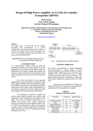
1. Design Of High Power Amplifier At 3.4 GHz For Satellite
Transponder (IRNSS)
Patel Neel K.
Prof. Anil K Sisodia
Ast Prof. Nimesh M Prabhakar
Department of Master Engineering In Communication System Engineering,
L. J. Institute of Engineering and Technology,
Gujarat Technological University,
Ahmedabad, Gujarat
patel.neel2810@gmail.com
Abstract
This paper gives a step-by-step of the design,
simulation and measurement of a Power
Amplifier(PA) operating frequency from 2.5GHz to
4.5GHz. The design of Class A Power amplifier was
performed in Agilent ADS and the performance was
tested with SZA3044Z BJT.
Key Words: RF Power Amplifier, Bipolar Junction
Transistor(BJT), IRNSS, High Gain
I. INTRODUCTION
In a communication satellite serving the earth, the
transponder transforms the received signals into forms
appropriate for the transmission from space to earth. The
transponder may be simply a repeater that amplifies and
frequency signals. In this paper, the technologies of the
major transponder elements are presented and amplifying
devices.
One of the key elements of any spacecraft
transponder is the output transmitter, consisting of a high
power amplifier (HPA) and the associated power supply.
The amplifier is operated at or near saturation (maximum
output power level) to attain a high overall efficiency of
converting dc energy from the power supply into useful
radio frequency (RF) energy that carries information.
The transmitter is required to amplify the
wanted signal without distortions and without other
impairments which would decrease the usefulness of the
signal. Two types of amplifiers (transmitters) are in
common use, electron beam devices (commonly
TWTAs) and solid state power amplifiers (SSPAs). For
the TWTAs, the electrical power supply is often required
to supply a number of high voltages (in the multikilovolt
range), which presents a series of technology and design
challenges. show in fig 1.
Fig 1 – Transponder power amplifier diagram
II. DESIGN APPROACH
The wireless communications in satellite transponder
increasing demands on systems designs. A critical
element in Radio Frequency (RF) front ends is the Power
Amplifier (PA). Main specifications for PA design
include high linearity, better gain and efficiency. This
paper describes the process of designing a single stage
classA Power Amplifier for operation in the 2.5-4.5 GHz
band.
The active device specified for this design was
a Rfmd SZA3044Z BJT. Table I shows the performance
specifications for the designed Power amplifier.
TABLE I
TARGET SPECIFICATION
Parameter Symbol Specification
Frequency range fo 2.5-4.5 GHz
Gain S21 ≥15dB
Input return loss S11 ≤ -10dB
Output return loss S22 ≤ -10dB
Input/output
Impedance
Z0 50Ω
Output power P0 1W
2. III. STABILITY CONSIDERATION
Before PA design, it is important to determine the
stability of the transistor. The stability of an amplifier
is very important in the design and if not taken care,
can create self-oscillation of the device due to
reflected wave.
Amplifier is not reliable when it is unstable
condition. The stability of a circuit is characterized by
stability factor. The transistor is stable when K>1 and
∆<1.
Fig 2- Stability simulation
After simulation ,the value of stability factor (K) is
6.673(K>1). So, now the transistor is in stable region.
STABILITY FACTOR, K (SHOULD BE >1)
Fig 3- Stability result
IV. MATCHING NETWORK DESIGN
Impedance matching is required to maximize the
power transfer and minimize the reflections. Smith
chart is used for impedance matching. According to
maximum power transfer theorem, maximum power
delivered to the load when the impedance of load is
equal to the complex conjugate of the impedance of
source (ZS=ZL*).
A.INPUT MATCHING NETWORK
The first set of measurements we are taken
for S11 with the device mounted on the board and
biased, but without matching networks. These
measurements were de-embedded in ADS to obtain
the input impedance at the device terminal.
Fig 4- Input matching network
The circuit was then conjugate matched
from this point to the 50Ω impedance presented by
the trace line. The input matching network shown in
Figure 3, was designed using the Smgamma function
in ADS.
The input matching network uses a series
inductor and parallel capacitor. A parallel capacitor is
the value of 0.5pF and series inductor is the value of
1.4nH. A lumped component matching at 3.4GHz is a
viable option but it would not provide the option of
tuning.
Fig 5- Input impedance result
B. OUTPUT MATCHING NETWORK
To design the output matching network, S22 of the
biased, unmatched system was measured and de-
embedded back to the device terminals. Simulations
were then performed to determine the impedance
presented to the drain that would maximize small
signal gain. The matching network was designed in
the same fashion as the input matching network.
This method gave several different optimal
load impedances, indicating that trade-offs would be
necessary to meet all specifications. The output
matching network shown in Figure 5, was designed
using the Smgamma function in ADS.
3. Fig 6- Output matching network
The output matching network uses a series
inductor and parallel capacitor. A parallel capacitor is
the value of 2.85 pF and series inductor is the value
of 0.5nH. A lumped component matching at 3.4GHz
is a viable option but it would not provide the option
of tuning.
Fig 8- Output impedance result
INPUT RETURN LOSS AND OUTPUT
RETURN LOSS
Fig 9-S11
Fig 10- S22
4. Fig 11- S21 Gain
Fig-14 S21 After Baising Gain
Fig 13 S11 After Biasing
Fig-15 After Baising Stability factor
5. VI. MEASURED RESULTS
The complete schematic of the
power amplifier is shown in the Figure.
The performance results are using the
Impedance Matching. Then After
Matching the Most Important is Biasing
Network . All Results Are including in
below Table.
VII. HARMONIC DISTORTION
Harmonic distortion means the
presence of frequency components in the
output waveform which are not present in
the input signal. Due to non linearity
amplification of all the portion of positive
and negative half cycles is not same and it
causes the output waveform to be different
from input waveform. When the input signal
is applied to a transistor the non-linear
characteristics causes the positive half of the
signal to be amplified more than negative
half cycle.
Due to this output signal signal
contains fundamental frequency components
and some undesired frequency components,
which are integral multiple of input signal
frequency. These additional frequency
components are called harmonics. Hence the
output is said to be distorted, this is called
harmonic distortion.
VIII. SECOND ORDER HARMONICS:
For linear amplification, the dynamic
transfer characteristics relation b/w Ib and Ic which is
known as transfer characteristic must be linear. To
evaluate the second harmonic distortion assume that
the dynamic transfer characteristics of the transistor is
parabolic (non-linear ) in nature rather than (linear).
Parameter Symbol Specification Measured results
After Impedance
Matching
Measured
results
After Biasing
Network
Gain S21 ≥15dB 26.412dB 27.064dB
Input return loss S11 ≤ -10dB -39.873dB -15.440dB
Output return loss S22 ≤ -10dB -49.342dB -15.725dB
Input/output
Impedance
Z0 50Ω 50Ω 50Ω
6. IX. HARMONIC BALANCE IN ADS:
Fig 17 dBm(vout)
Fig 19 1st
Harmonic
Fig 18 Gain Harmonic
Fig 20 1st
& 3rd
Harmonic
7. X. CONCLUSION
The power amplifier presented here doesn’t
meet many of the required specifications. Still a
Stable Power amplifier with certain loss of power has
been designed with proper matching networks. But
working on this design provided a lot on insight into
design of power amplifiers and the problems faced
when the specifications require designs to be
extremely competitive in terms of performance.
The choice of transistor in this power
amplifier has influenced the design specifications in
an unexpected manner. To make a power amplifier
utilizing this device, a wide variety of matching
networks should be explored along with an
appropriate device modelling in ADS. Also Complete
the Impedance Matching , Biasing Network ,
Harmonics Balance.
XI. ACKNOWLEDGEMENT
The Author thanks Prof.A.K Sisodia & Ast Prof.
Nimesh M. Prabhakar from L.J.Institute of
Engineering and Technology for technical discussion
& processing support without whom this paper would
never be complected.
XII. REFERENCES
[1] Tomohiro Senju, Takashi Asano, Hiroshi
Ishimura Microwave Solid-state Department “A
VERY SMALL 3.5 GHz 1 W MMIC POWER
AMPLIFIER WITH DIE SIZE REDUCTION
TECHNOLOGIES” Komukai Operations Toshiba
Corporation, Komukai, Toshiba-cho, Saiwai-ku,
Kawasaki 2 12-858 1, Japan-2001 IEEE, pp. 070-073
,ISBN:0-7803-7161-5/01.
[2] Kevin W. Kobayashi, YaoChung Chen, Ioulia
Smorchkova, Roger Tsai,Mike Wojtowicz, and Aaron
Oki “A 2 Watt, Sub-dB Noise Figure GaN MMIC
LNA-PA Amplifier with Multi-octave Bandwidth
from 0.2-8 GHz” 2007 IEEE - SIRENZA
MICRODEVICES, pp.619 -622,ISBN:1-4244-0688-
9/07.
[3] Paul saad, christian fager, hossein mashad nemati,
haiying cao, herbert zirath and kristoffer andersson ”
A highly efficient 3.5 GHz inverse class-F GaN
HEMT power amplifier” European Microwave
Association International Journal of Microwave and
Wireless Technologies, 2010, 2(3-4), pp.317–
332,DOI:10.1017.
[4] Bilkent University, Nanotechnology Research
Center, Bilkent, Ankara, Istanbul Technical
University, Electrical & Electronics Faculty,Maslak,
Istanbul, Turkey ” Design of High Power S-Band
GaN MMIC Power Amplifiers for WiMAX
Applications” 2011 IEEE, pp.01-04,ISBN:978-1-
4244-6051-9/11.
[5] Ahmed Sayed, Georg Boeck Microwave
Engineering, Berlin University of Technology
Einsteinufer 25, 10587 Berlin, Germany ” 5W
Highly Linear GaN Power Amplifier with 3.4 GHz
Bandwidth”European Microwave Integrated Circuits
Conference 2007 EuMA , pp.631 – 634,ISBN:978-2-
87487-002-6.
[6] U. K. Mishra, P. Parikh, and Y.-F. Wu,
“AlGaN/GaN HEMTs−An overview of device
operations and applications”, Proceedings of the
IEEE, vol. 90, no. 6, June 2002, pp. 1022–
1031,ISBN:2230-7109.
[7] U. K. Mishra, L. Shen, T. E. Kazior, and Y.-F.
Wu, “GaN-Based RF Power Devices and
Amplifiers”, Proceedings of the IEEE, vol. 96, no. 2,
February 2008, pp. 287 – 305,ISBN:2230-9543.
[8] S. Keller et al., “Gallium Nitride Based High
Power Heterojunction Field Effect Transistors:
Process Development and Present Status at UCSB”,
IEEE Transactions on Circuits and Systems, vol. 48,
no. 3, March 2001, pp. 552 – 559,ISBN:2278-0181.
[9] U.Schmid et al., “GaN devices for communication
applications: evolution of amplifier architectures”,
International Journal of Microwave and Wireless
Technologies, Cambridge University Press and the
European Microwave Association, 2010, pp. 85–
93,DOI:10.1088/1674-4926/32/9/094003.
[11] Nemati, H.; Fager, C.; Thorsell, M.; Herbert, Z
“High-efficiency LDMOS power-amplifier design at
1 GHz using an optimized transistor model”. IEEE
Trans. Microw. Theory Tech., 57 (7) (2009), pp.
1647–1654,ISSN:3840-7001.
[12] Rollett, J. “Stability and power-gain invariants of
linear two ports”. IEEE Trans. Circuit Theory, 9 (1)
(2010), pp. 29–32,ISBN:978-1-4673-1088-8/12.
[13] Kim, J.; Konstantinou, K.”Digital predistortion
of wideband signals based on power amplifier model
with memory”. Electron. Lett., 37 (2001), pp. 1417–
1418, ISSN:0-7803-8331-1/04.
[14] Nagy, W.; Brown, J.; Borges, R.; Singhal, S.
“Linearity characteristics of microwave-power GaN
HEM”. IEEE Trans. Microw, 51 (2) (2012), pp.660–
664, ISSN:0018-9480.