Downloaded 552 times


Compressed air systems are vital for numerous industrial applications, utilizing air compressors to convert low-pressure air into high-pressure air for operations ranging from manufacturing to pneumatic controls. Various types of compressors, including positive displacement and dynamic compressors, are used based on specific flow and pressure requirements, with features such as different pressure ratios, maintenance needs, and efficiency levels. The document also covers essential components of compressed air systems, including air filters, dryers, and receivers, emphasizing the importance of air quality and efficient performance.
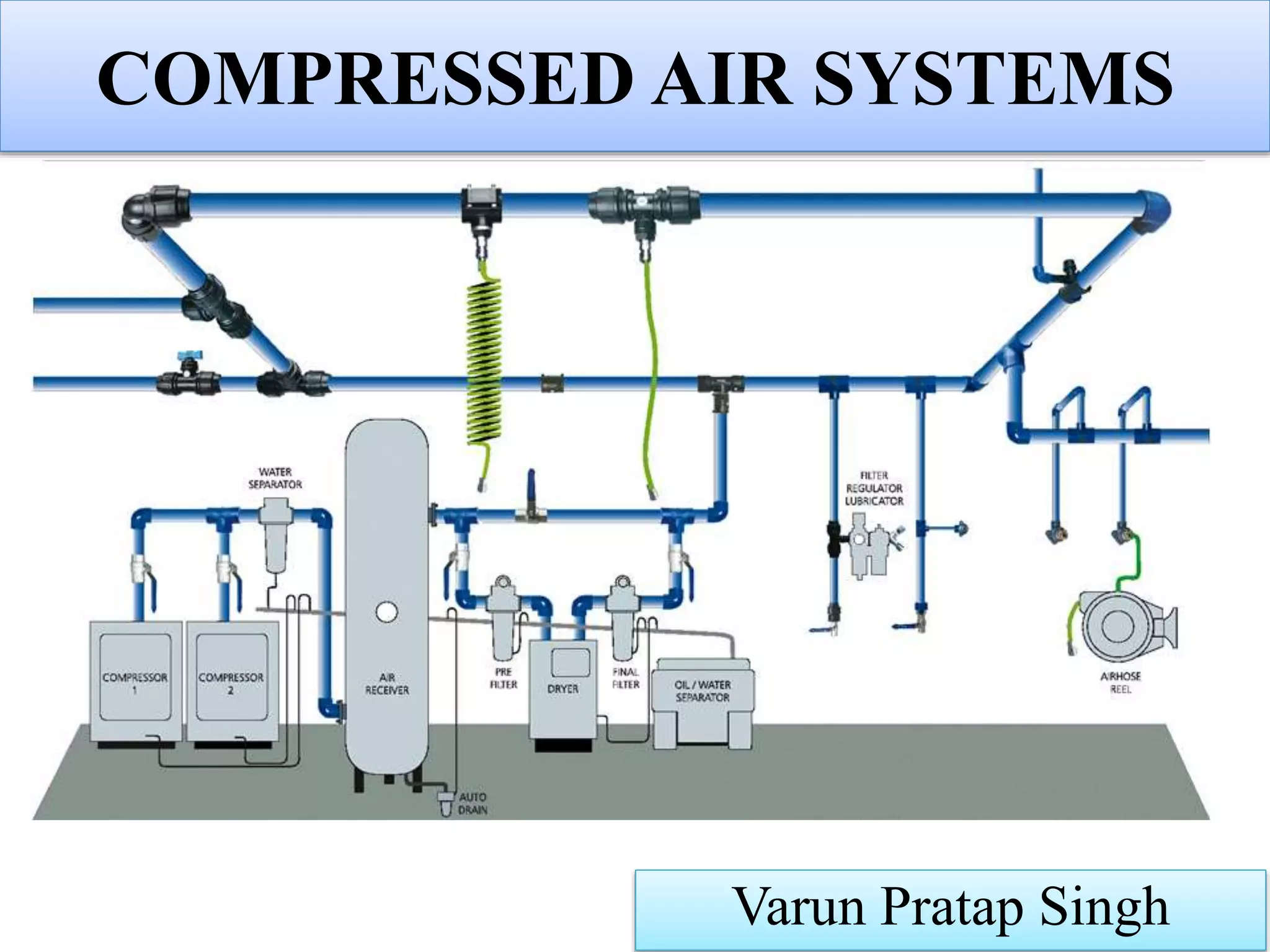
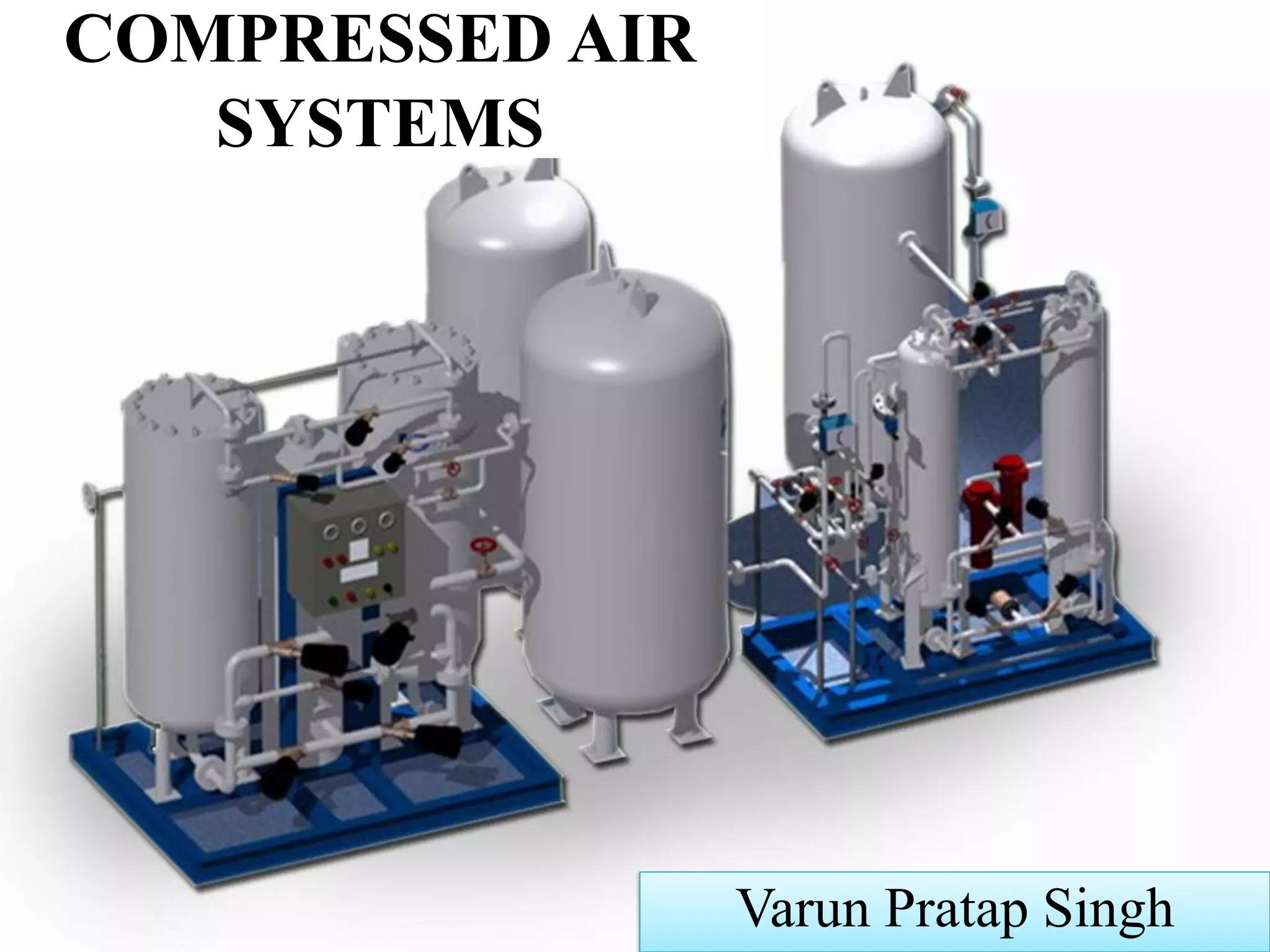
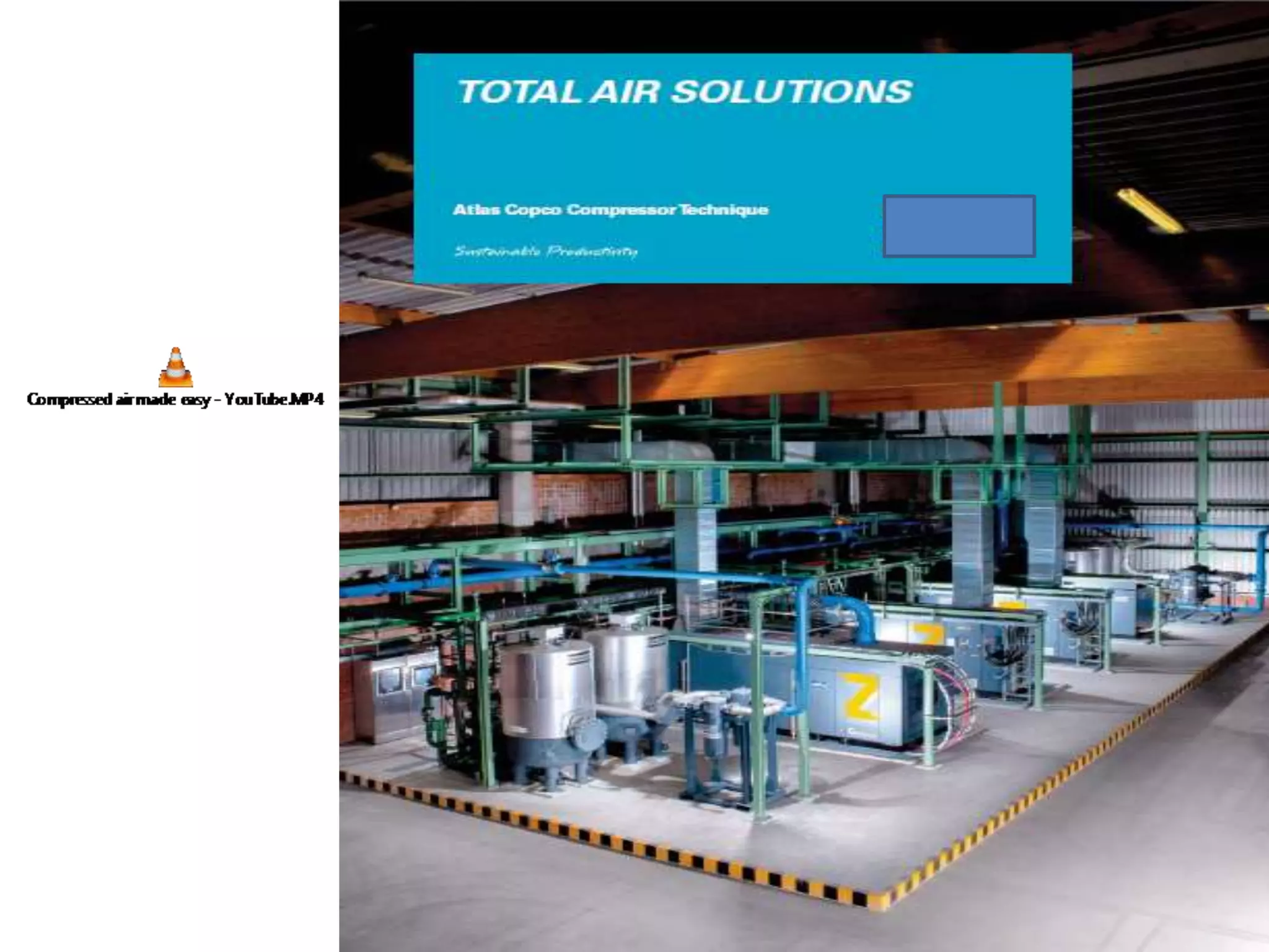
Introduction to compressed air systems, introducing their significance in various industries.
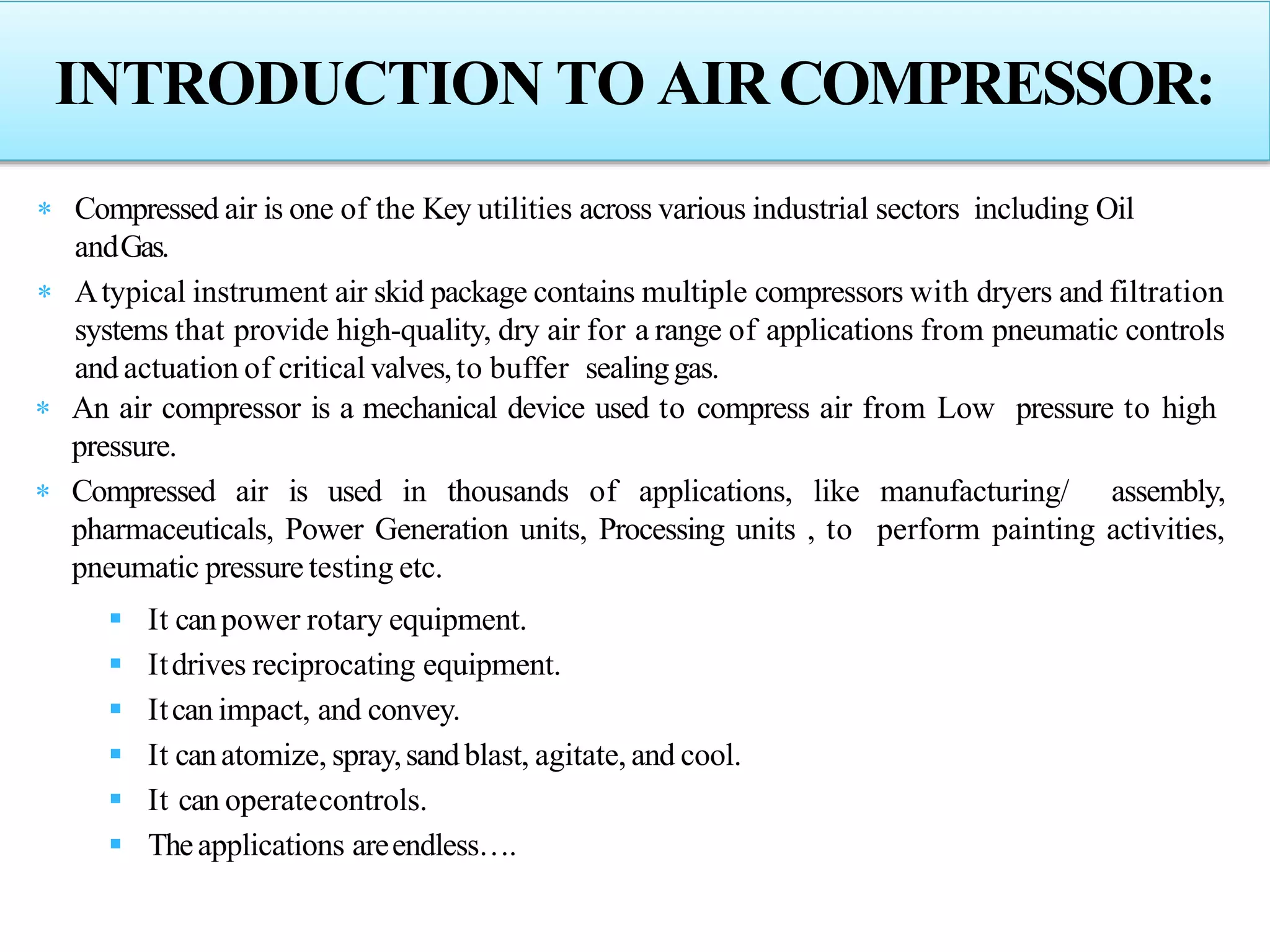
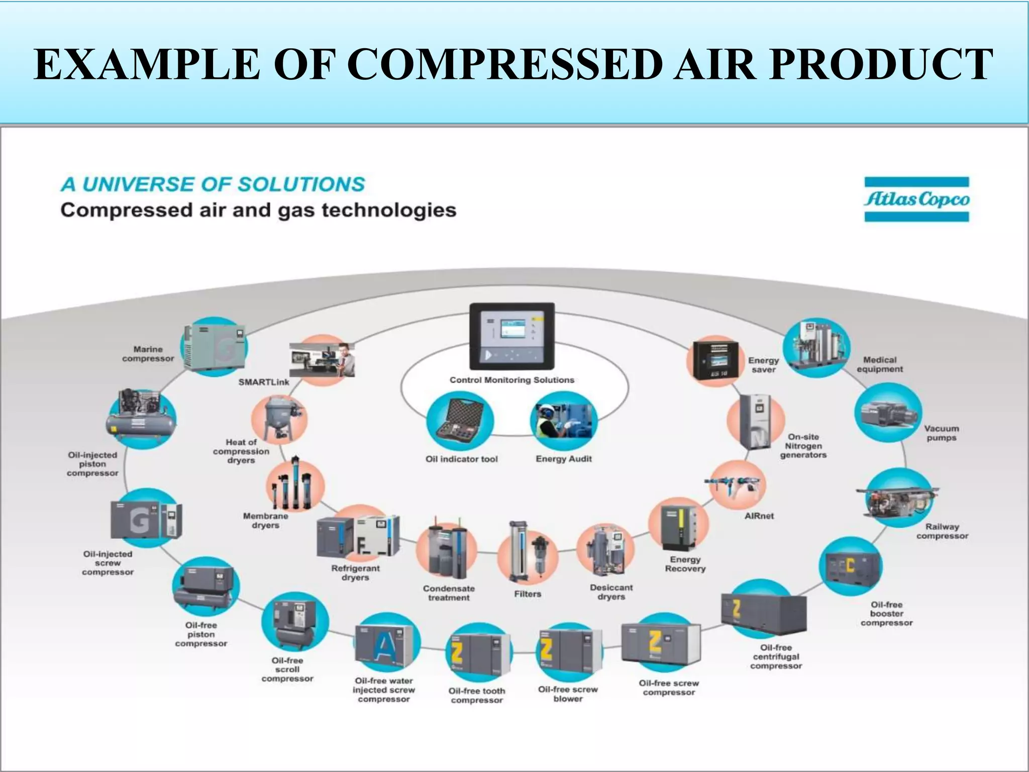
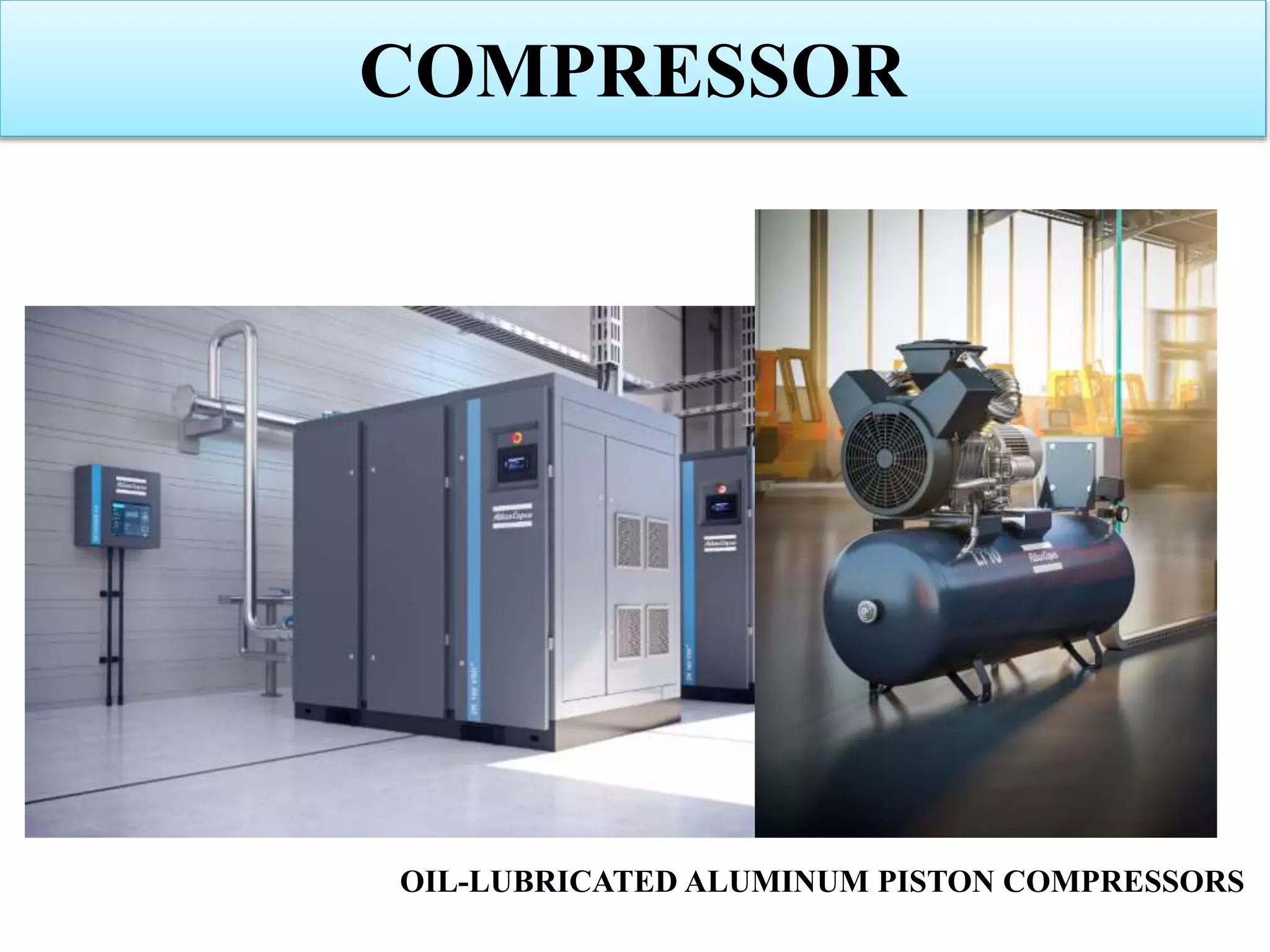
Discusses functionality, applications, and importance of air compressors in multiple setups.
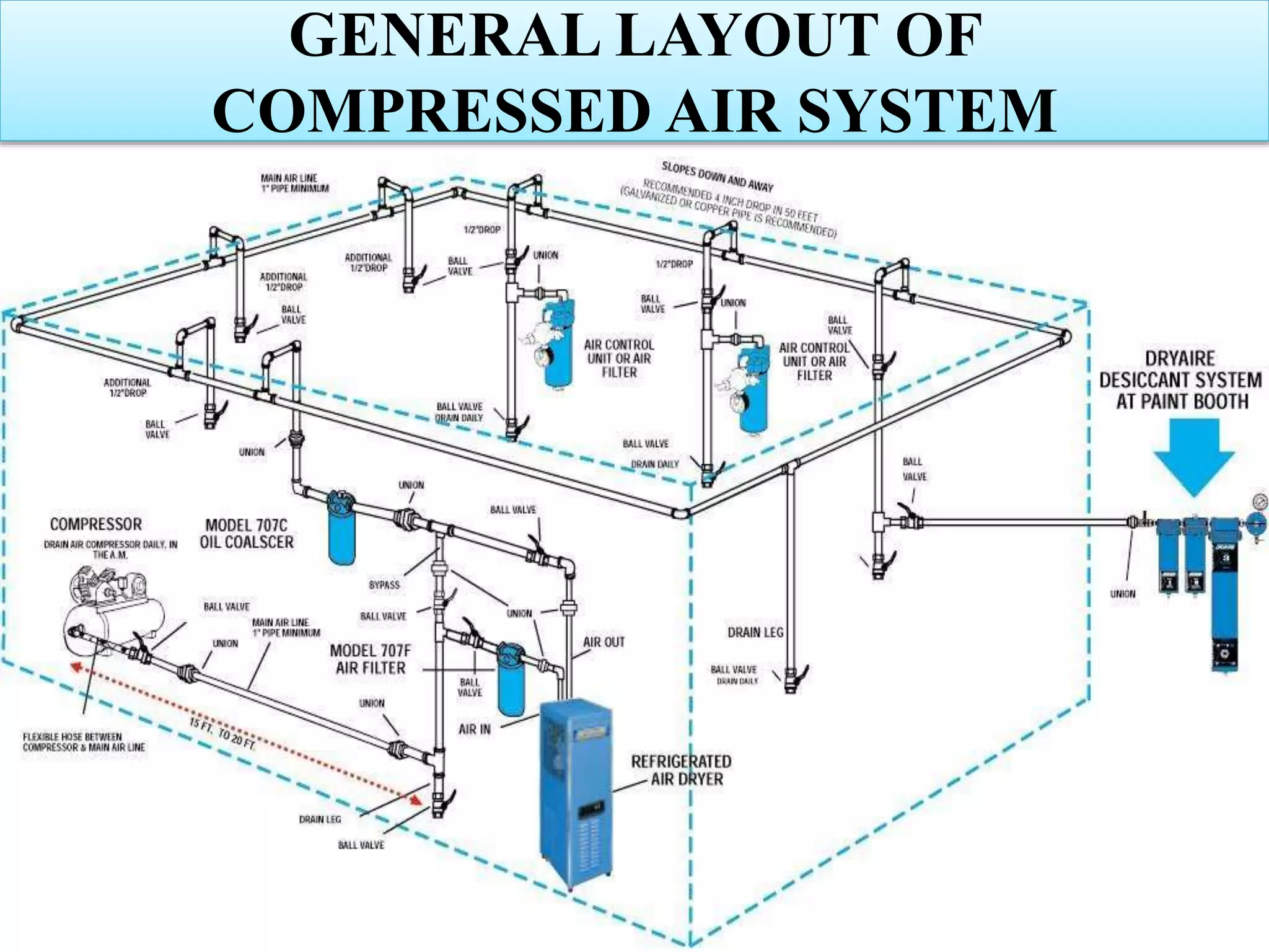
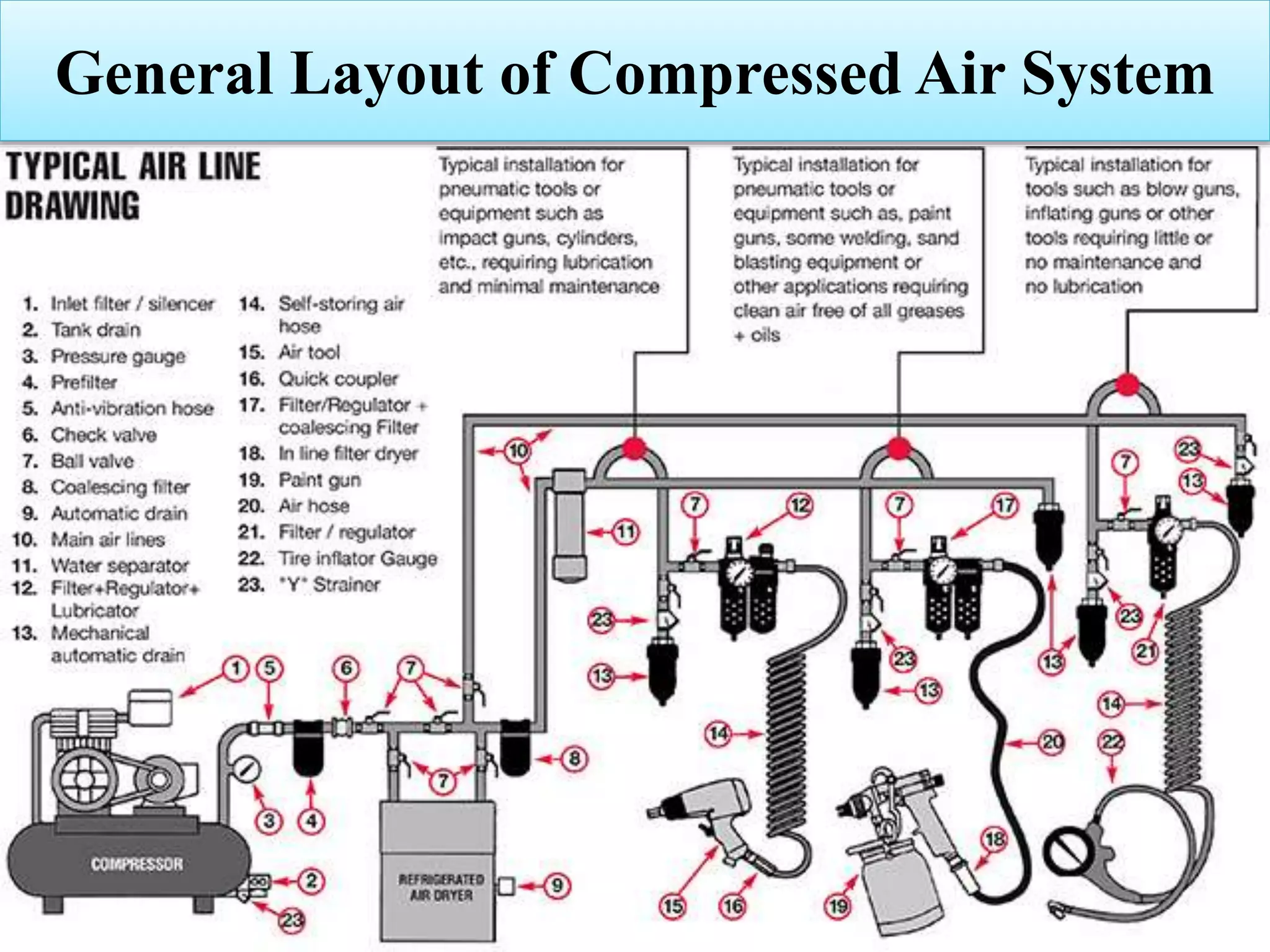
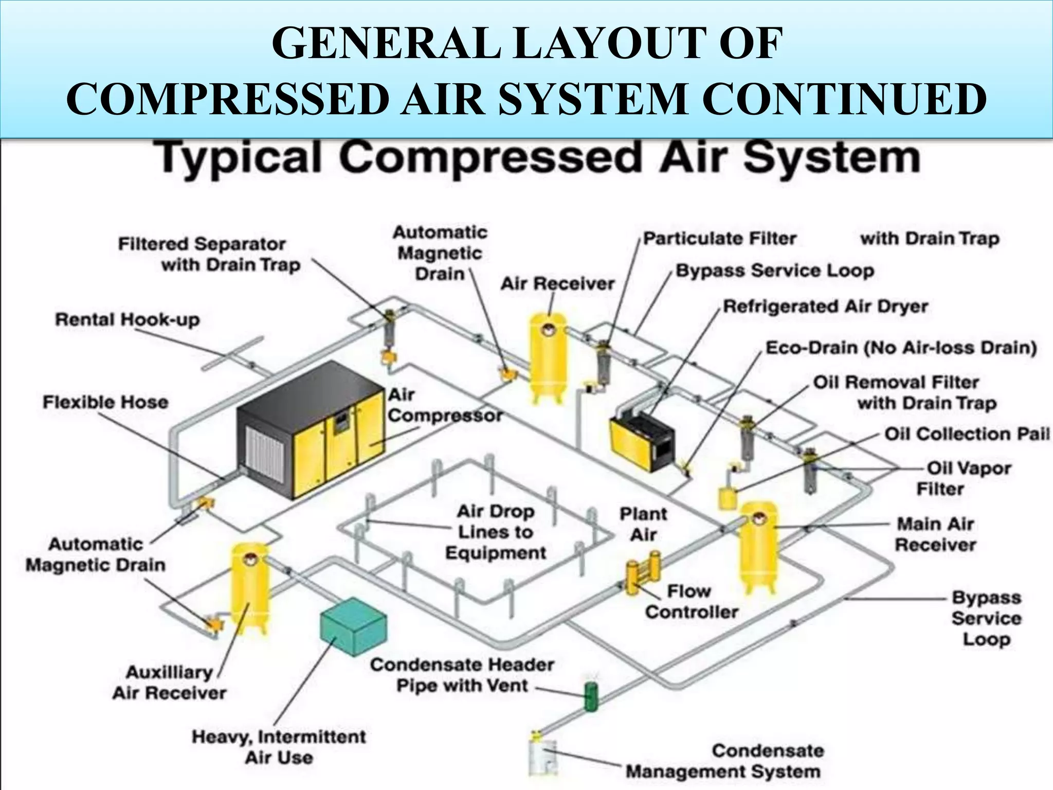
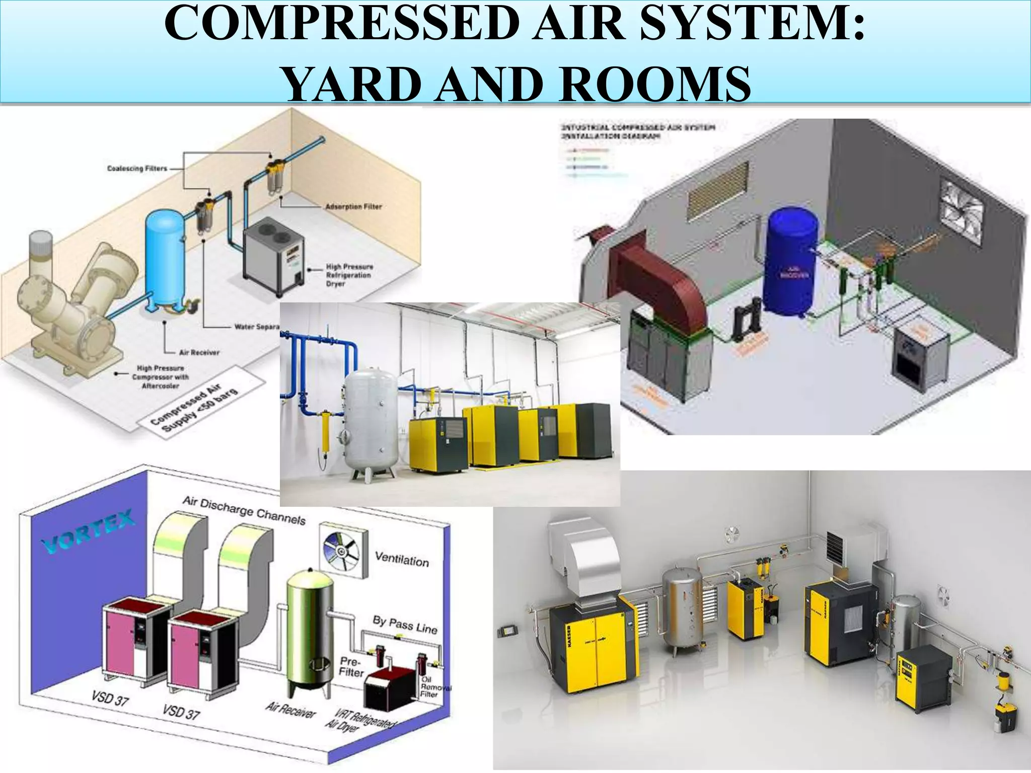
General layout of compressed air systems with emphasis on design and configuration.
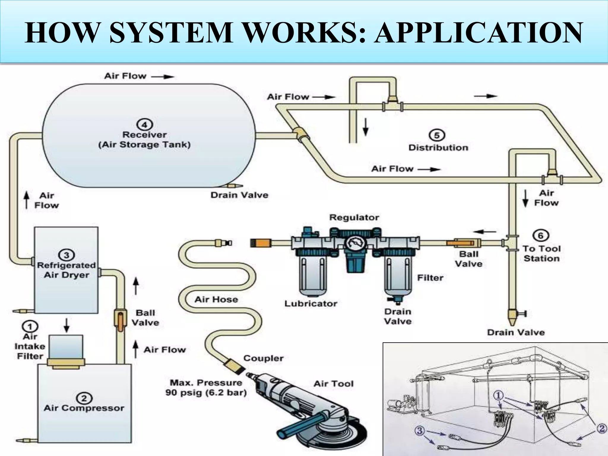
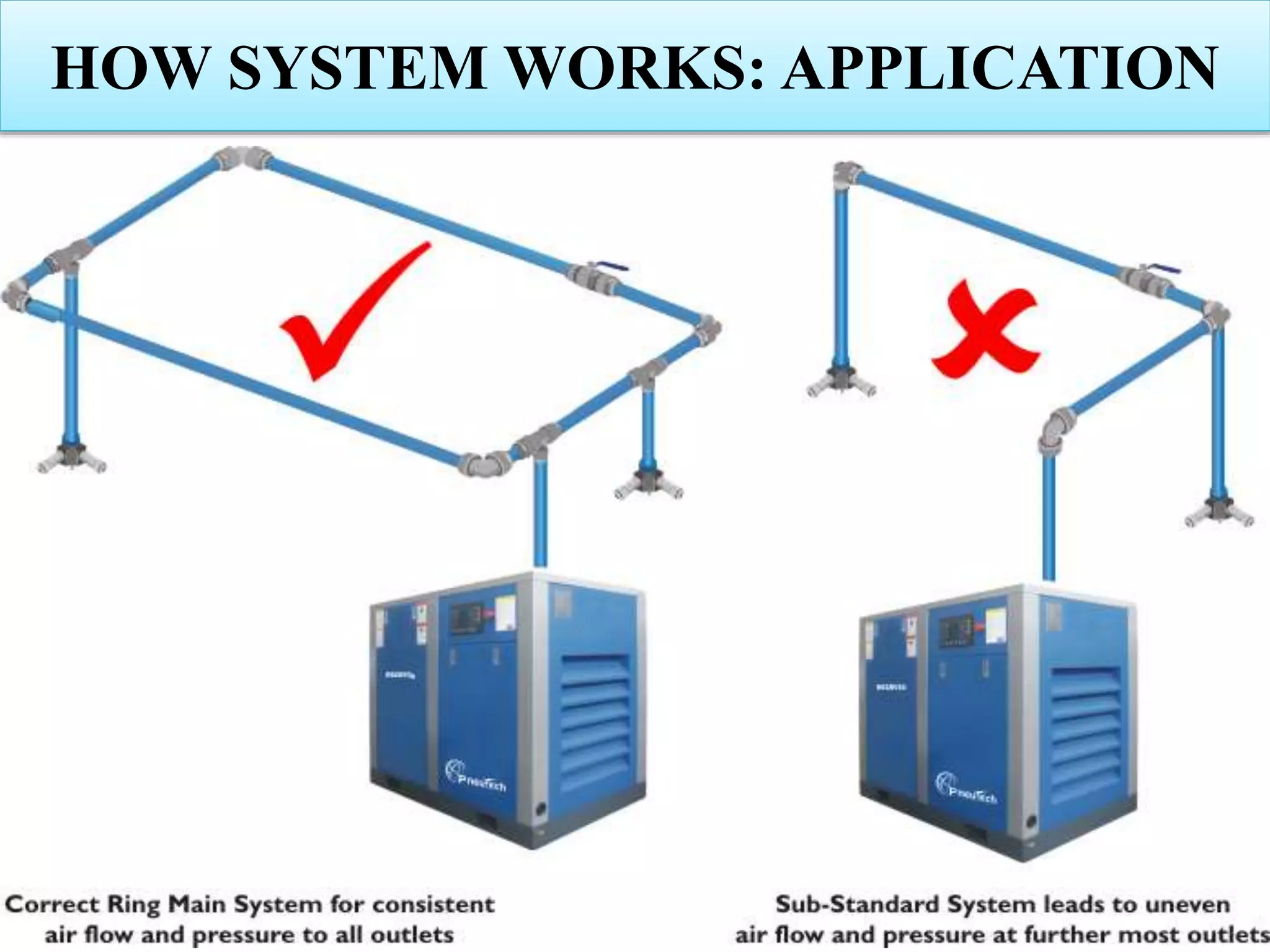
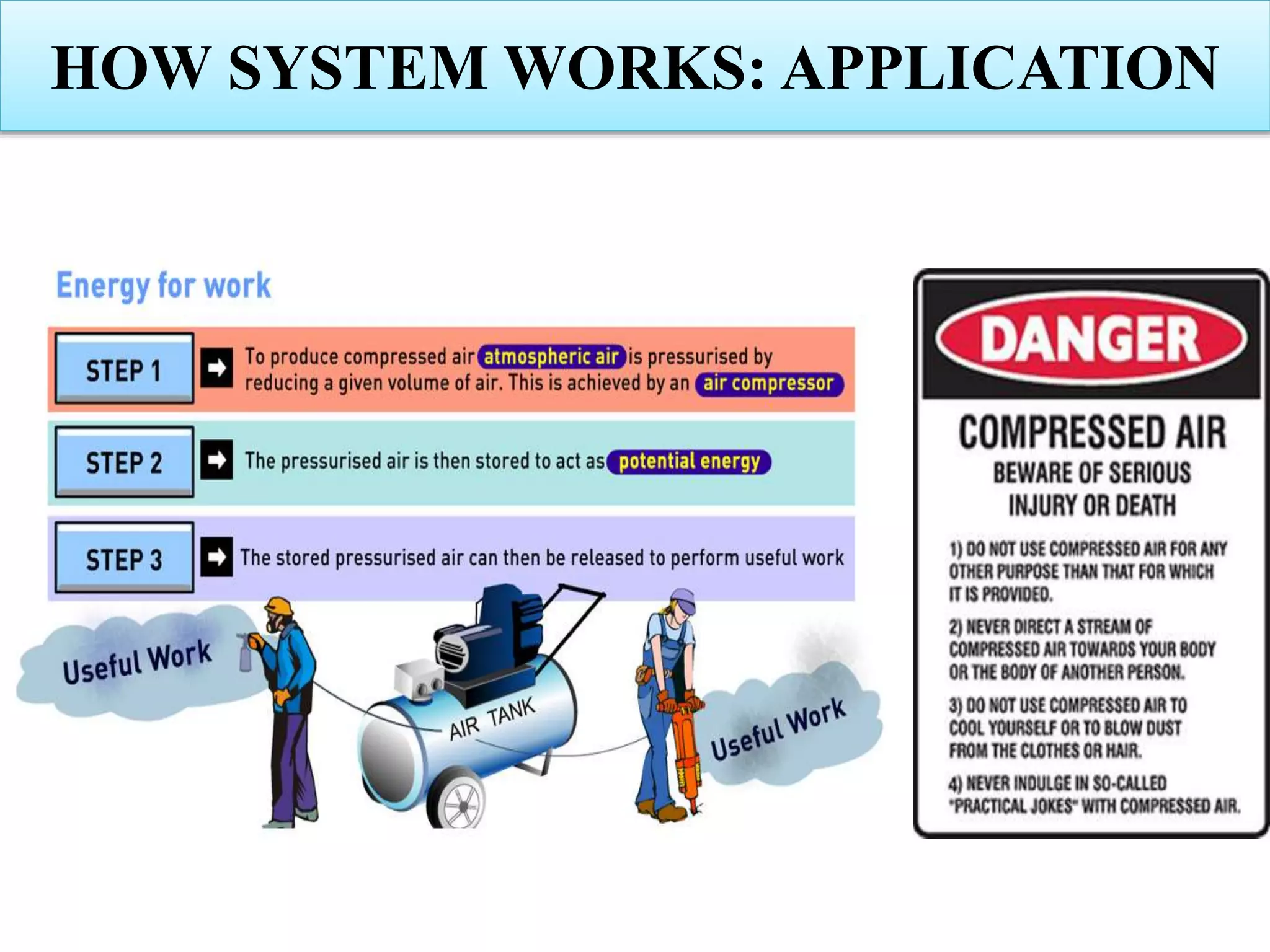
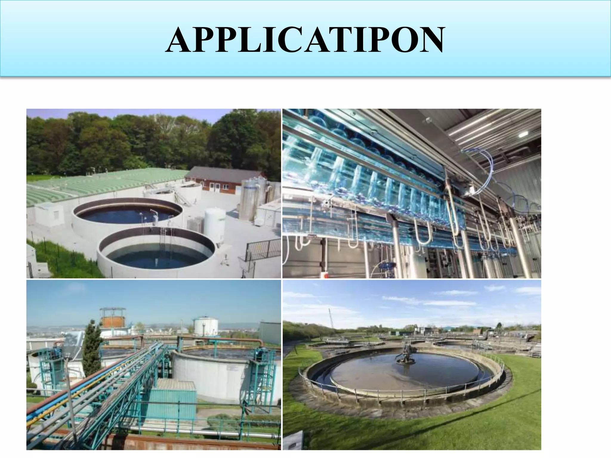
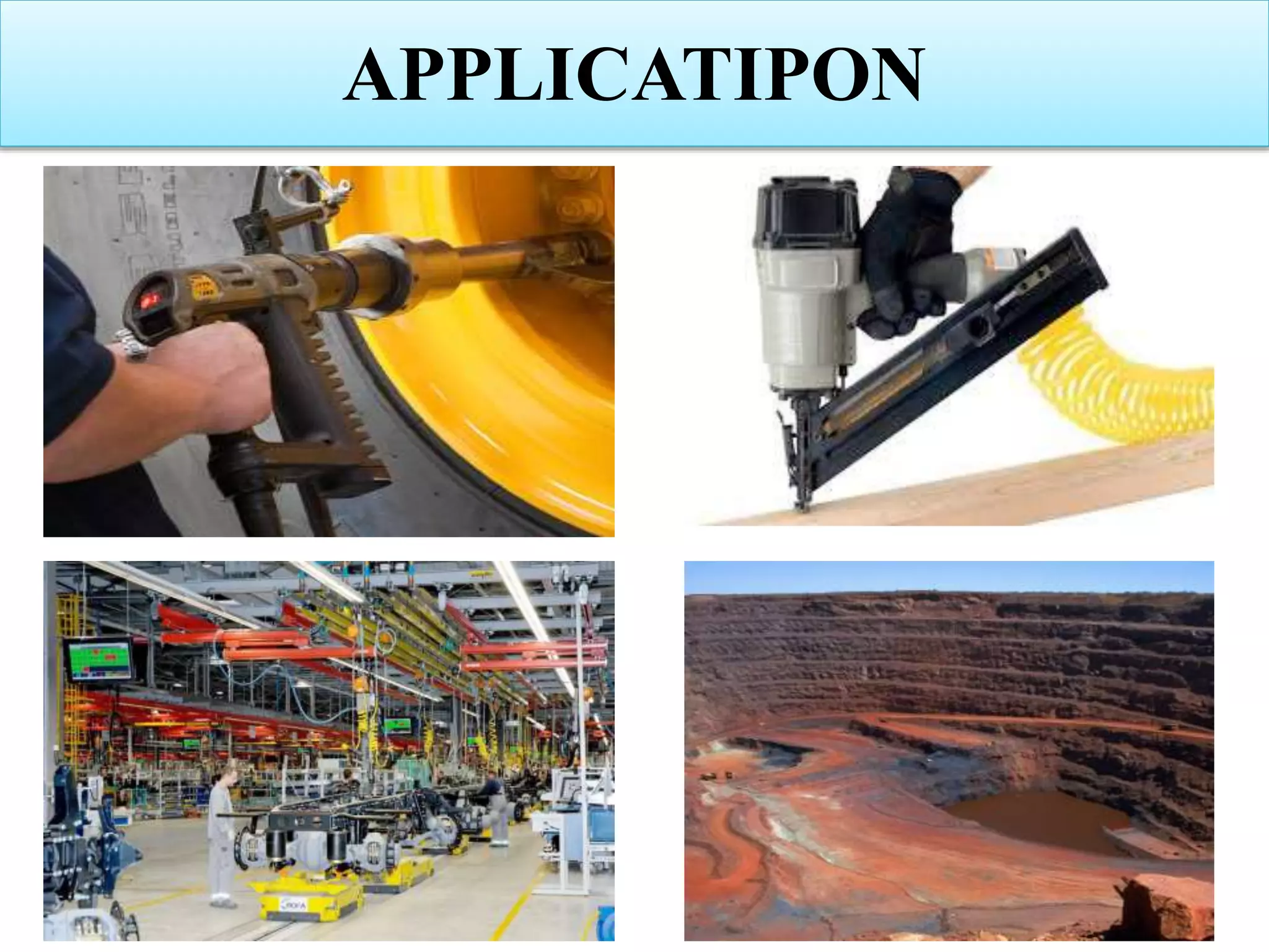
Explains how compressed air systems work and their diverse industrial applications.
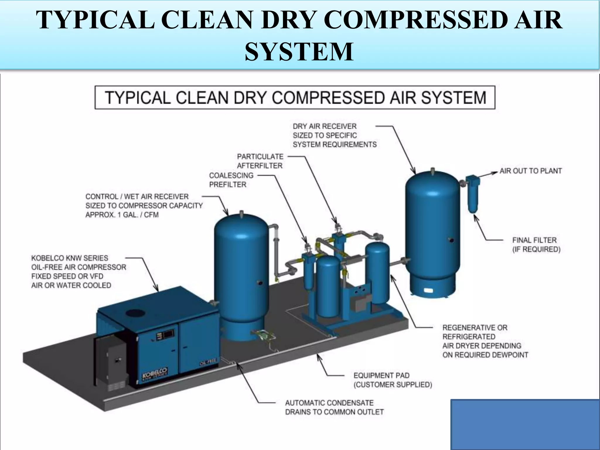
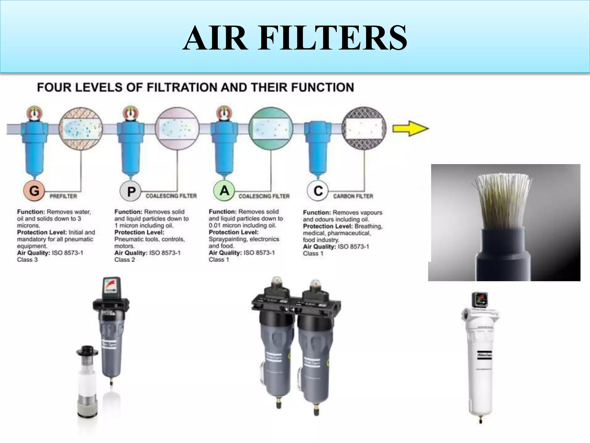
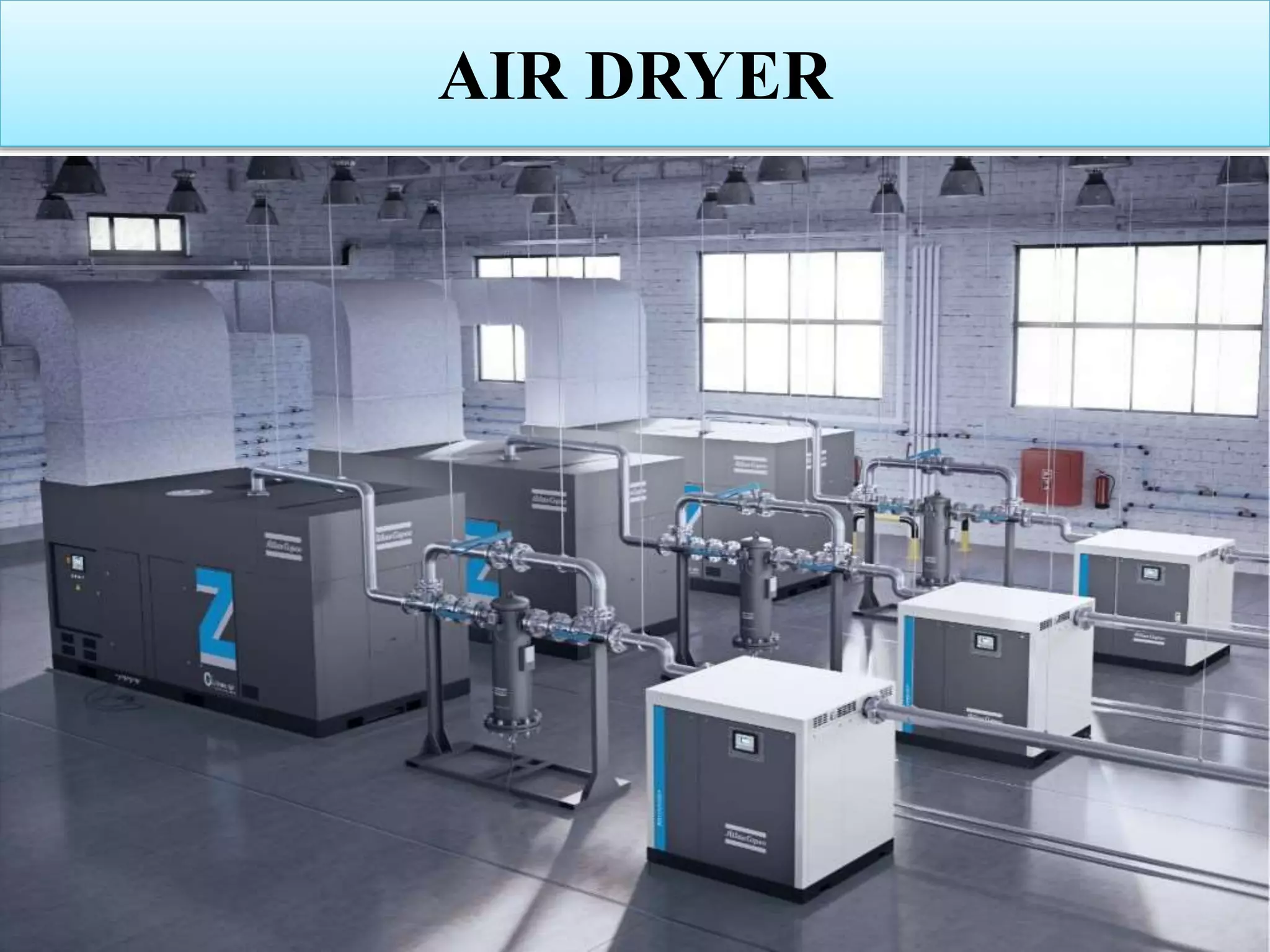
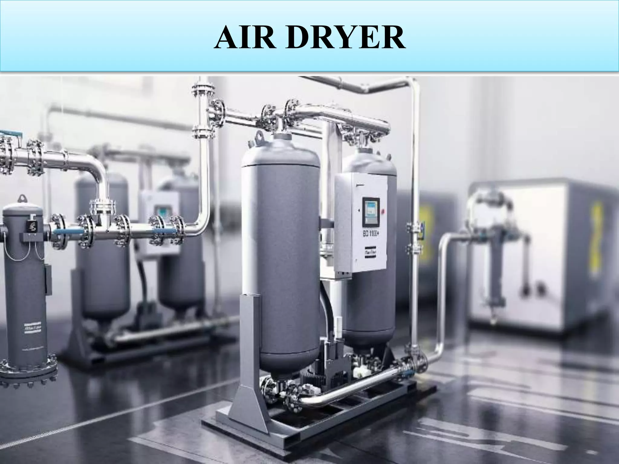
Description of components and configuration in a typical clean dry compressed air systems.
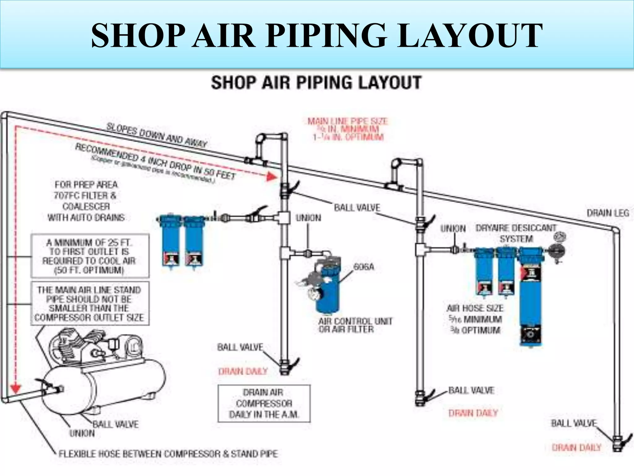
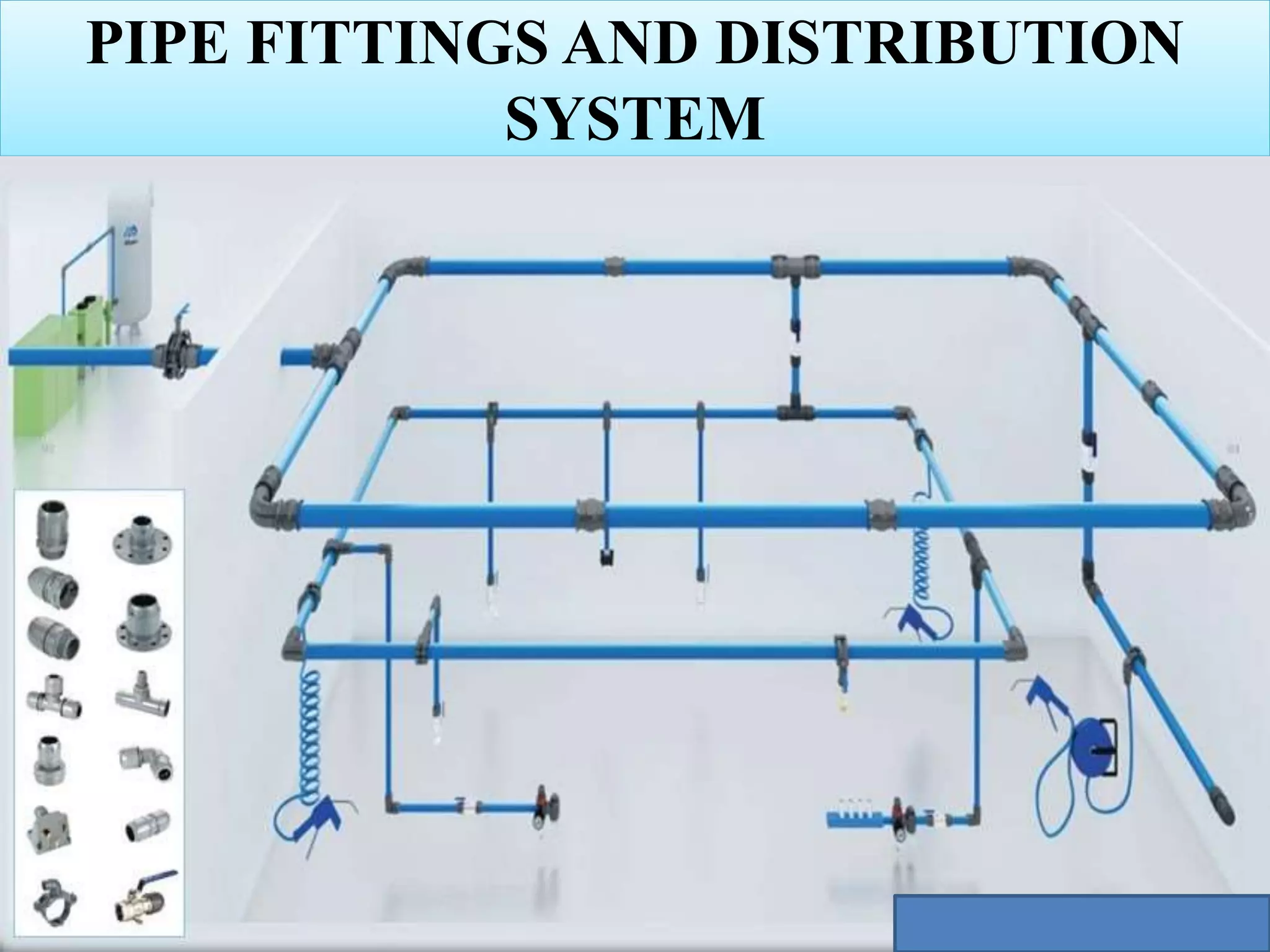
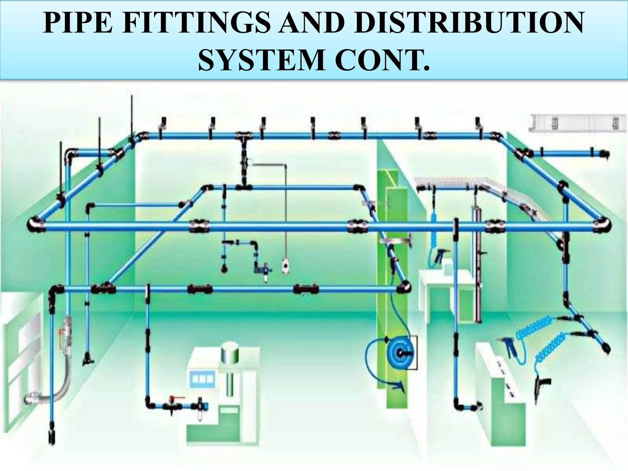
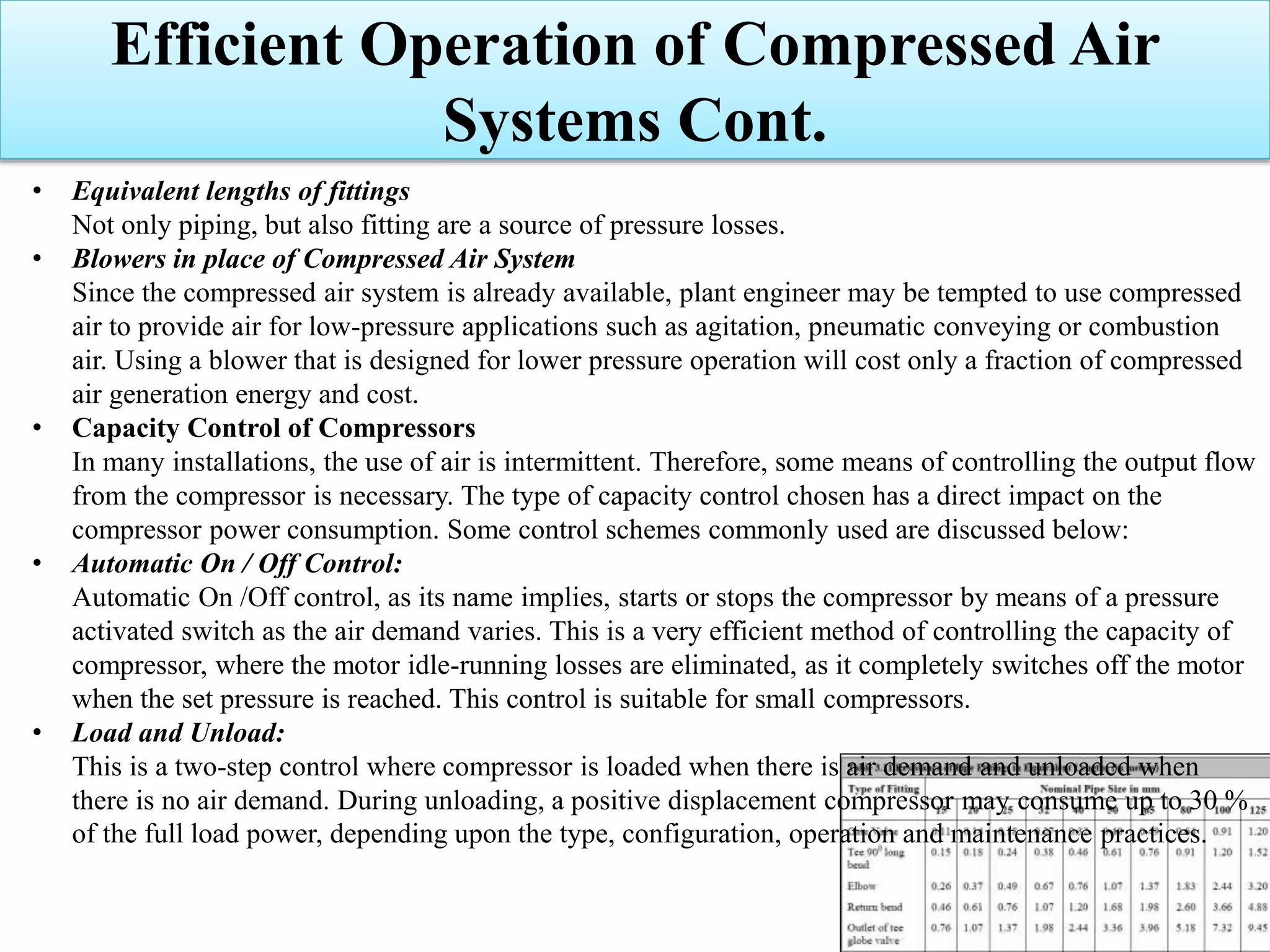
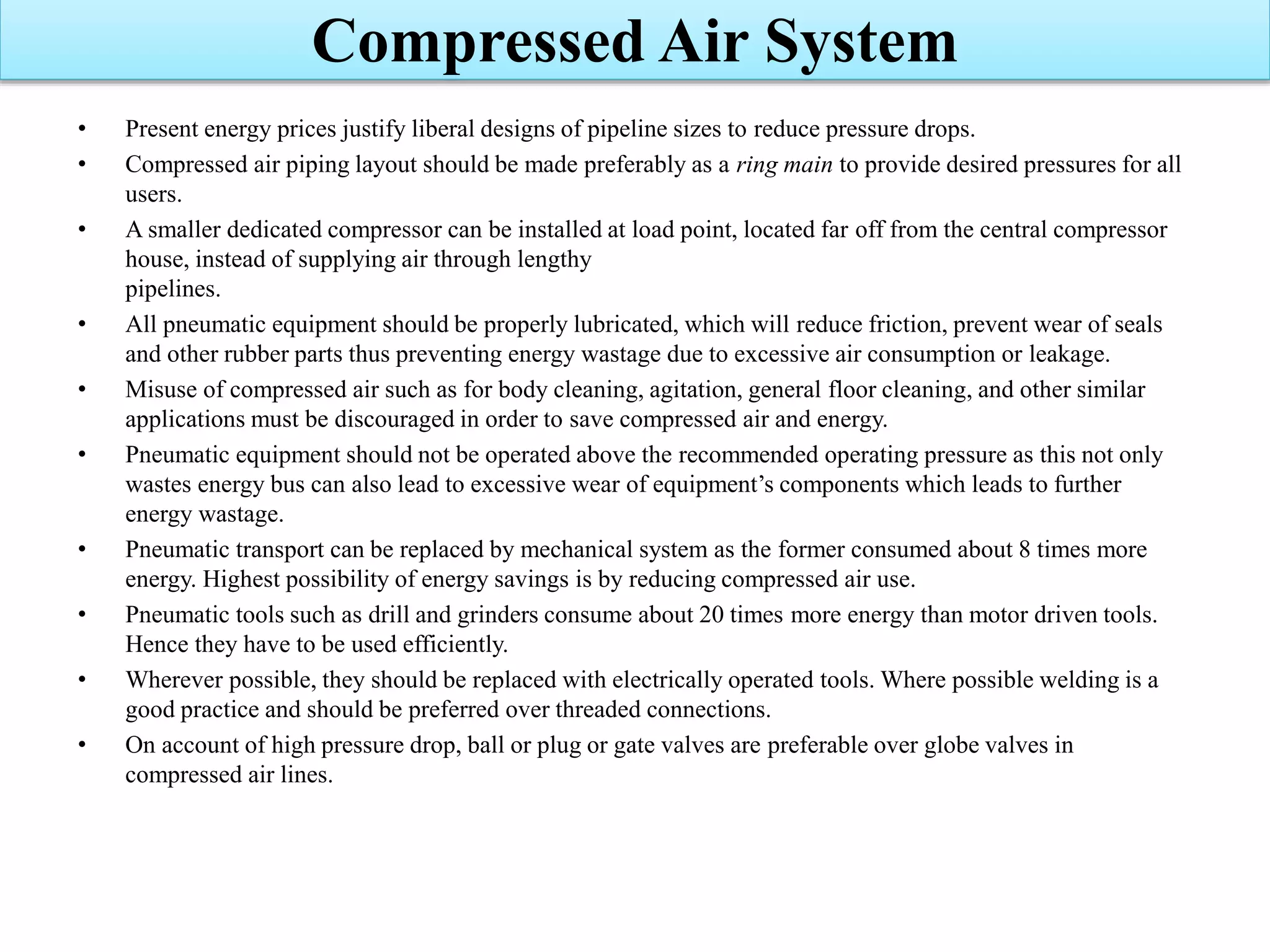
Details on shop air piping layout and the types of pipe fittings in the distribution system.
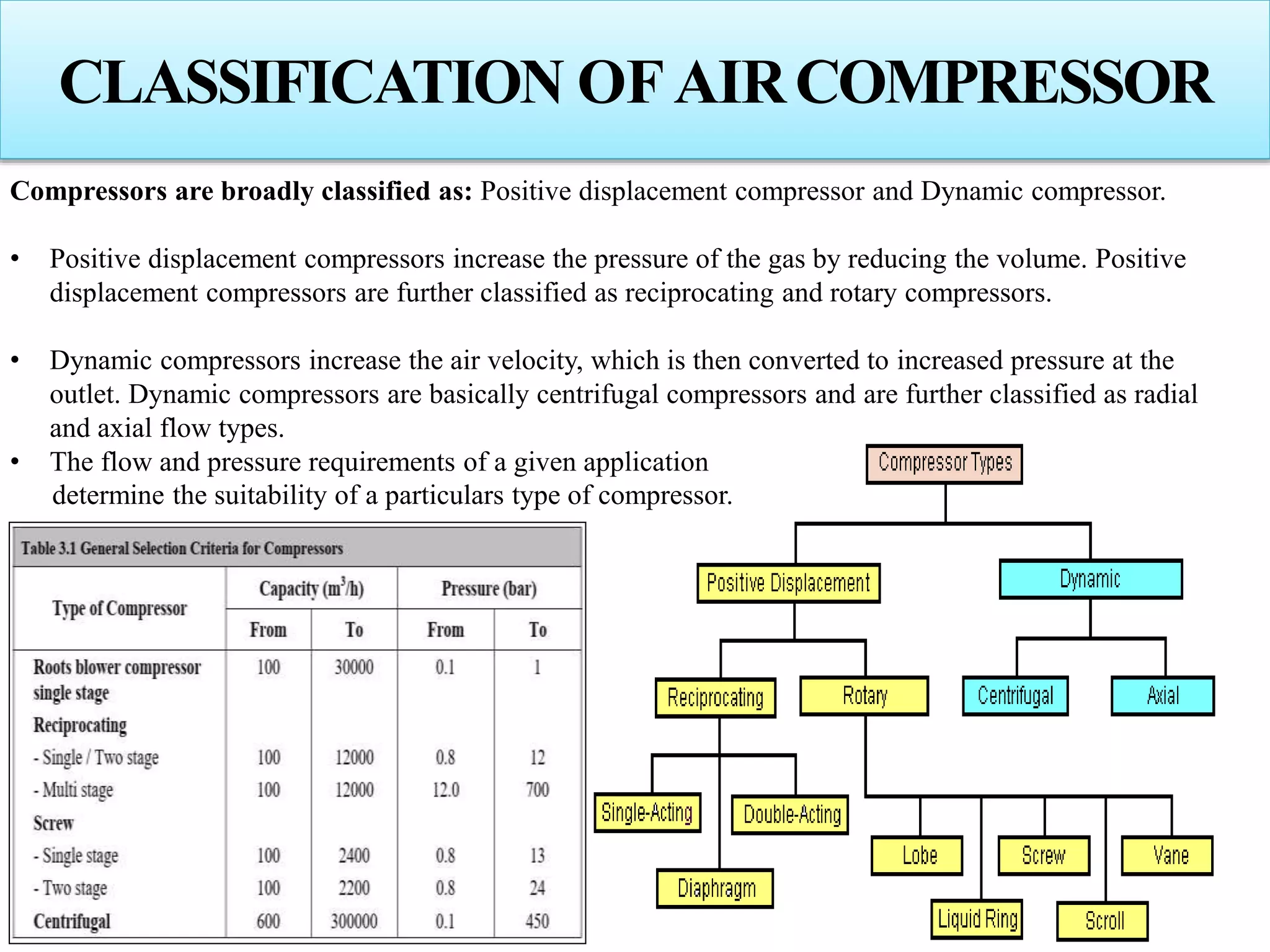
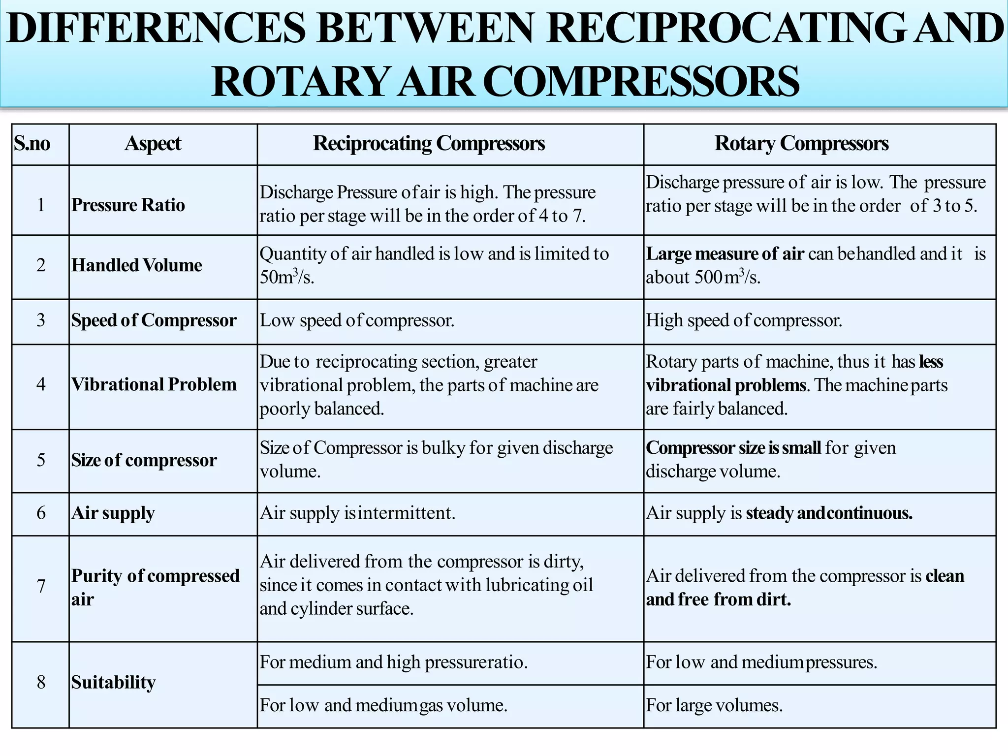
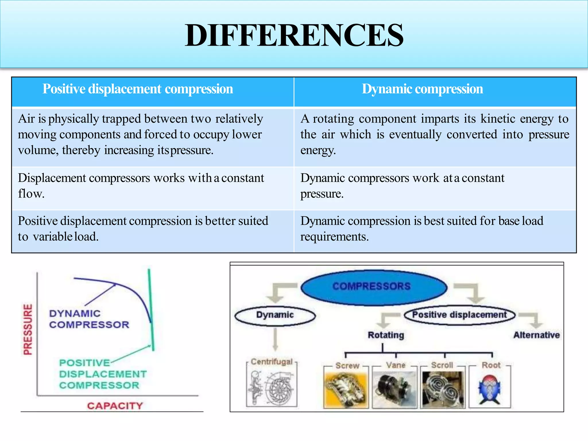
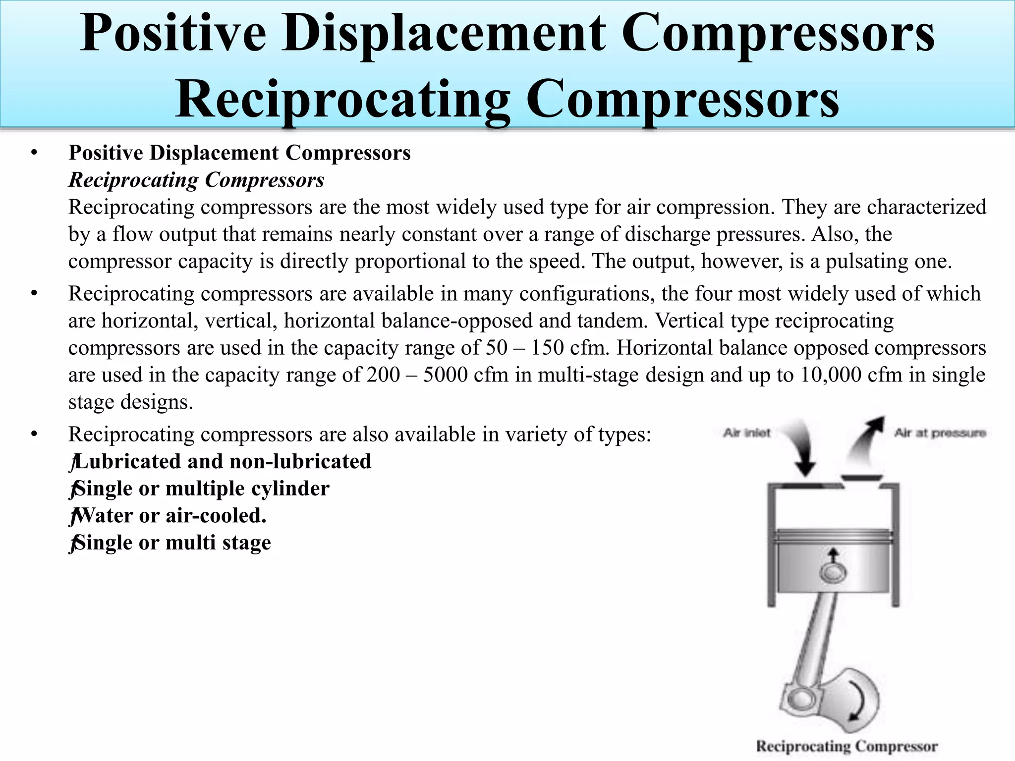
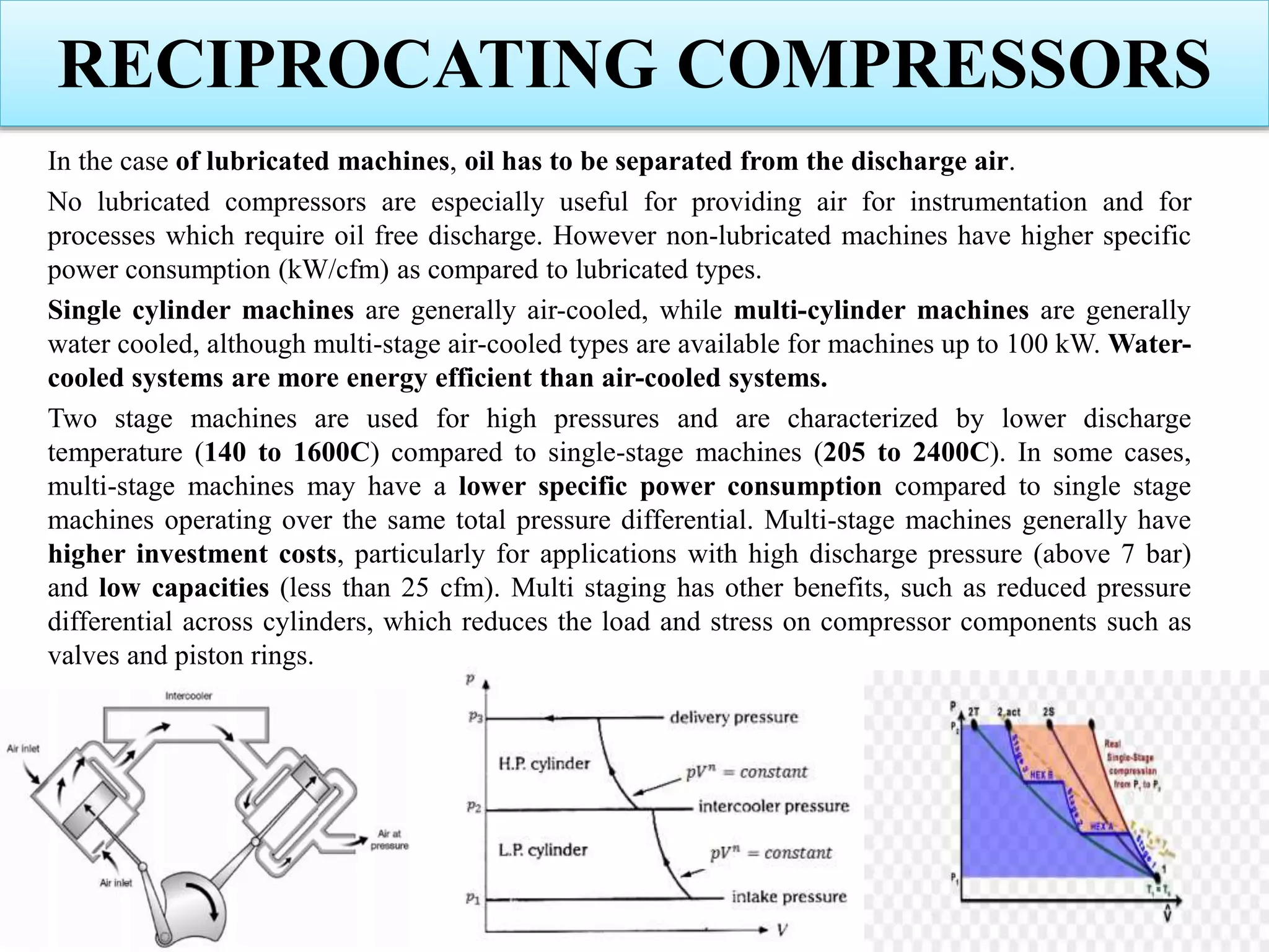
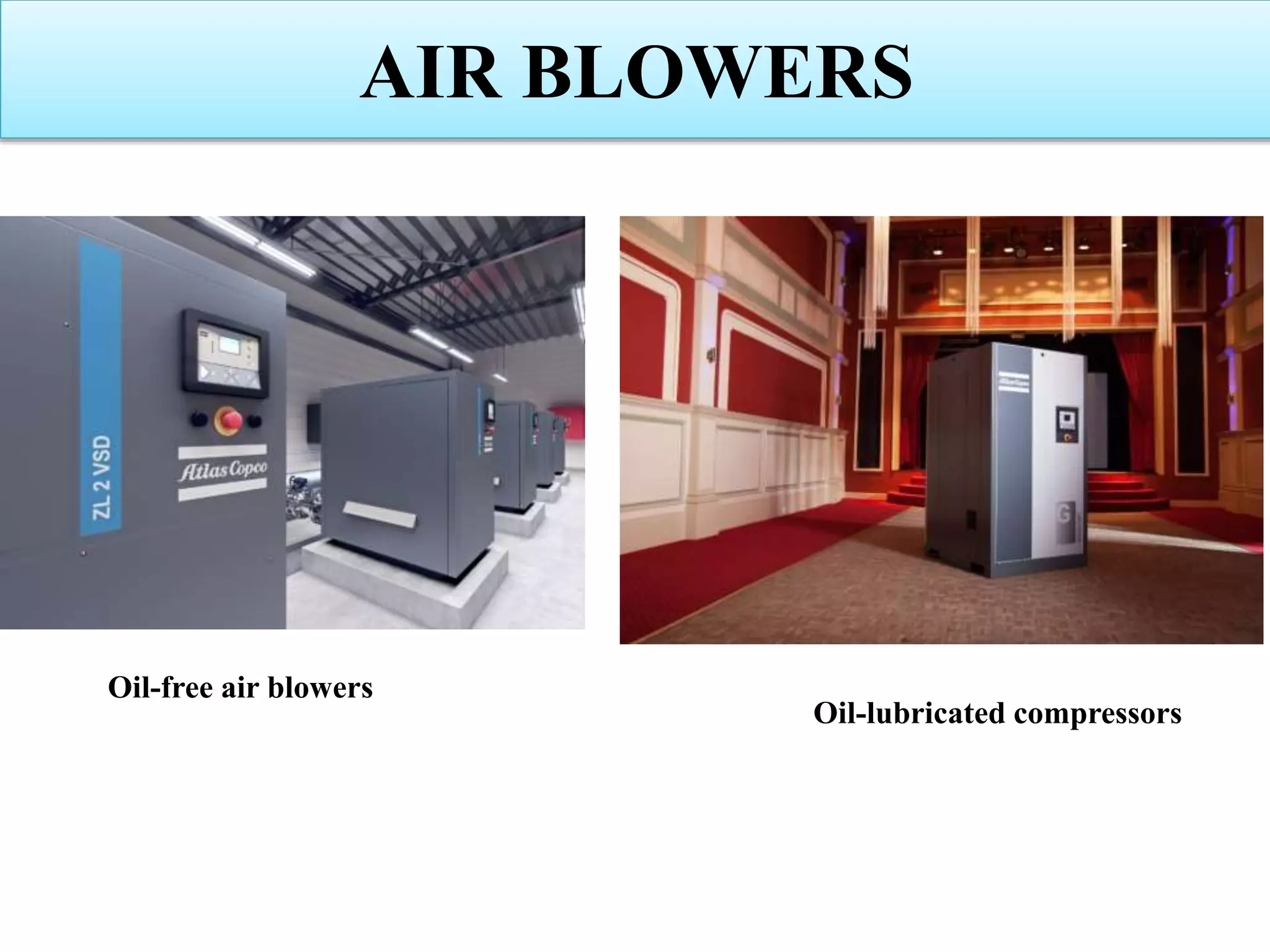
Differentiates between oil-lubricated and non-lubricated compressors, and includes classifications. Focuses on various types of reciprocating compressors as well as rotary screw compressors.
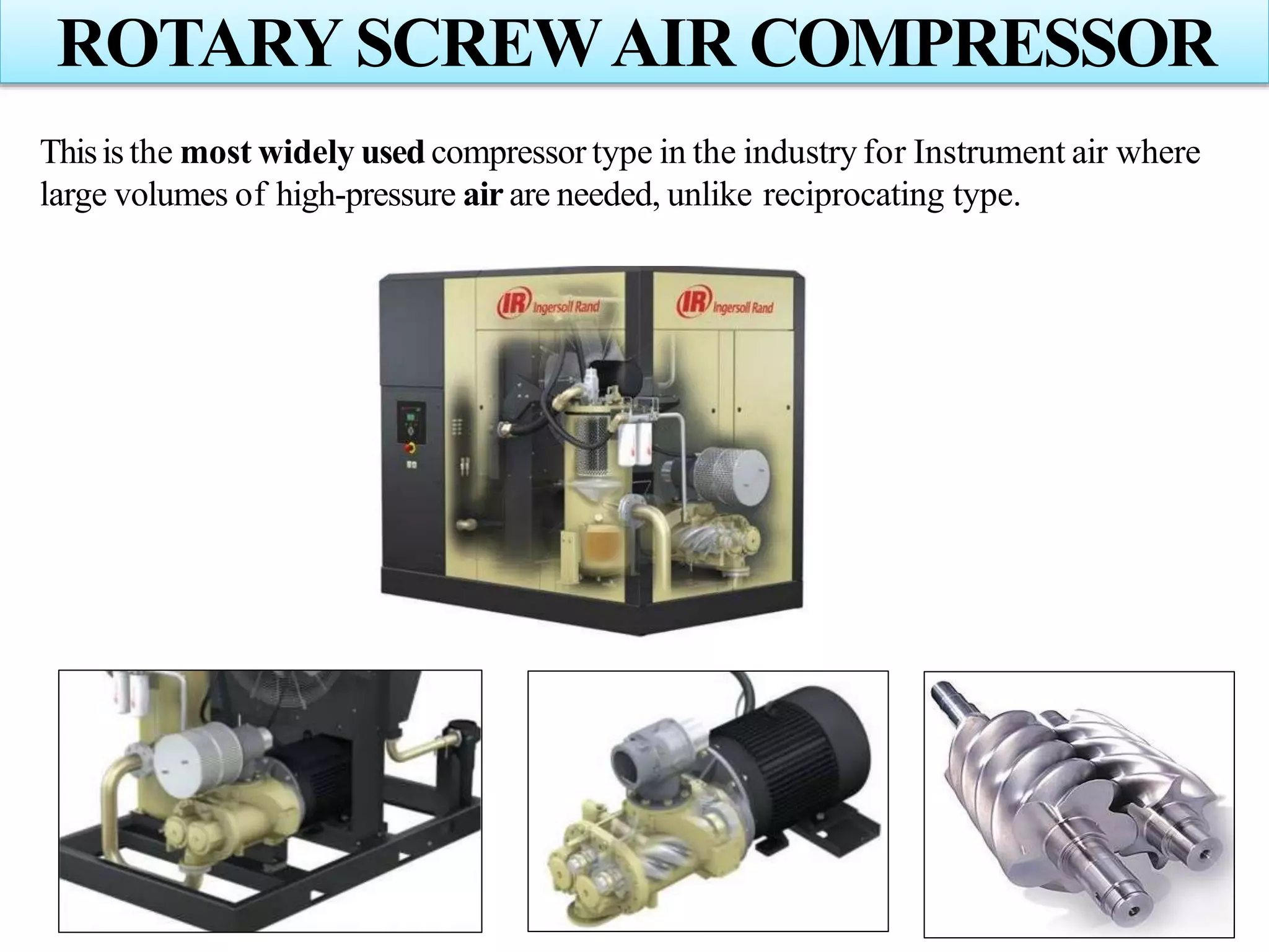
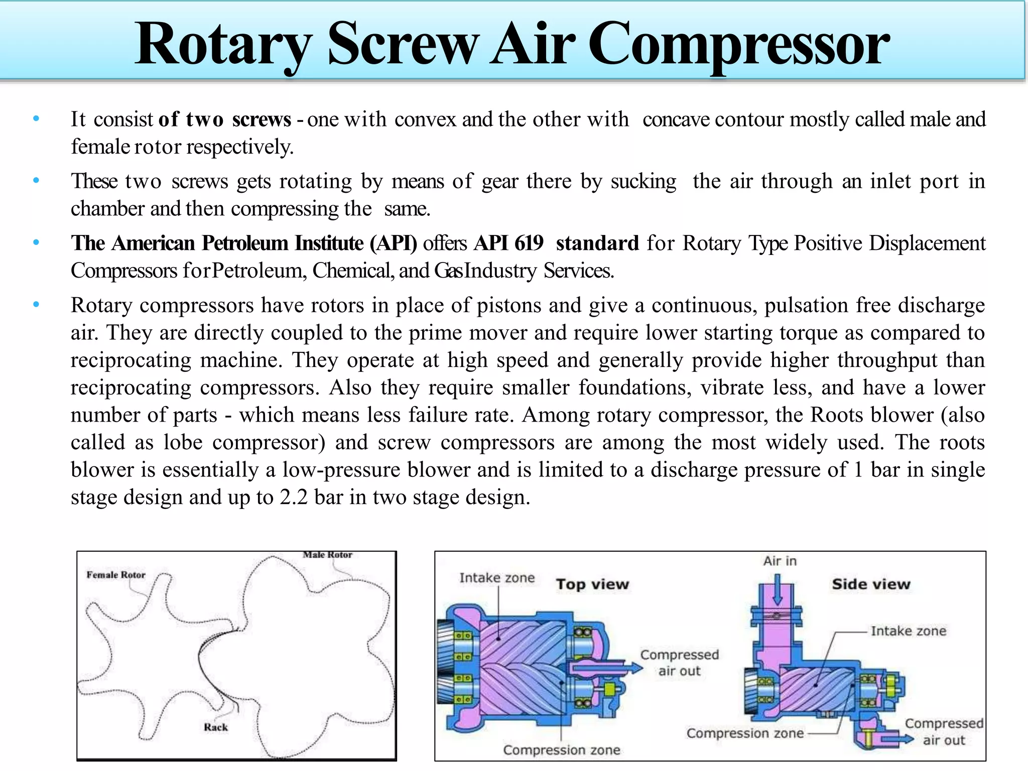
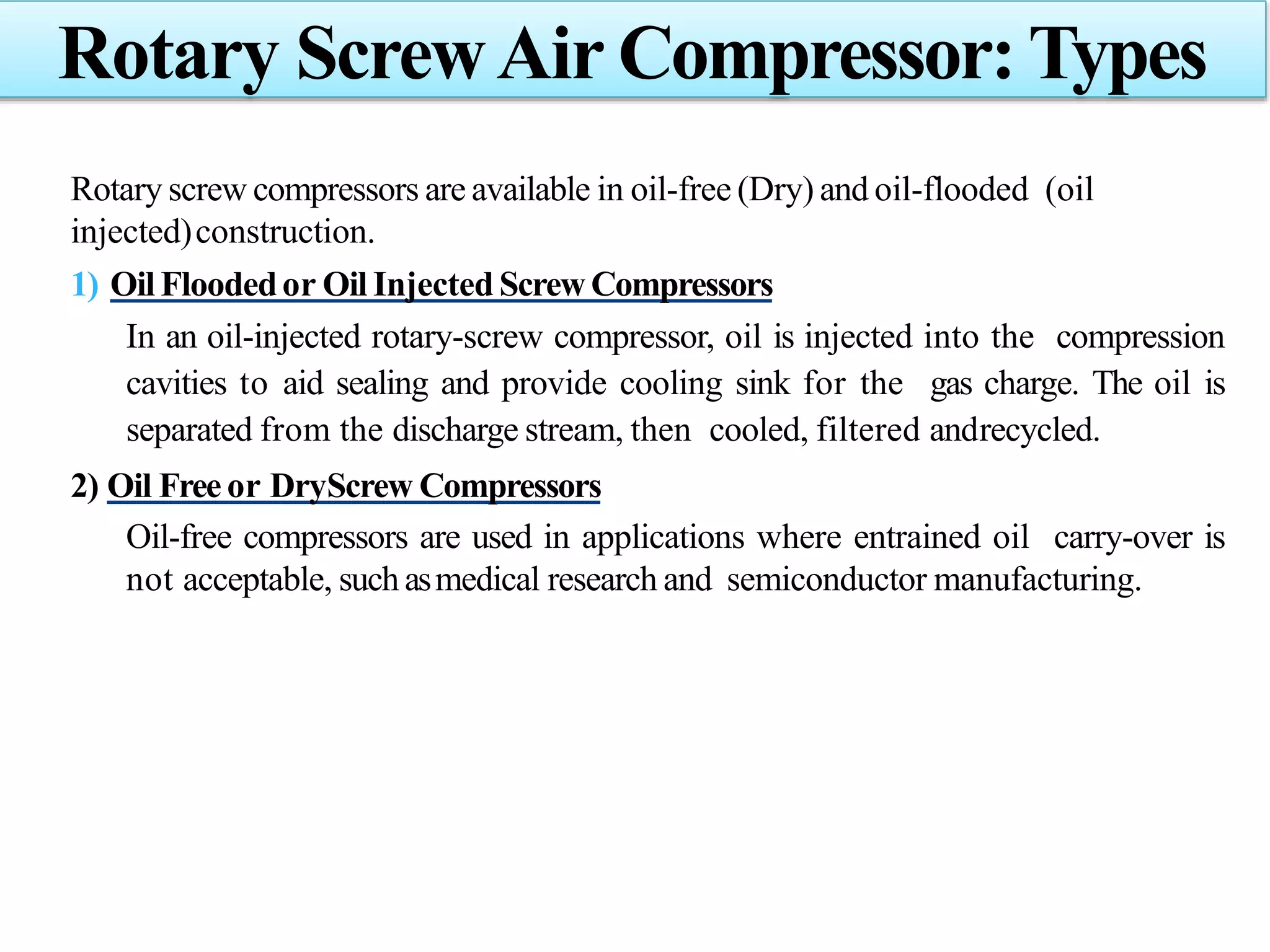
Insights on types and operational principles behind rotary screw air compressors and their applications.
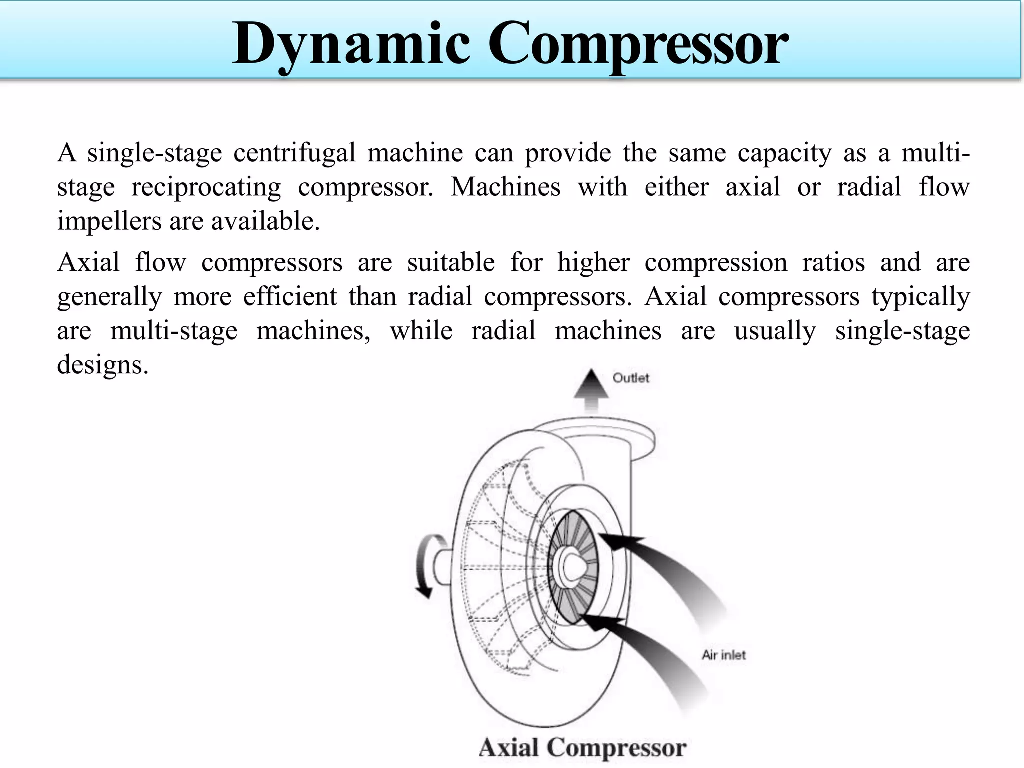
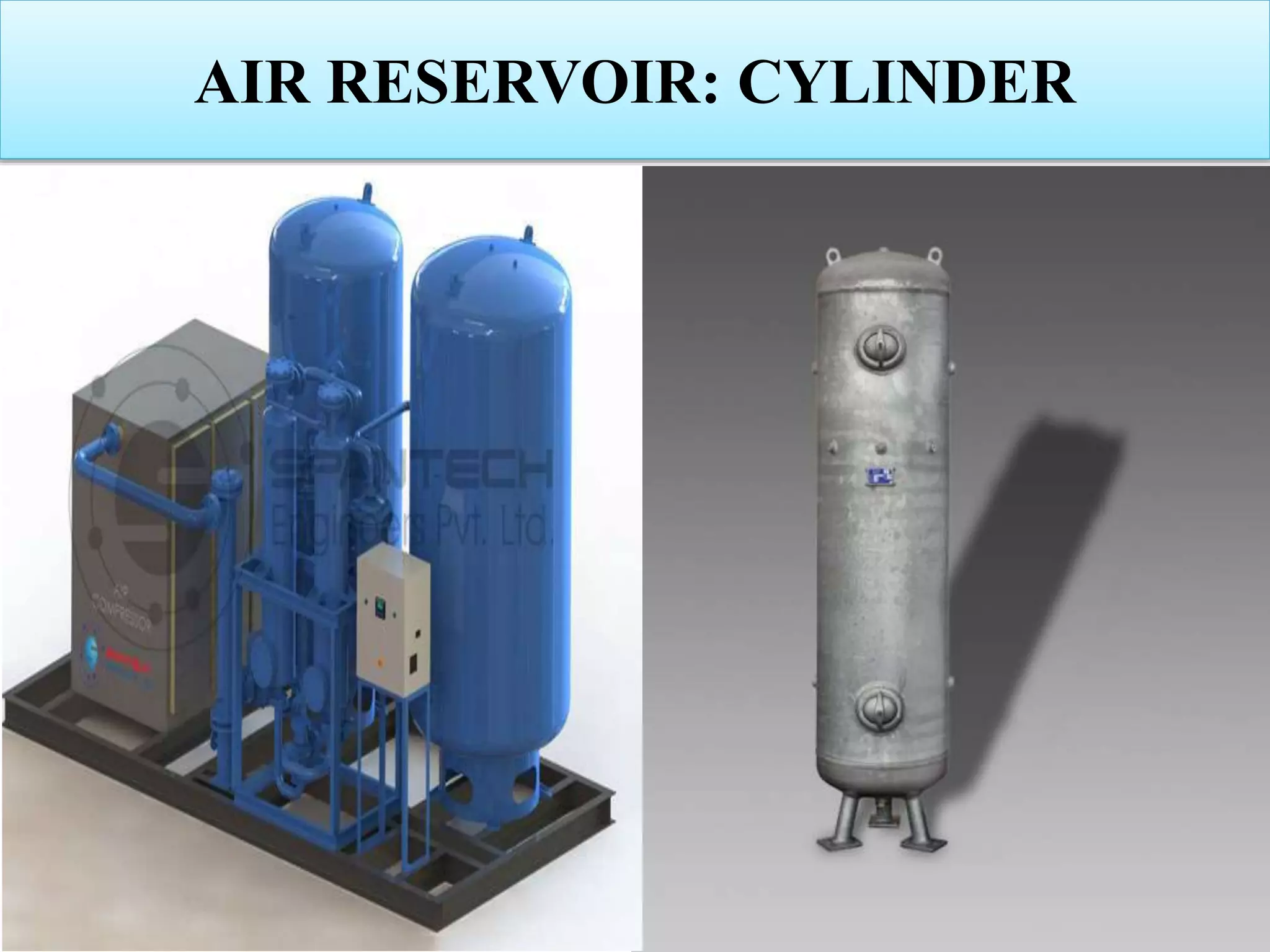
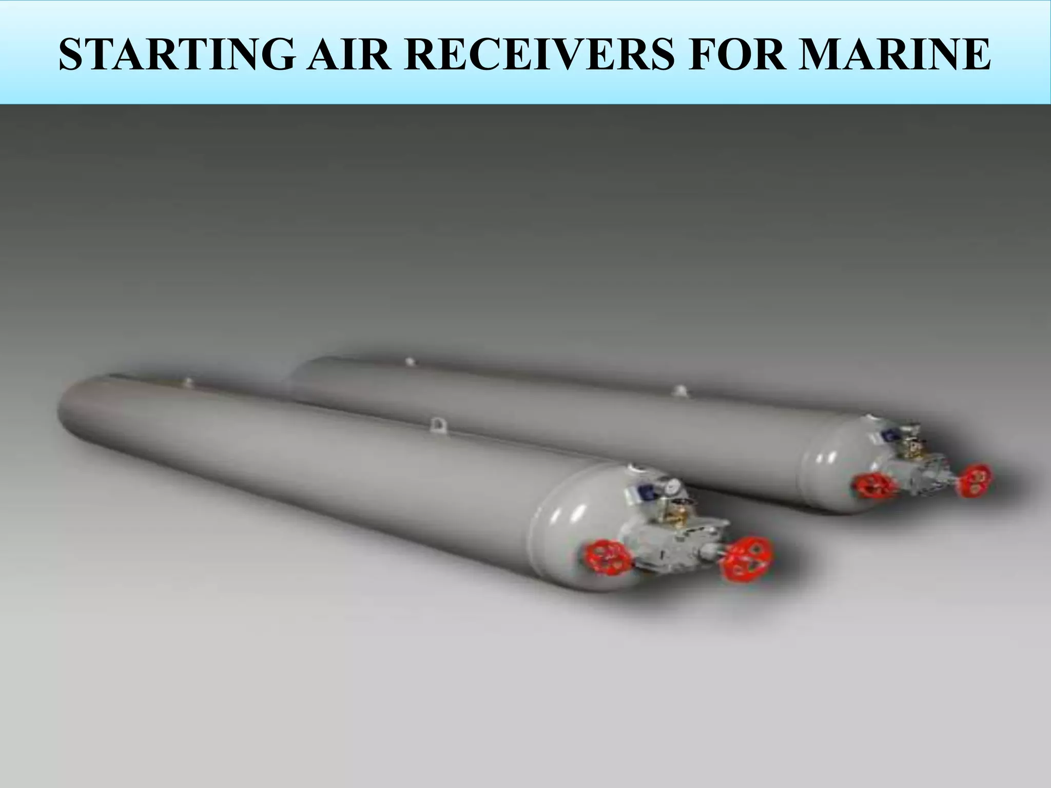
Information on dynamic compressors, including centrifugal and axial flow types for industrial use.Major components critical to the effective functioning of compressed air systems.
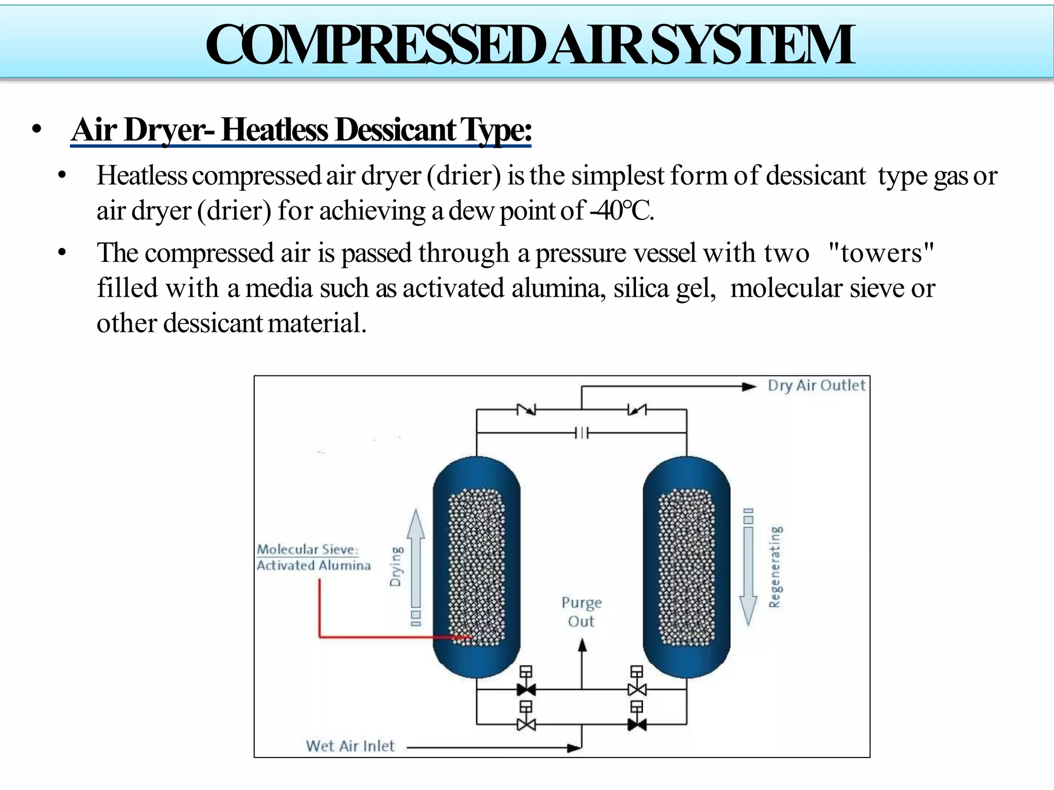
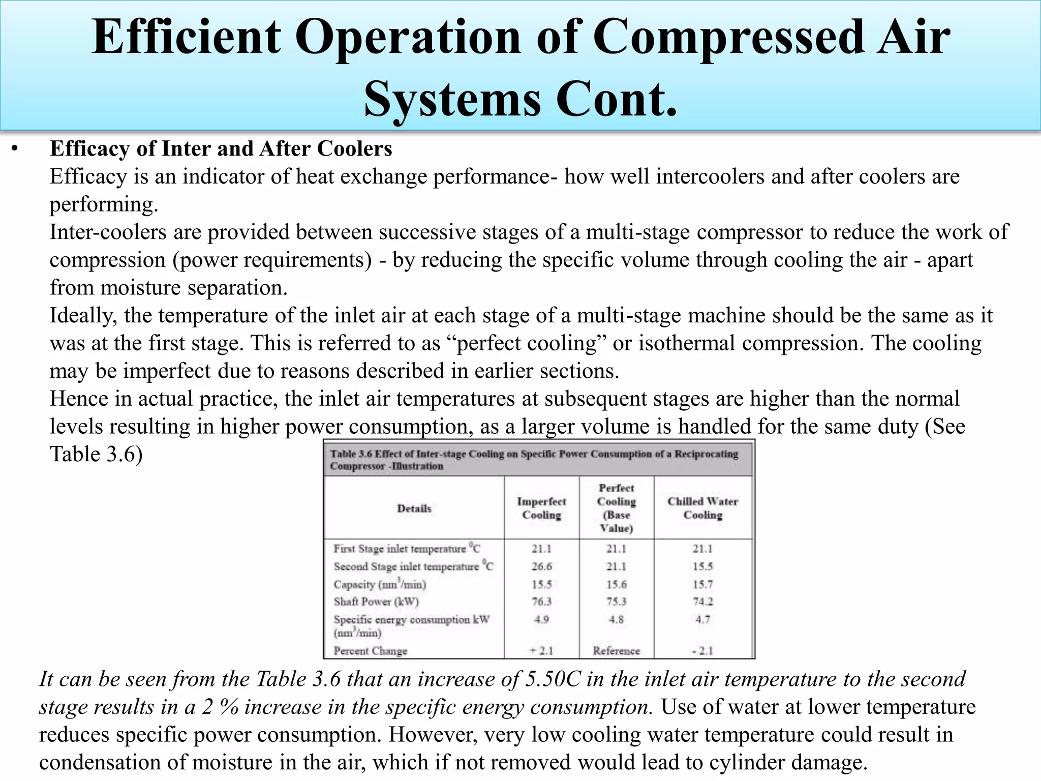
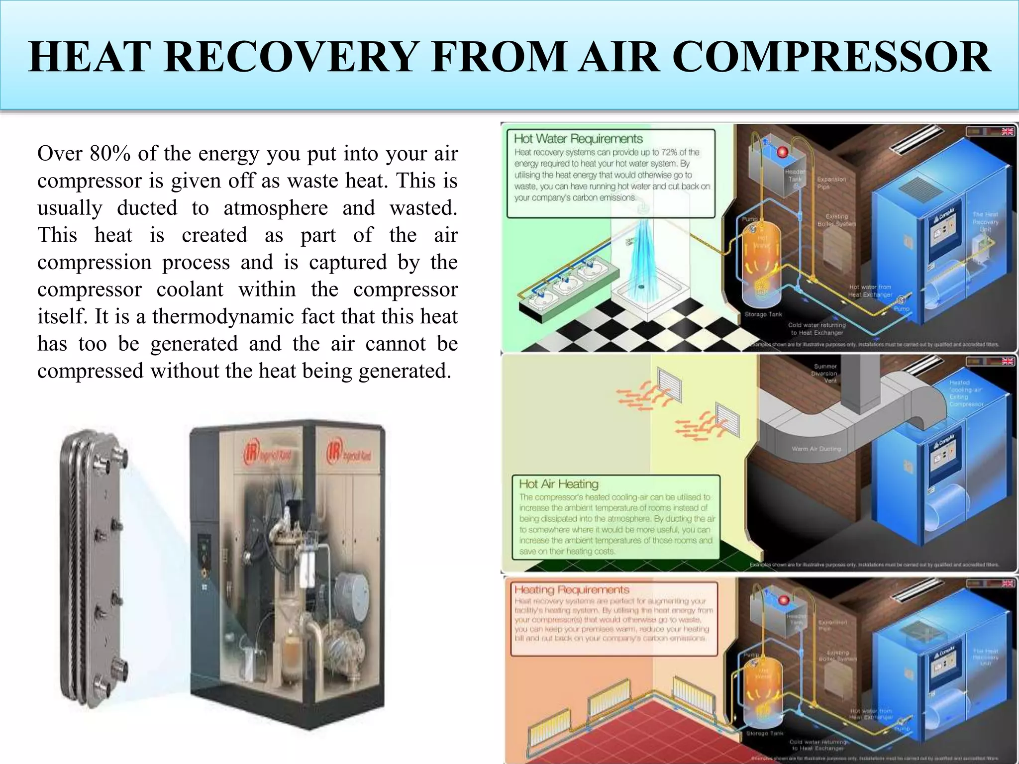
Details on inter and after coolers for moisture removal and temperature management in compressors.
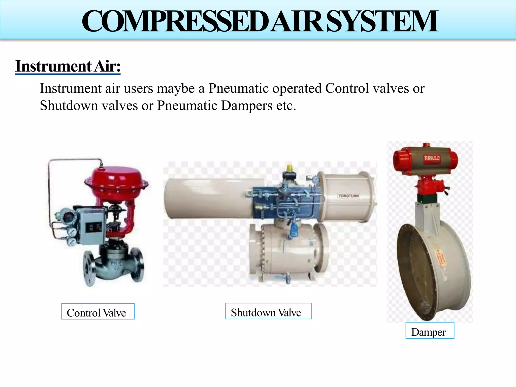
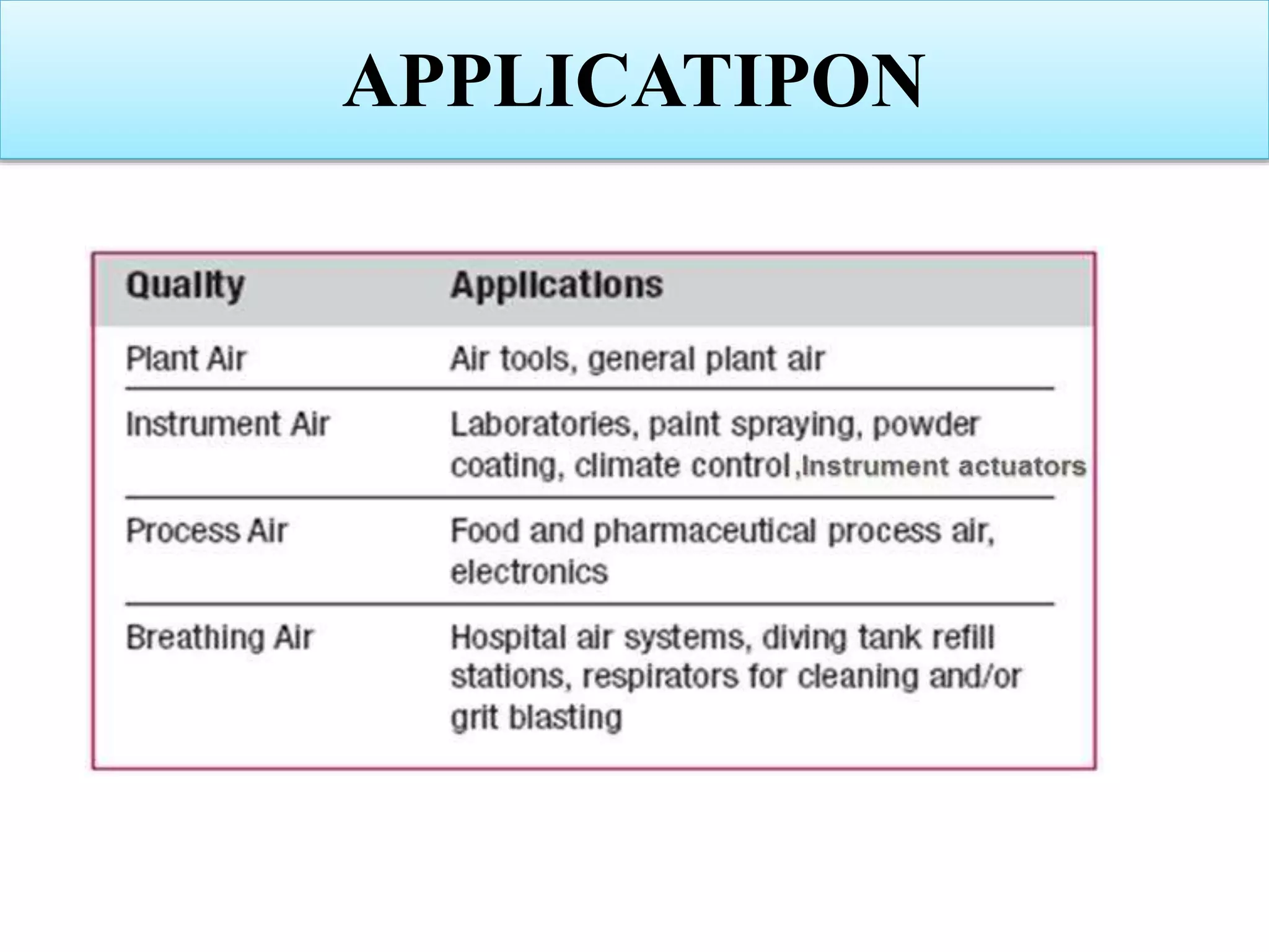
Describes the necessity for instrument air systems in maintaining operation in pneumatic instruments.Factors affecting air quality and parameters needed for ensuring high-quality instrument air.
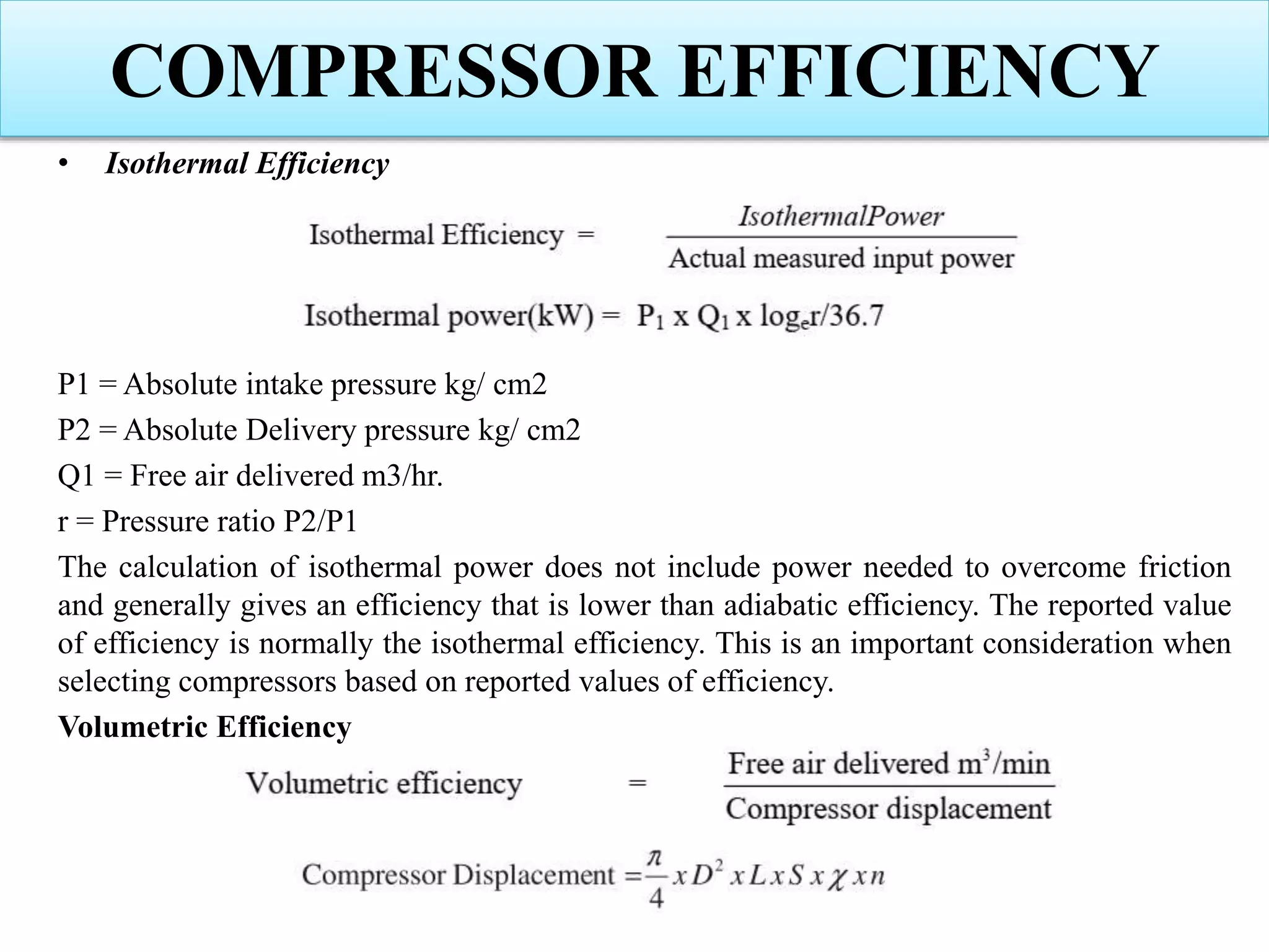
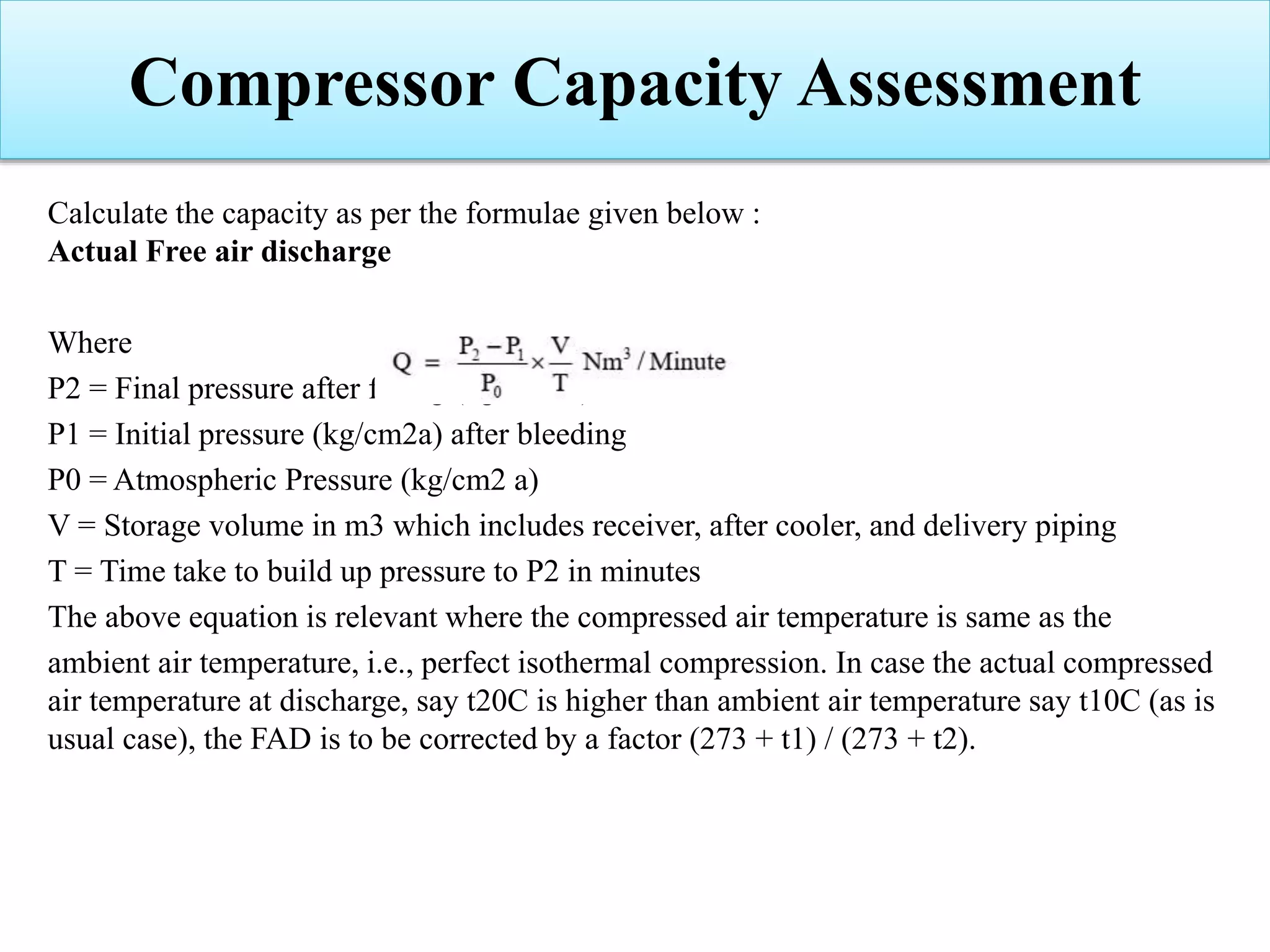
Discussion on compressor capacity, performance metrics, and various efficiency measures.
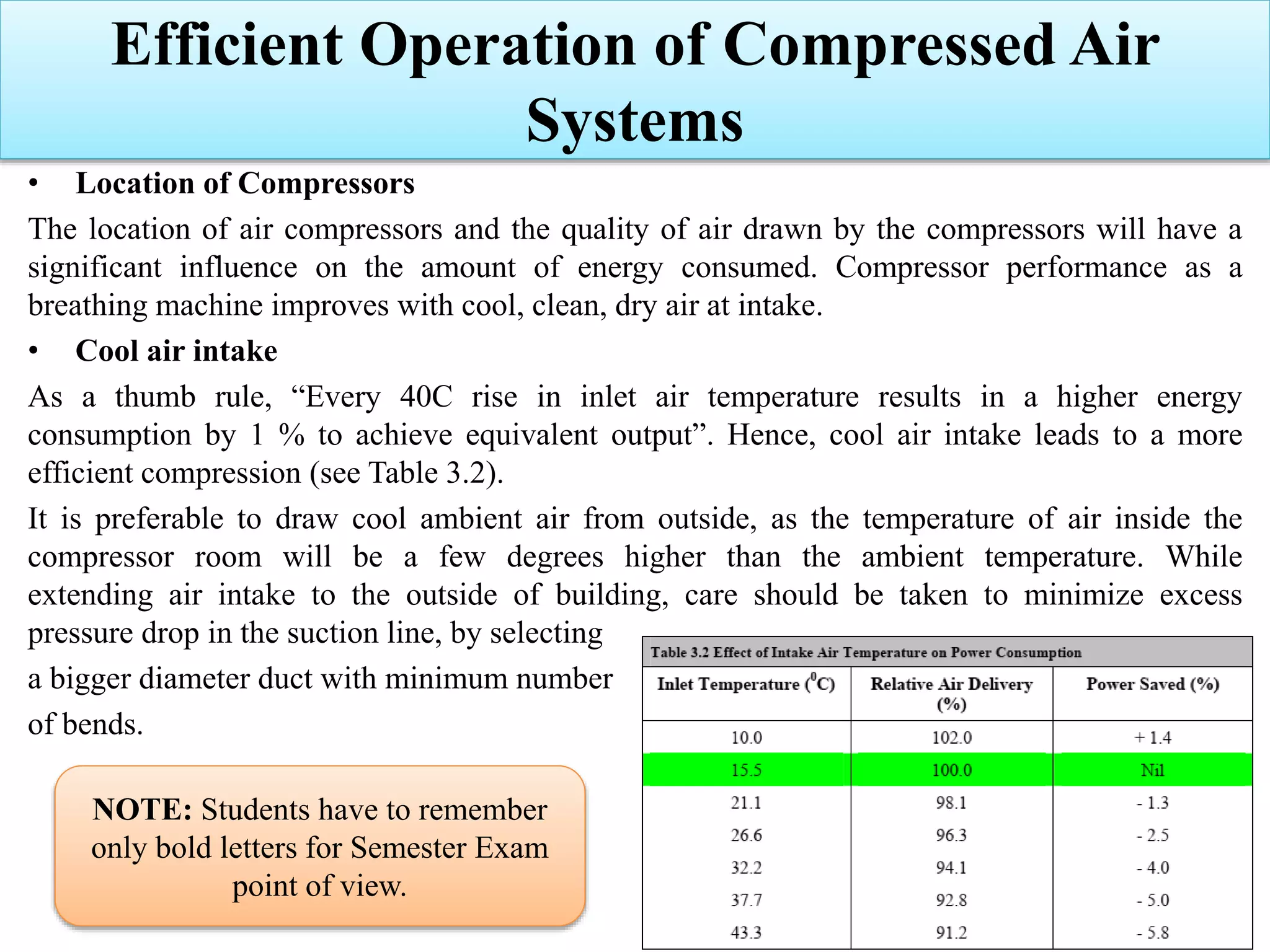
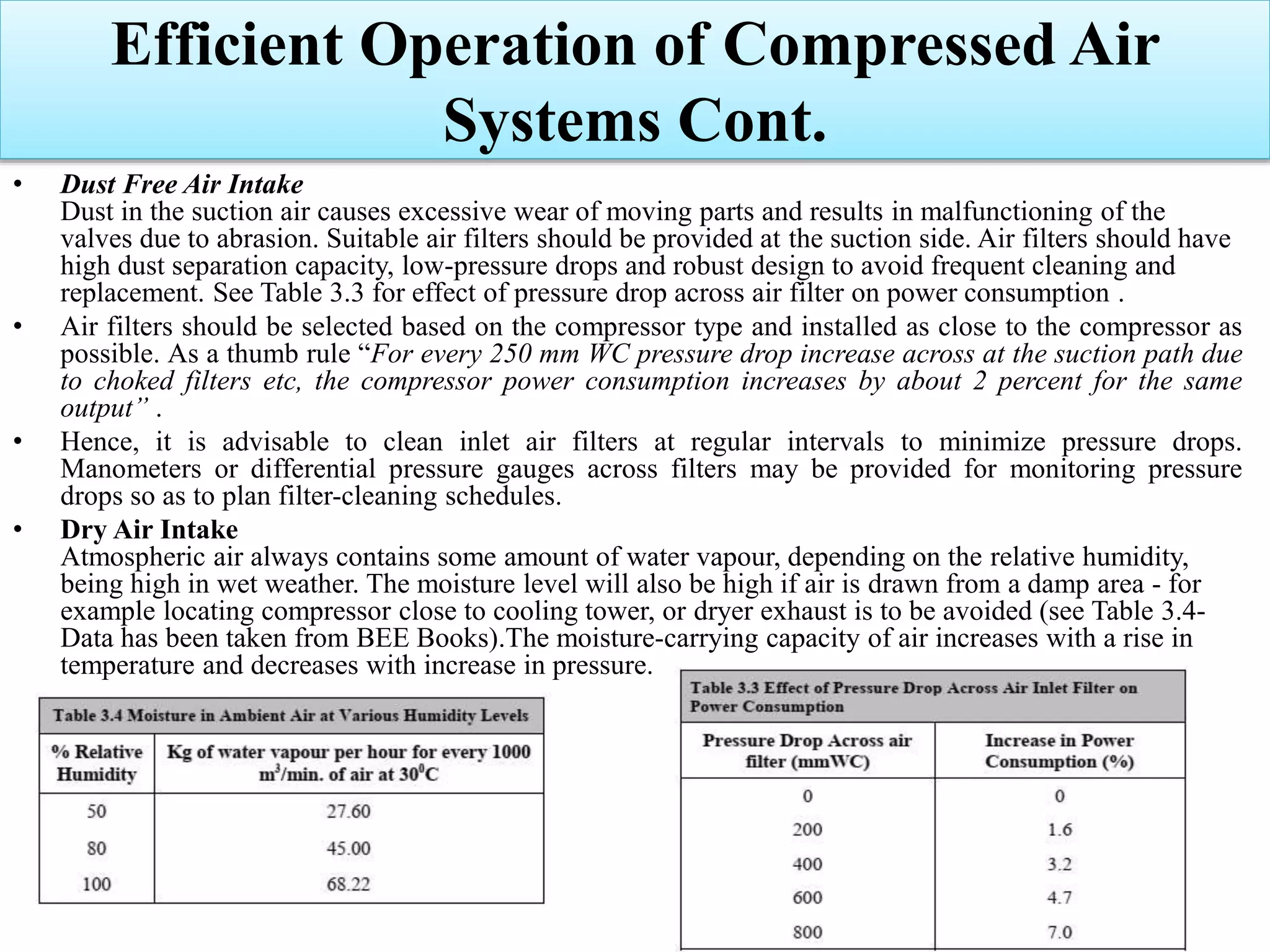
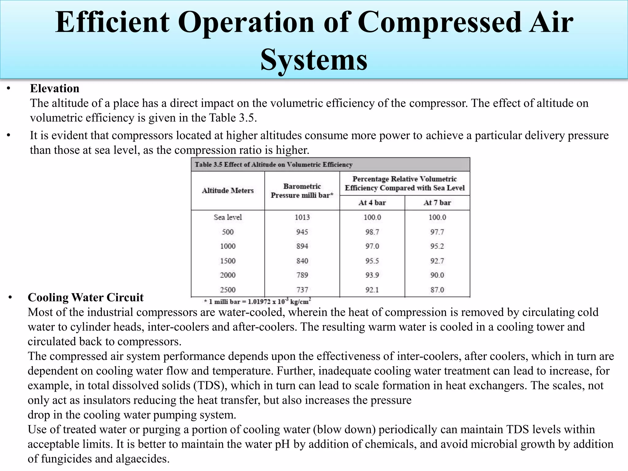
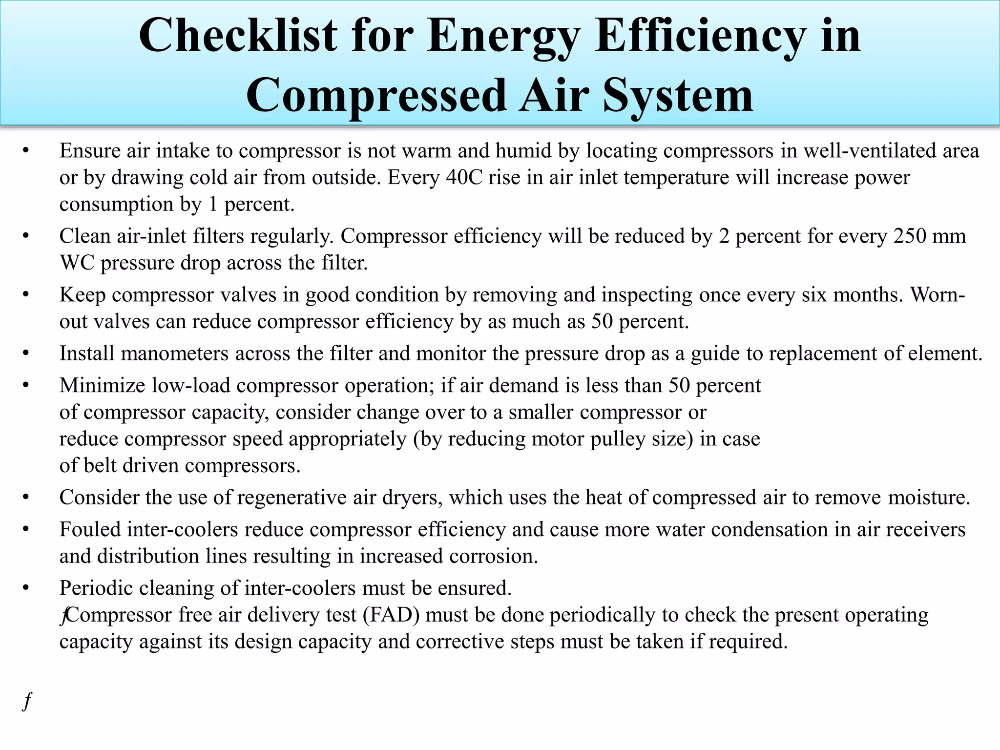
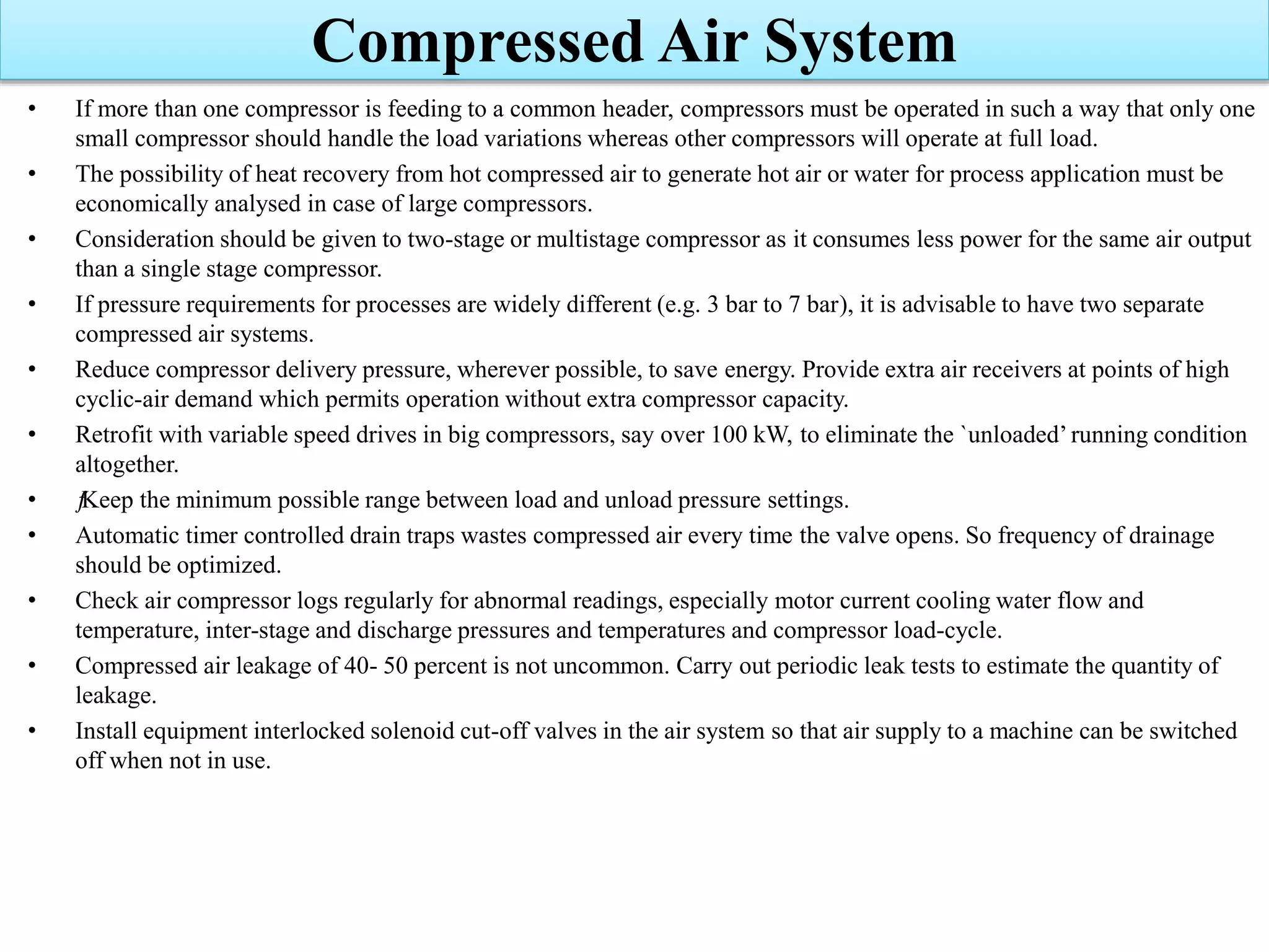
Strategies for improving operational efficiency and performance across compressed air systems.
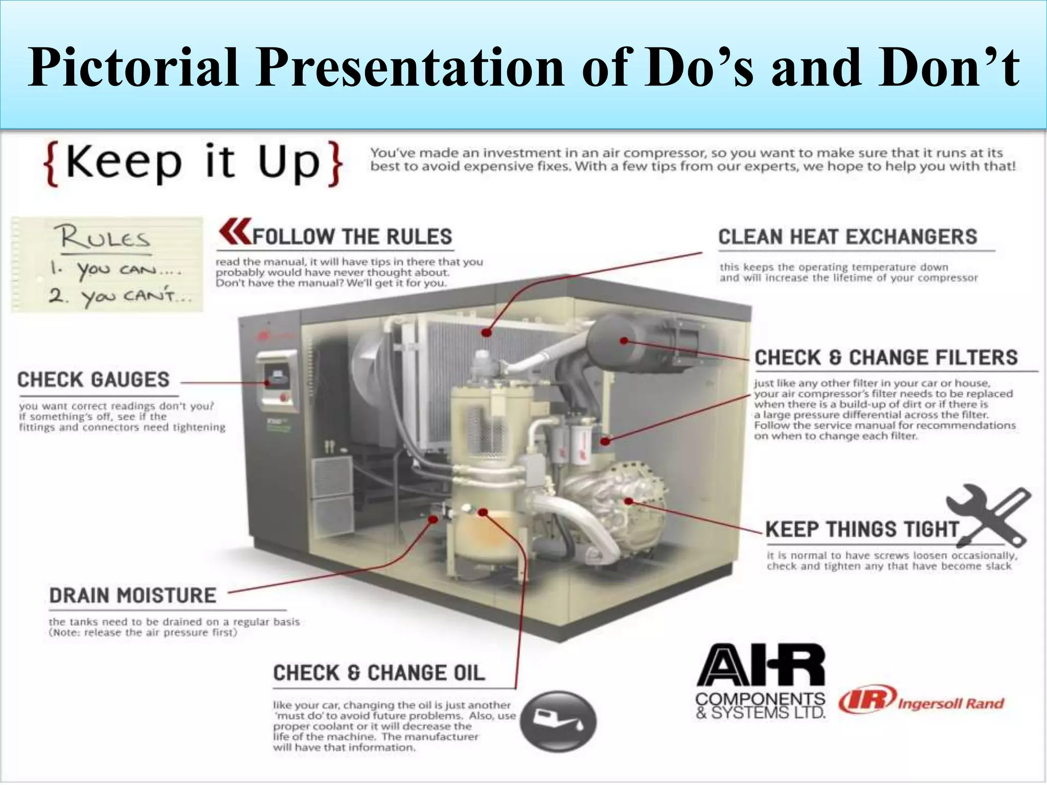
Best practices for maintaining compressors, ensuring FAD and operational performance.
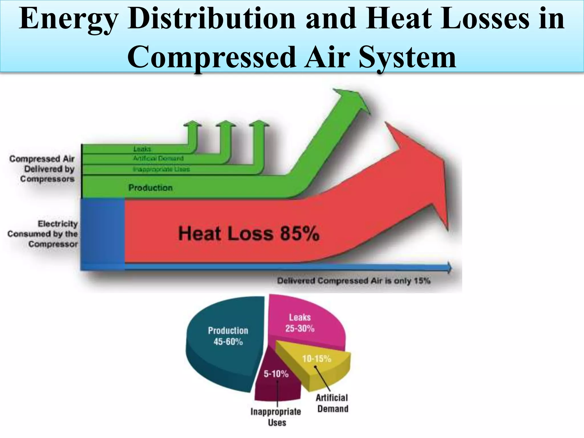
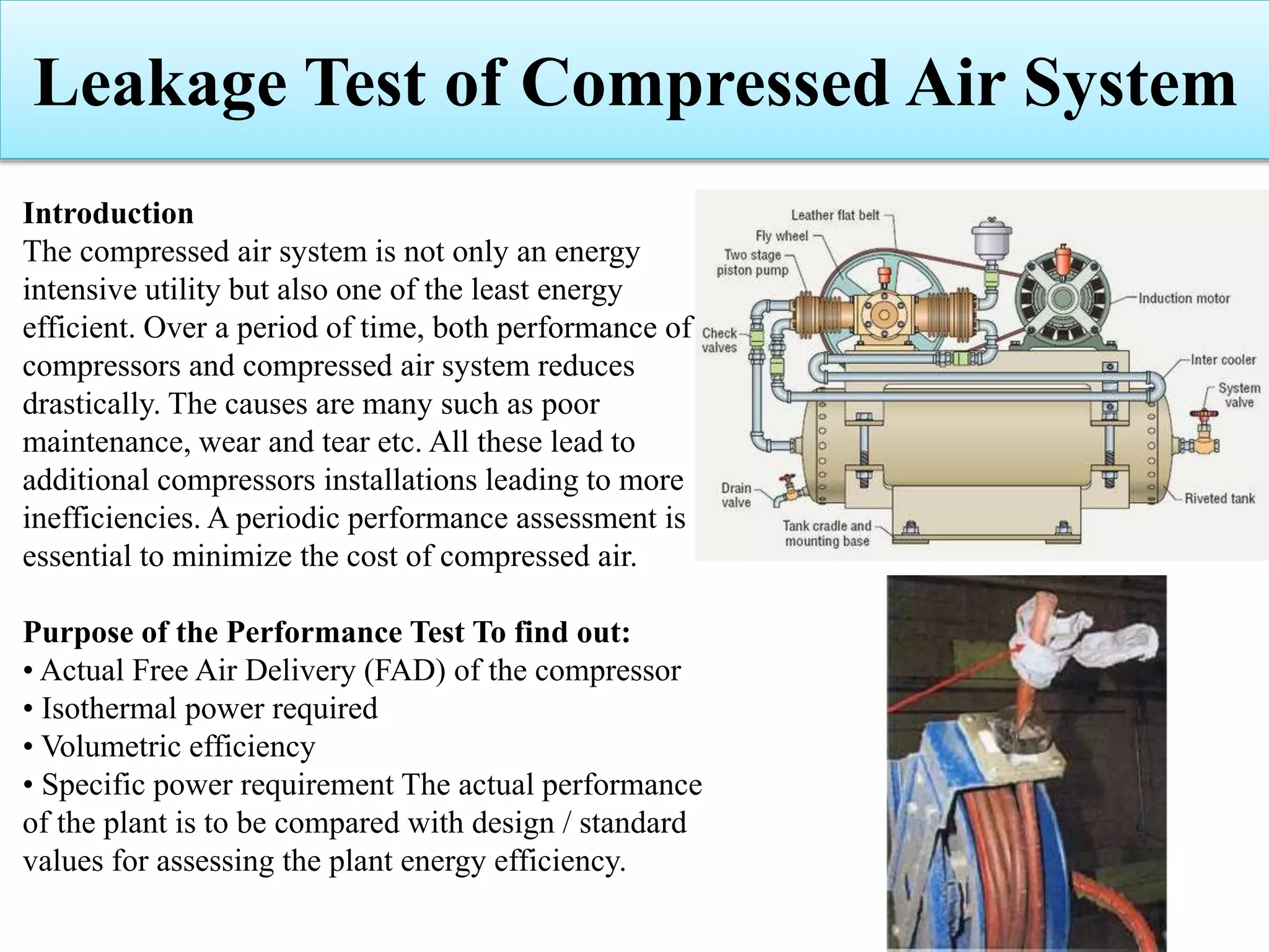
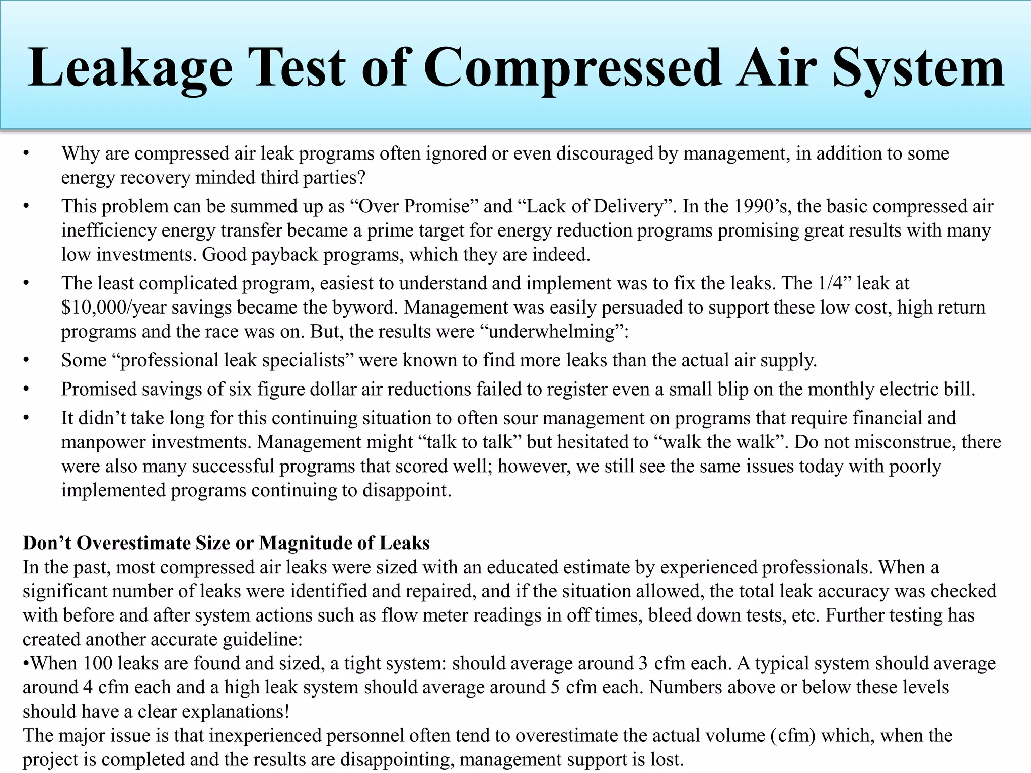
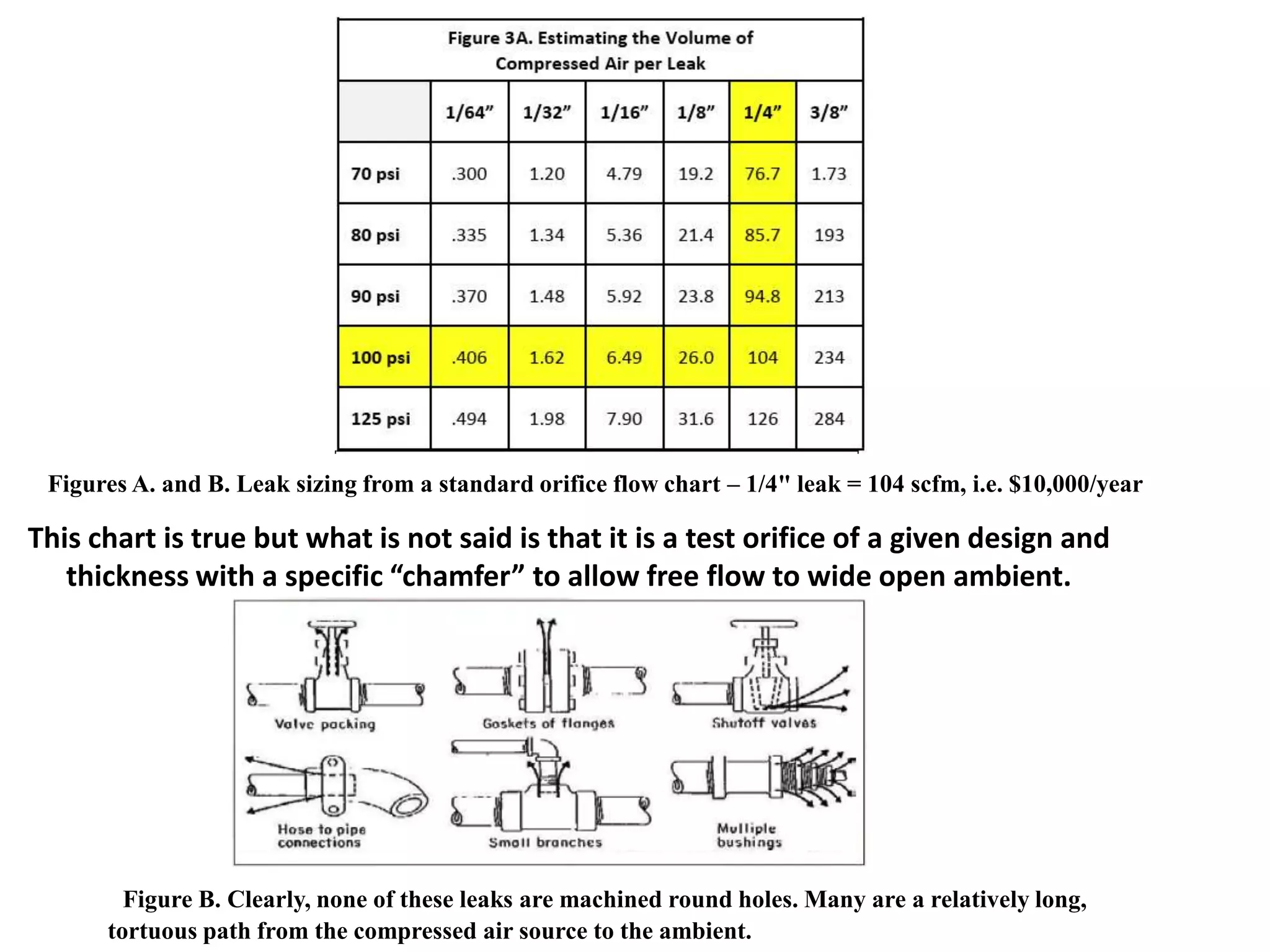
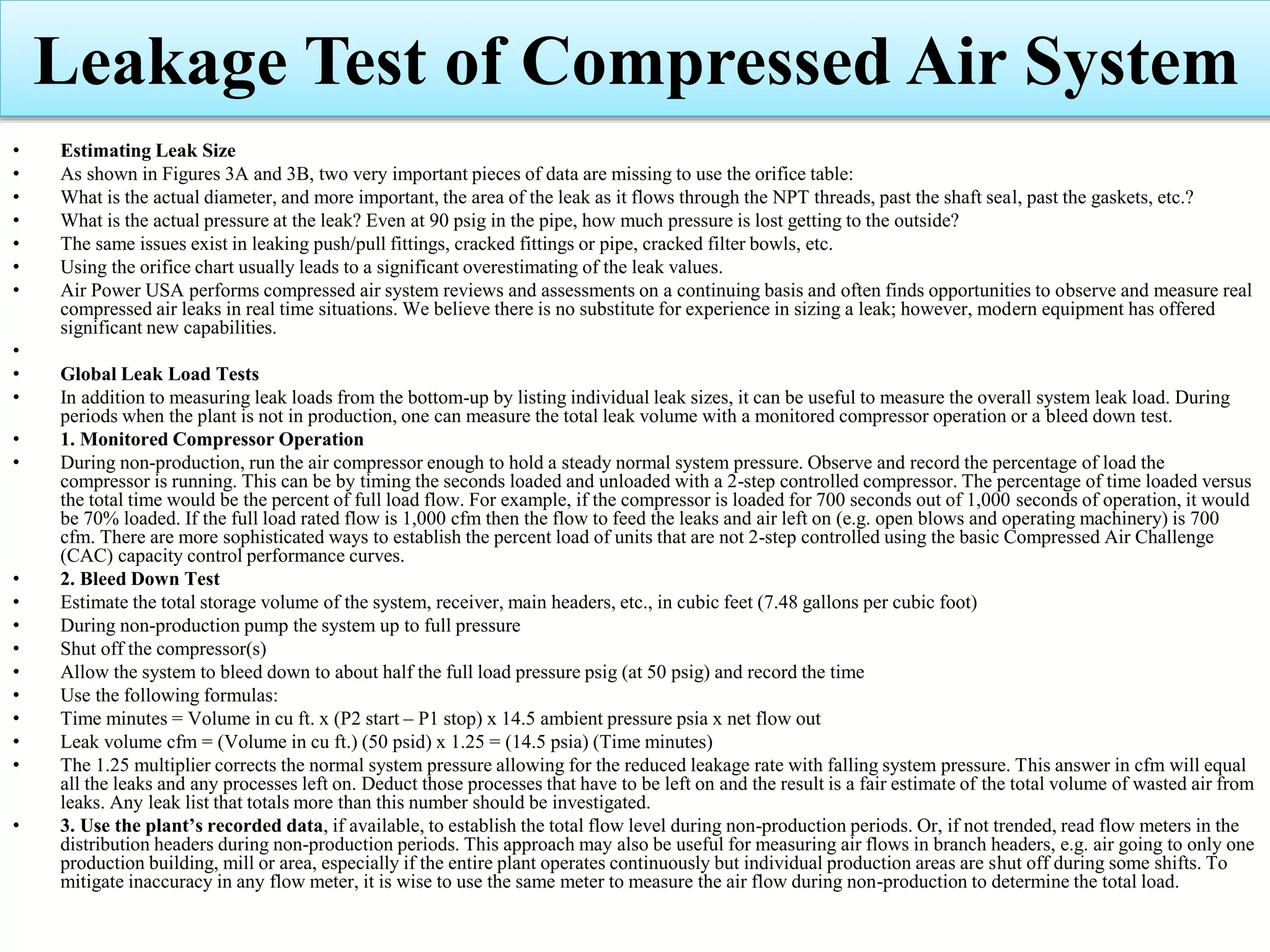
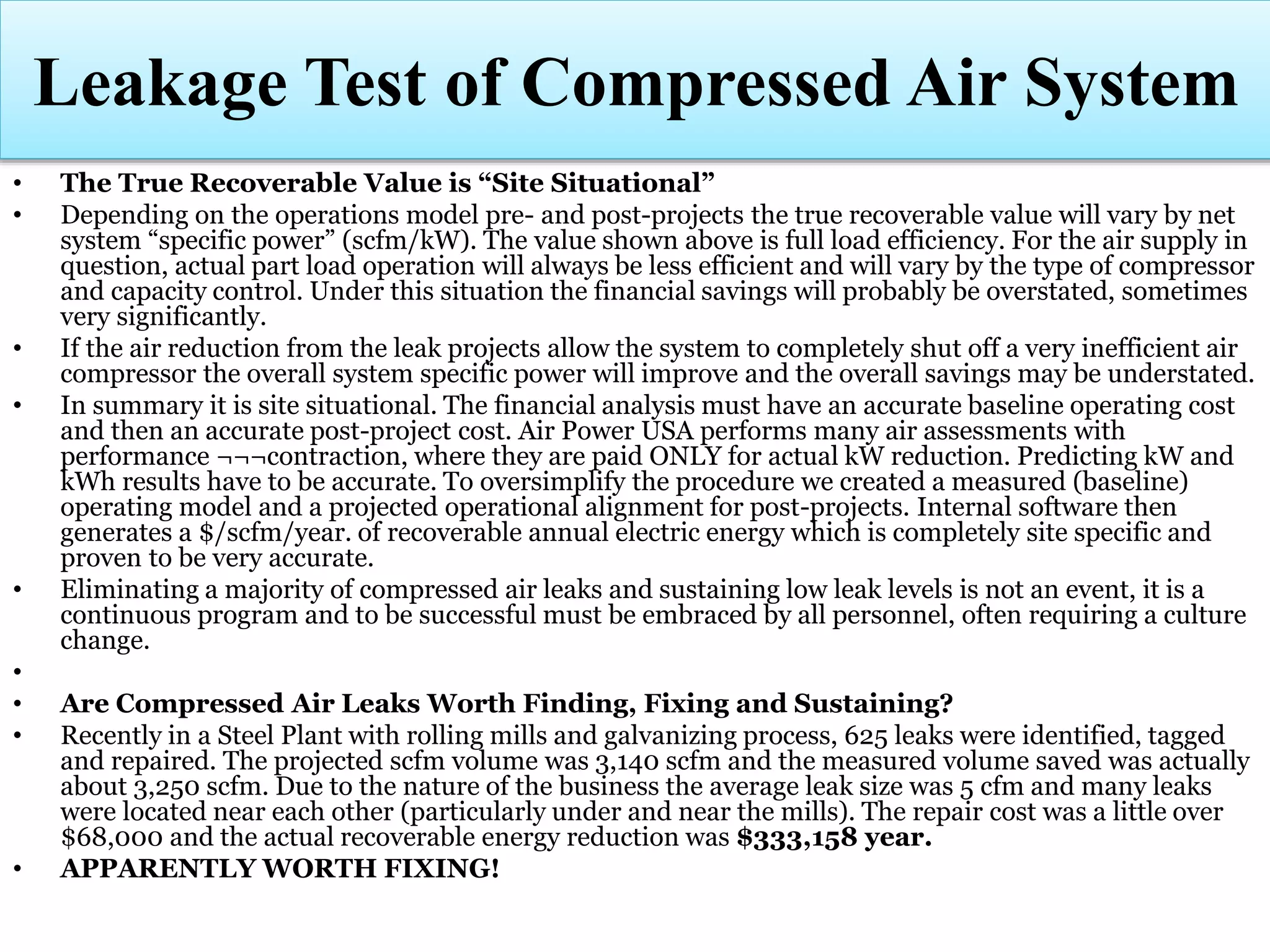
Approaches for assessing leakage in compressed air systems and their effects on efficiency.
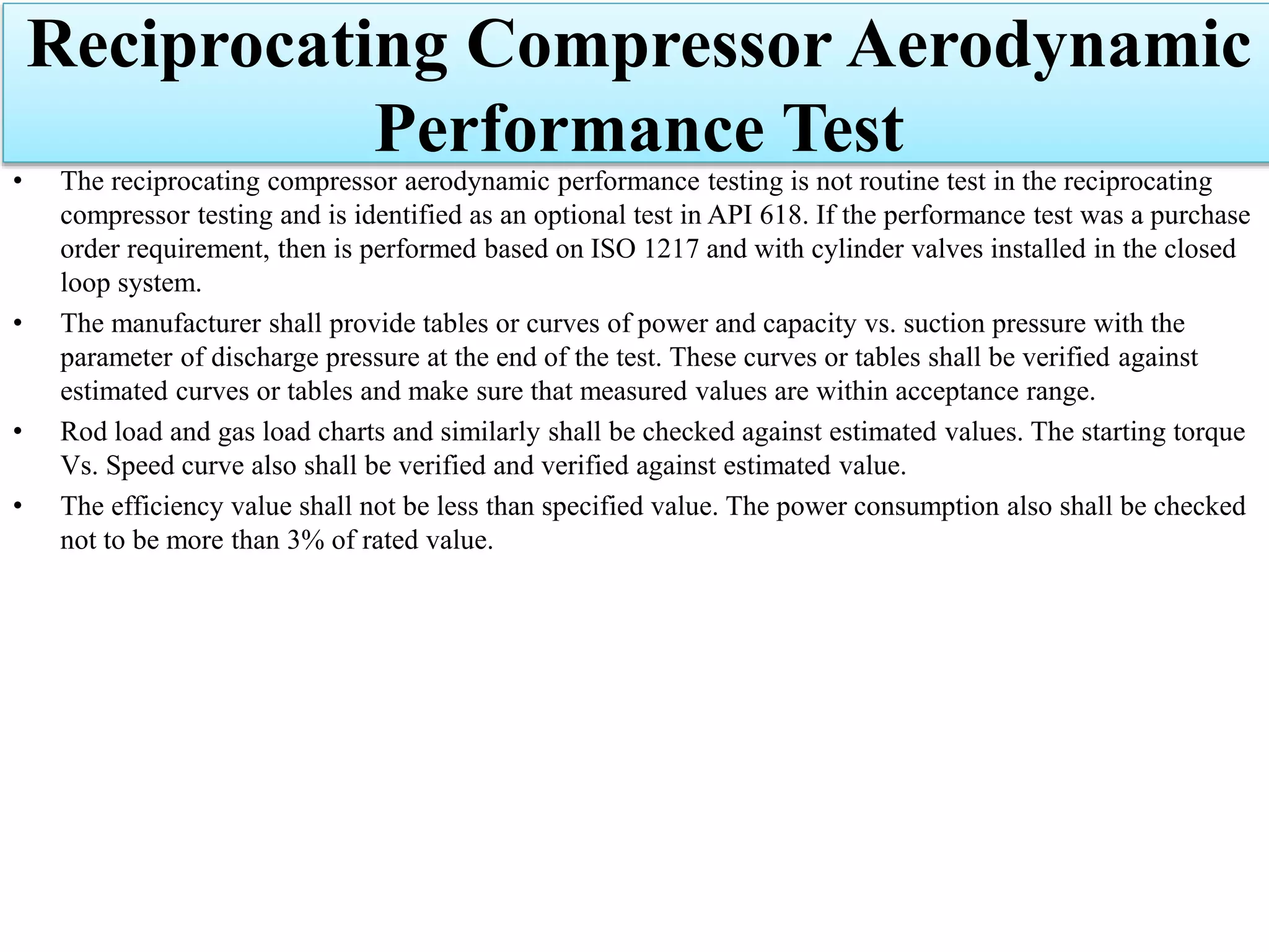
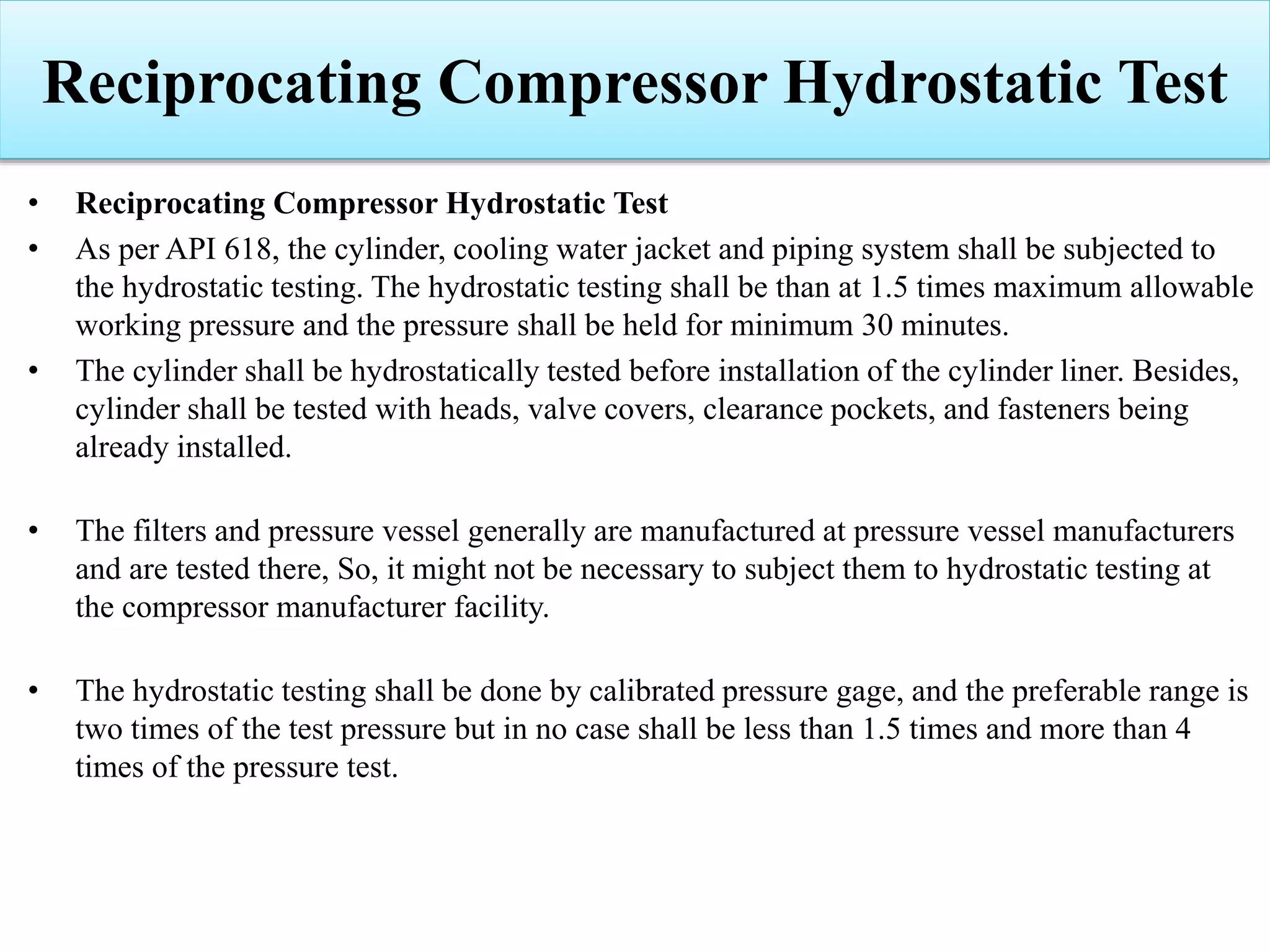
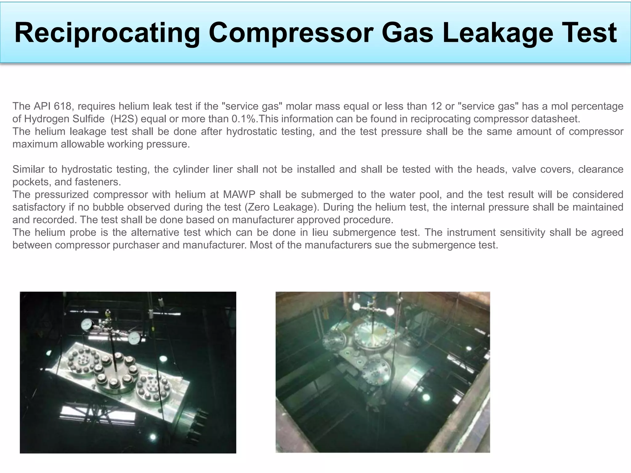
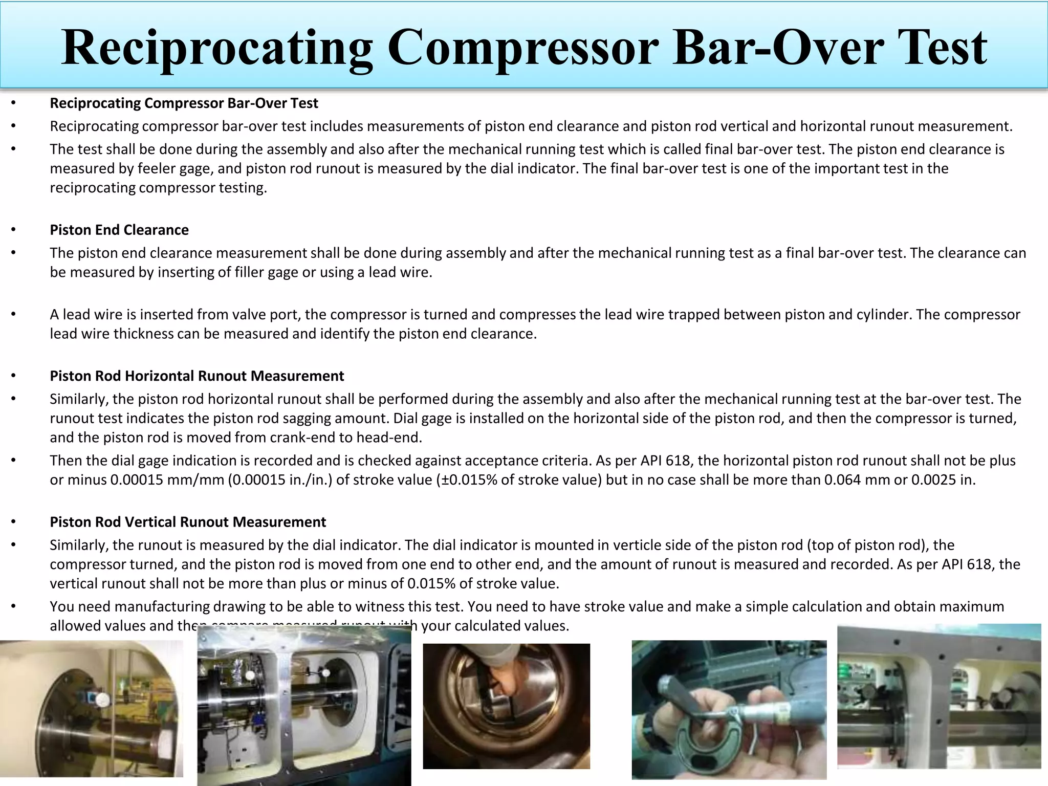
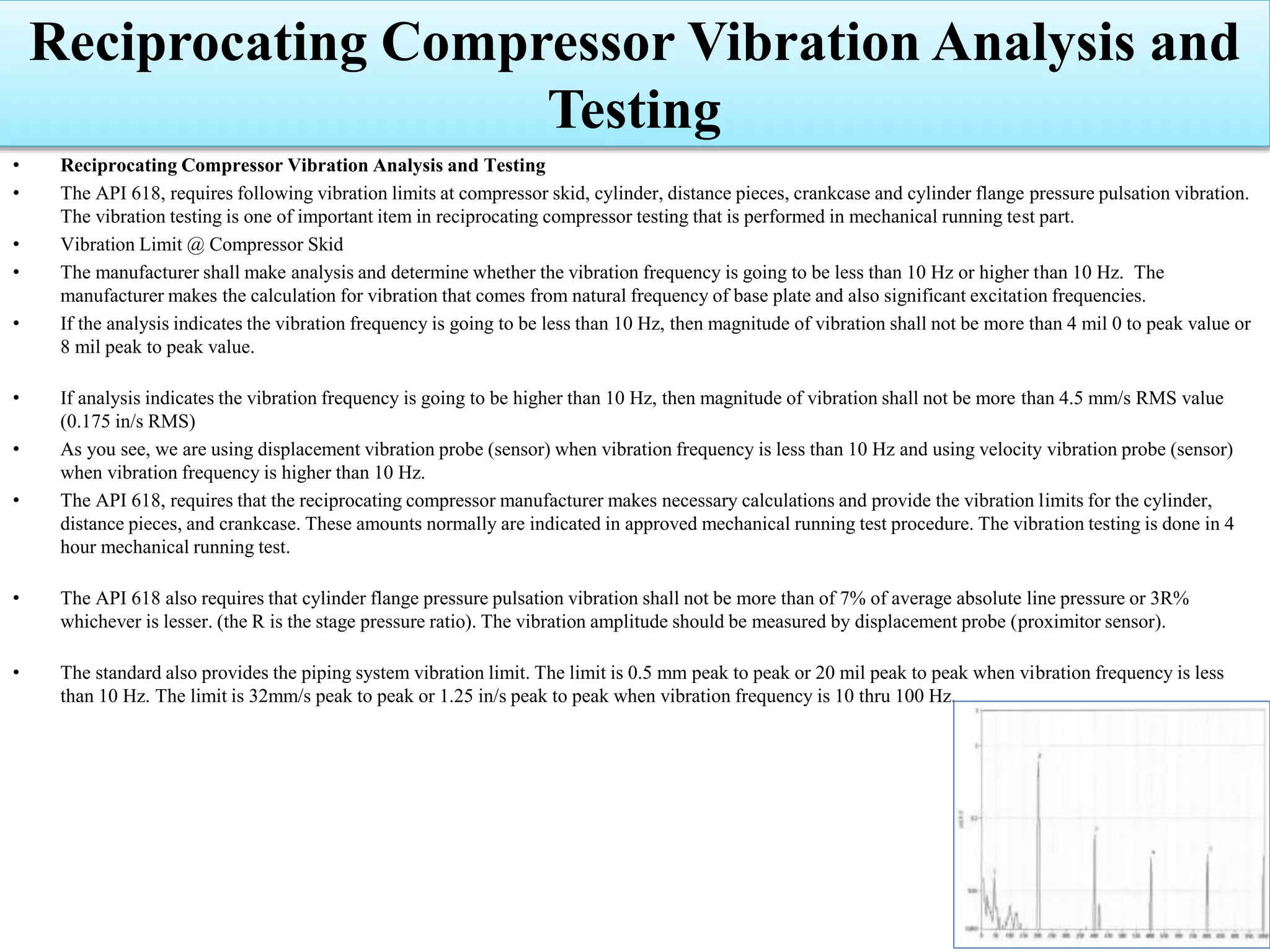
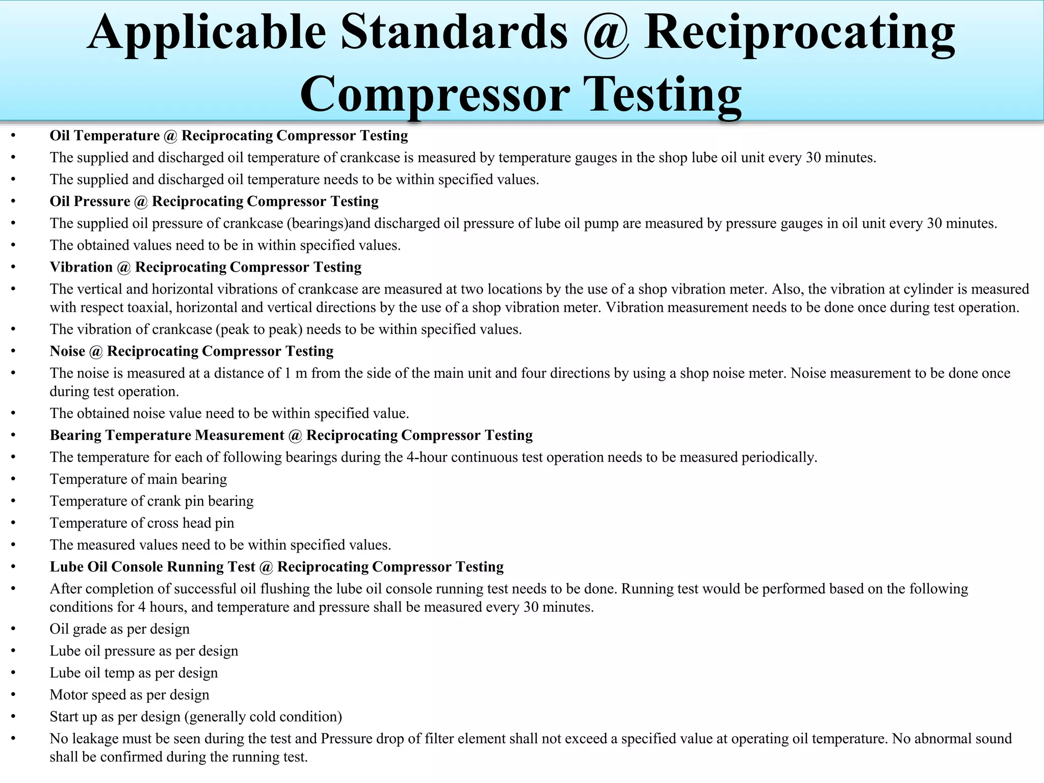
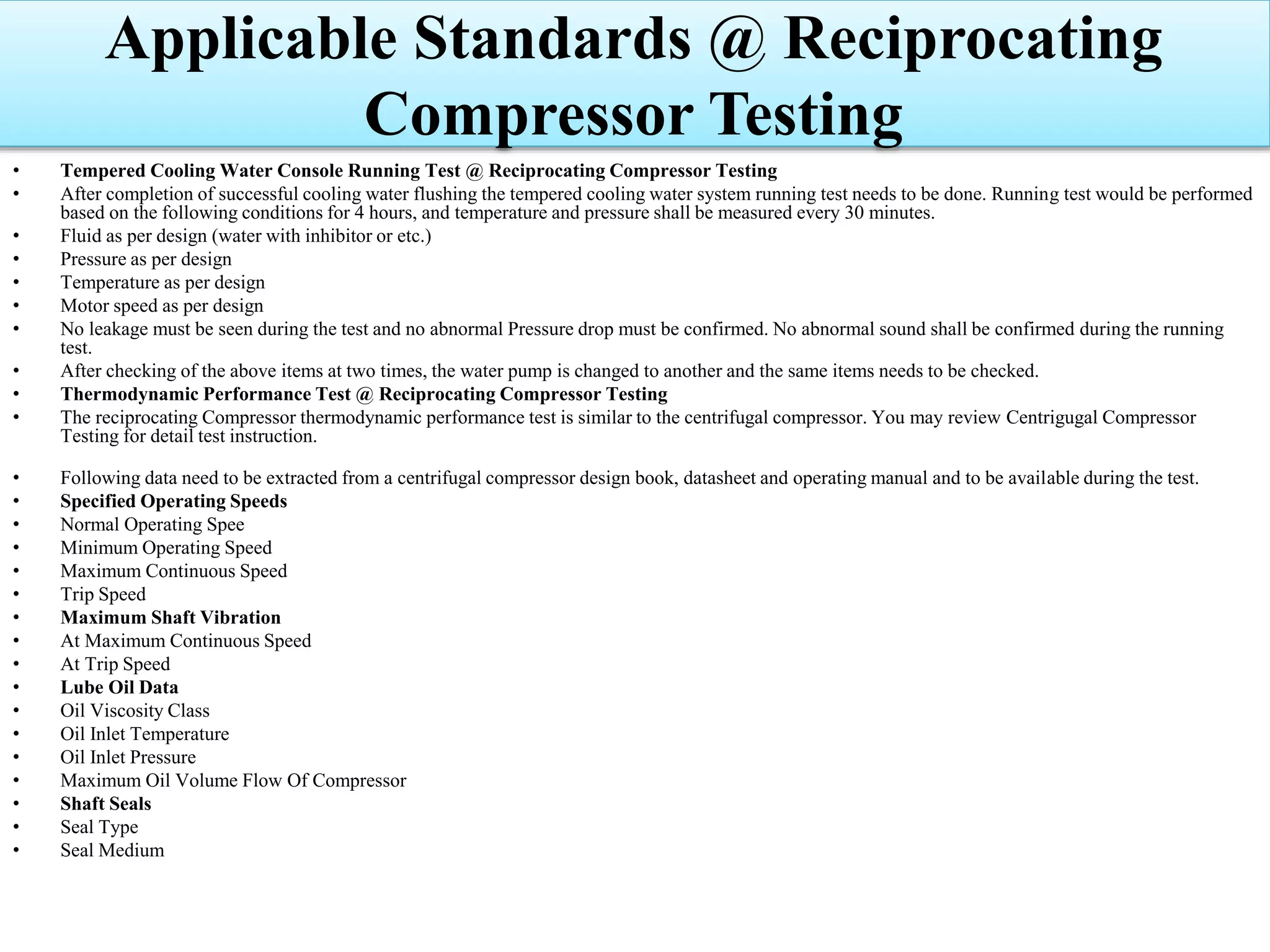
Detailed mechanical, vibration, and hydrostatic tests based on API 618 standards.
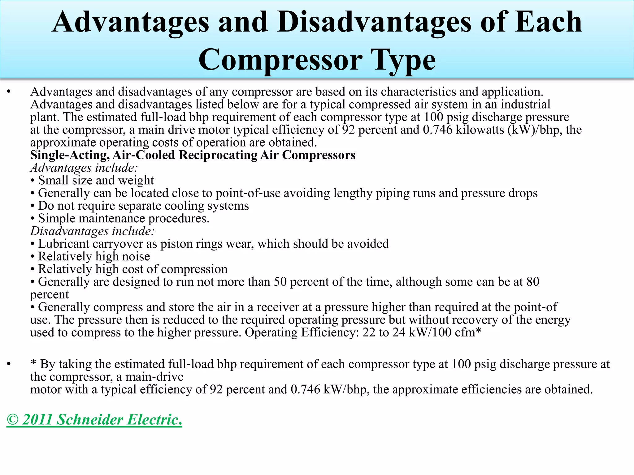
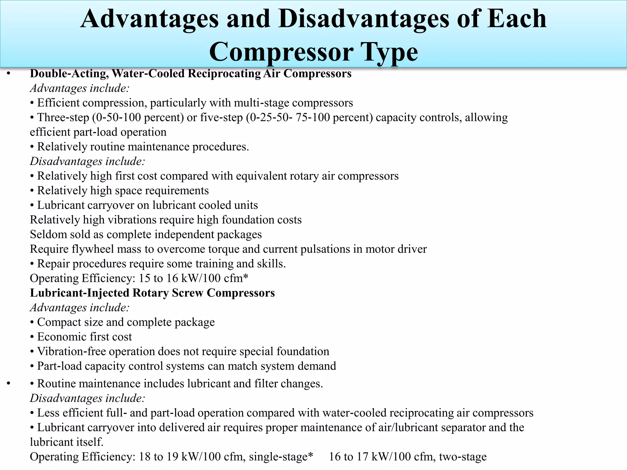
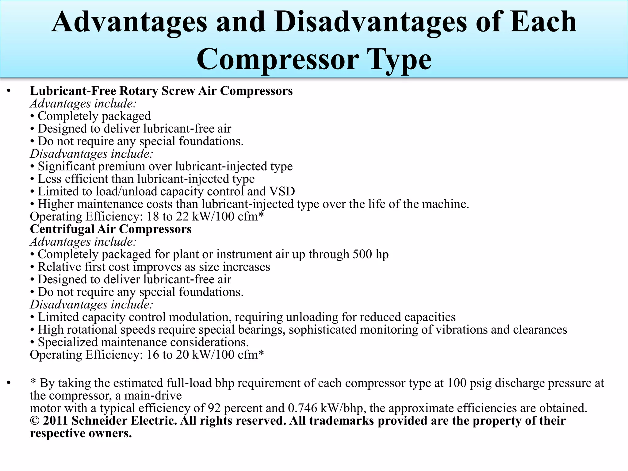
Evaluation of advantages and disadvantages of various compressor types, emphasizing efficiency.


![SBP- Air compressor [Compatibility Mode].pdf](https://cdn.slidesharecdn.com/ss_thumbnails/sbp-aircompressorcompatibilitymode-241227102120-b6a67cde-thumbnail.jpg?width=640&height=640&fit=bounds)


