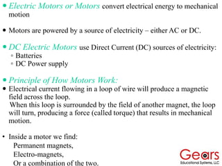
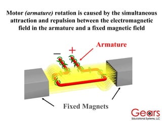
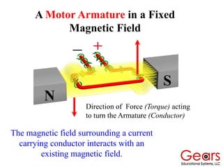
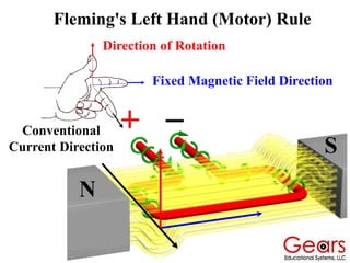
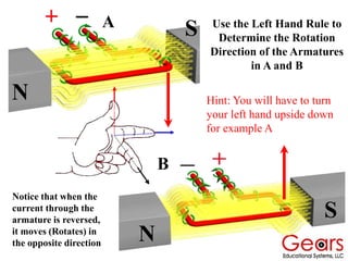
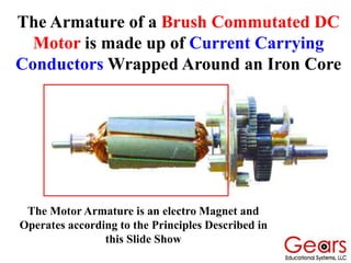
DC MOTORS
 Motors convert electric energy to
mechanical motion.
Either an AC or DC electrical energy source
serves as the input to the motor.
The result is mechanical motion of the output
shaft, that is a rotation about or a translation
along the shaft, provided the load carried by
the shaft does not exceed the maximum load
the motor is designed to carry.
There are numerous ways to design a motor, thus
there are many different types of motors.
The type of motor chosen for an application
depends on the characteristics needed in that
application.
These include:
◦How fast you want the object to move,
◦The weight, size of the object to be moved,
◦The cost and size of the motor,
◦The accuracy of position or speed control
needed.
The level of performance a motor can provide is
described by its parameters. These include:
Rated Speed
◦Speed measured in shaft revolutions per minute
(RPM)
Torque
◦Rotational force produced around a given point,
due to a force applied at a radius from that point,
measured in lb-ft (or, oz-in).
HorsePower = Speed x Torque / 5252.11...
◦A measure of work expended: 1 HP = 33,000 foot-
pounds per minute.
Torque-Speed performance of a motor
 Electric Motors or Motors convert electrical energy to mechanical
motion
 Motors are powered by a source of electricity – either AC or DC.
 DC Electric Motors use Direct Current (DC) sources of electricity:
◦ Batteries
◦ DC Power supply
 Principle of How Motors Work:
 Electrical current flowing in a loop of wire will produce a magnetic
field across the loop.
When this loop is surrounded by the field of another magnet, the loop
will turn, producing a force (called torque) that results in mechanical
motion.
• Inside a motor we find:
Permanent magnets,
Electro-magnets,
Or a combination of the two.
When current moves through a conductor a circular
magnetic field is induced around the conductor
Magnetic Field Lines
Negative Battery
Terminal
Positive Battery
Terminal
The Right Hand Rule
The direction of the magnetic field
surrounding the conductor can
be found using your
right hand
Position the thumb of your right hand
pointing in the direction of
conventional current (Positive to
Negative) and your fingers will wrap
around the conductor in the direction
of the induced magnetic field.
When current moves through a coiled conductor a
circular magnetic field is induced about the coil and
becomes an electromagnet.
Current and Magnetism in a Coil
Motor (armature) rotation is caused by the simultaneous
attraction and repulsion between the electromagnetic
field in the armature and a fixed magnetic field
Fixed Magnets
Armature
Induced Magnetic Field
(Due to current)
Fixed Magnetic Field
Force
A Conductor in a Fixed
Magnetic Field
A Current Carrying Conductor
in a Fixed Magnetic Field
N
S
A Motor Armature in a Fixed
Magnetic Field
The magnetic field surrounding a current
carrying conductor interacts with an
existing magnetic field.
Direction of Force (Torque) acting
to turn the Armature (Conductor)
Fleming's Left Hand (Motor) Rule
Determines the direction of DC current
carrying conductor in a fixed magnetic field
Thumb = Direction of
Conductor Motion Fore Finger = Direction of
Fixed Magnetic Field (N to S)
Middle Finger =
Conventional
Current Direction
Fleming's Left Hand (Motor) Rule
N
S
Direction of Rotation
Fixed Magnetic Field Direction
Conventional
Current Direction
N
S
N
S Use the Left Hand Rule to
Determine the Rotation
Direction of the Armatures
in A and B
Notice that when the
current through the
armature is reversed,
it moves (Rotates) in
the opposite direction
A
B
Hint: You will have to turn
your left hand upside down
for example A
Magnetic Forces Acting on Parallel
Current Carrying Conductors
X
Two parallel
conductors
carrying currents
in opposite
directions will
repel each other,
and they will set
up a polarized
magnetic field
between
themselves.
North
South
Magnetic Forces Acting on Parallel
Current Carrying Conductors
X
South
North
South
North
Wrapping current carrying conductors around
an iron core creates an electro magnet
The Armature of a Brush Commutated DC
Motor is made up of Current Carrying
Conductors Wrapped Around an Iron Core
The Motor Armature is an electro Magnet and
Operates according to the Principles Described in
this Slide Show
The End

DC motor powerpoint presentation by dynamo.ppt

  • 1.
  • 2.
     Motors convertelectric energy to mechanical motion. Either an AC or DC electrical energy source serves as the input to the motor. The result is mechanical motion of the output shaft, that is a rotation about or a translation along the shaft, provided the load carried by the shaft does not exceed the maximum load the motor is designed to carry.
  • 3.
    There are numerousways to design a motor, thus there are many different types of motors. The type of motor chosen for an application depends on the characteristics needed in that application. These include: ◦How fast you want the object to move, ◦The weight, size of the object to be moved, ◦The cost and size of the motor, ◦The accuracy of position or speed control needed.
  • 4.
    The level ofperformance a motor can provide is described by its parameters. These include: Rated Speed ◦Speed measured in shaft revolutions per minute (RPM) Torque ◦Rotational force produced around a given point, due to a force applied at a radius from that point, measured in lb-ft (or, oz-in). HorsePower = Speed x Torque / 5252.11... ◦A measure of work expended: 1 HP = 33,000 foot- pounds per minute. Torque-Speed performance of a motor
  • 5.
     Electric Motorsor Motors convert electrical energy to mechanical motion  Motors are powered by a source of electricity – either AC or DC.  DC Electric Motors use Direct Current (DC) sources of electricity: ◦ Batteries ◦ DC Power supply  Principle of How Motors Work:  Electrical current flowing in a loop of wire will produce a magnetic field across the loop. When this loop is surrounded by the field of another magnet, the loop will turn, producing a force (called torque) that results in mechanical motion. • Inside a motor we find: Permanent magnets, Electro-magnets, Or a combination of the two.
  • 6.
    When current movesthrough a conductor a circular magnetic field is induced around the conductor Magnetic Field Lines Negative Battery Terminal Positive Battery Terminal
  • 7.
    The Right HandRule The direction of the magnetic field surrounding the conductor can be found using your right hand Position the thumb of your right hand pointing in the direction of conventional current (Positive to Negative) and your fingers will wrap around the conductor in the direction of the induced magnetic field.
  • 8.
    When current movesthrough a coiled conductor a circular magnetic field is induced about the coil and becomes an electromagnet. Current and Magnetism in a Coil
  • 9.
    Motor (armature) rotationis caused by the simultaneous attraction and repulsion between the electromagnetic field in the armature and a fixed magnetic field Fixed Magnets Armature
  • 10.
    Induced Magnetic Field (Dueto current) Fixed Magnetic Field Force A Conductor in a Fixed Magnetic Field A Current Carrying Conductor in a Fixed Magnetic Field
  • 11.
    N S A Motor Armaturein a Fixed Magnetic Field The magnetic field surrounding a current carrying conductor interacts with an existing magnetic field. Direction of Force (Torque) acting to turn the Armature (Conductor)
  • 12.
    Fleming's Left Hand(Motor) Rule Determines the direction of DC current carrying conductor in a fixed magnetic field Thumb = Direction of Conductor Motion Fore Finger = Direction of Fixed Magnetic Field (N to S) Middle Finger = Conventional Current Direction
  • 13.
    Fleming's Left Hand(Motor) Rule N S Direction of Rotation Fixed Magnetic Field Direction Conventional Current Direction
  • 14.
    N S N S Use theLeft Hand Rule to Determine the Rotation Direction of the Armatures in A and B Notice that when the current through the armature is reversed, it moves (Rotates) in the opposite direction A B Hint: You will have to turn your left hand upside down for example A
  • 15.
    Magnetic Forces Actingon Parallel Current Carrying Conductors X Two parallel conductors carrying currents in opposite directions will repel each other, and they will set up a polarized magnetic field between themselves. North South
  • 16.
    Magnetic Forces Actingon Parallel Current Carrying Conductors X South North South North Wrapping current carrying conductors around an iron core creates an electro magnet
  • 17.
    The Armature ofa Brush Commutated DC Motor is made up of Current Carrying Conductors Wrapped Around an Iron Core The Motor Armature is an electro Magnet and Operates according to the Principles Described in this Slide Show
  • 18.