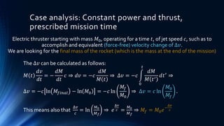
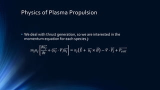
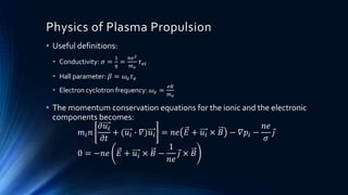
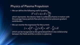
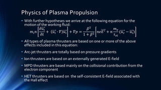
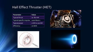
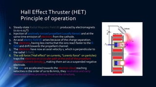
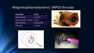
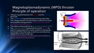
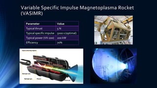
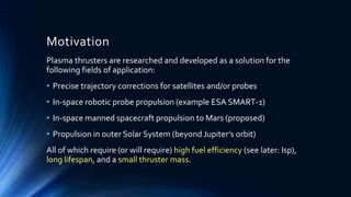
Plasma thrusters are being researched and developed for applications requiring high fuel efficiency, long lifespan, and low thruster mass. These include precise satellite trajectory corrections, in-space robotic and manned spacecraft propulsion. Plasma thrusters work by ionizing propellant and accelerating it using electric and magnetic fields. Common types include Hall Effect Thrusters (HET), Magnetoplasmadynamic (MPD) thrusters, Variable Specific Impulse Magnetoplasma Rocket (VASIMR), and Electrodeless Lorentz Force (ELF) thrusters. Each uses different combinations of electric and magnetic fields to generate thrust from the accelerated ionized propellant.

![Thrust, Power, Specific Impulse
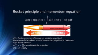
𝑝 𝑡 = 𝑀 𝑡 𝑣 𝑡 +
0
𝑡
𝑚 𝑡′ 𝑣 𝑡′ − 𝑐 𝑡′ 𝑑𝑡′
𝑑𝑝
𝑑𝑡
= 0 ⇒ 𝑀
𝑑𝑣
𝑑𝑡
+ 𝑣
𝑑𝑀
𝑑𝑡
+ 𝑚 𝑣 − 𝑐 = 0;
𝑚 ≡ −
𝑑𝑀
𝑑𝑡
;
⇒ 𝑀
𝑑𝑣
𝑑𝑡
= 𝑐
𝑑𝑀
𝑑𝑡
⇒ 𝑀
𝑑𝑣
𝑑𝑡
= −𝑐 𝑚
Thrust: 𝐹 = 𝑐 𝑚 [𝑁]
Calculating the thrust (accelerating force on the rocket structure) in a vacuum:
Total momentum change of the system (rocket + propellant) must be zero:](https://image.slidesharecdn.com/ec0b05d4-4a73-4d3a-b198-22d73ae3c8af-160119132022/85/Plasma-thrusters-PP-5-320.jpg)
![Thrust, Power, Specific Impulse
𝐸 𝑘 =
1
2
𝑀𝑣2 +
0
𝑡
1
2
𝑚 𝑡′ 𝑣 𝑡′ − 𝑐 𝑡′ 2 𝑑𝑡′
𝑑𝐸 𝑘
𝑑𝑡
= 𝑀𝑣
𝑑𝑣
𝑑𝑡
+
1
2
𝑣2
𝑑𝑀
𝑑𝑡
+
1
2
𝑚 𝑣2 + 𝑐2 − 2𝑣𝑐 ;
𝑀𝑣
𝑑𝑣
𝑑𝑡
= 𝑐 𝑚𝑣;
𝑑𝑀
𝑑𝑡
= − 𝑚;
⇒
𝑑𝐸 𝑘
𝑑𝑡
=
1
2
𝑚𝑐2
Kinetic power:
𝑑𝐸 𝑘
𝑑𝑡
=
1
2
𝑚𝑐2
𝐽𝑠−1
𝑜𝑟 [𝑊]
From the kinetic energy of the total system (rocket + propellant), we can calculate
the kinetic energy per unit time (kinetic power) of the exhaust jet:](https://image.slidesharecdn.com/ec0b05d4-4a73-4d3a-b198-22d73ae3c8af-160119132022/85/Plasma-thrusters-PP-6-320.jpg)
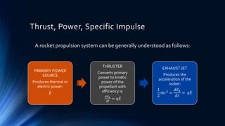
![Thrust, Power, Specific Impulse
Until now we have the following quantities:
• Thrust: 𝐹 = 𝑐 𝑚
• Kinetic power:
𝑑𝐸 𝑘
𝑑𝑡
=
1
2
𝑚𝑐
We can define another useful quantity, specific impulse, which measures
how much momentum is produced per unit mass (or weight) of expended
propellant:
• 𝐼𝑠𝑝1 =
𝐹
𝑚𝑔
=
𝑐 𝑚
𝑚𝑔
=
Δ𝑝
∆𝑚𝑔
=
𝑐
𝑔
[𝑠]
• 𝐼𝑠𝑝2 =
𝐹
𝑚
=
Δ𝑝
∆𝑚
= 𝑐 𝑚𝑠−1
Where 𝑔 = 9.81 𝑚𝑠−2 is the standard gravitational acceleration at sea
level.
The two definitions are interchangeable: 𝐼𝑠𝑝2 = 𝑔𝐼𝑠𝑝1](https://image.slidesharecdn.com/ec0b05d4-4a73-4d3a-b198-22d73ae3c8af-160119132022/85/Plasma-thrusters-PP-8-320.jpg)