Downloaded 24 times
![PLASMA PROPELLED ROCKET ENGINE
Dept. of Mech. Engg, KLE Dr. MSSCET, Belagavi. Page 17
References
[1] DanM. Goebel and Ira Katz. Wiley, -“Fundamentals of Electric
Propulsion: Ion and Hall Thrusters.” 2008, pg. 124-131.
[2] http://www.nasa.gov
[3] http://www.princeton.edu/~achaney/Magnetoplasmadynamic_thruster
[4] https://en.wikipedia.org/wiki/Ion_thruster](https://image.slidesharecdn.com/seminarreportfinal-170820173624/75/A-Seminar-on-Plasma-Propelled-Rocket-Engine-17-2048.jpg)

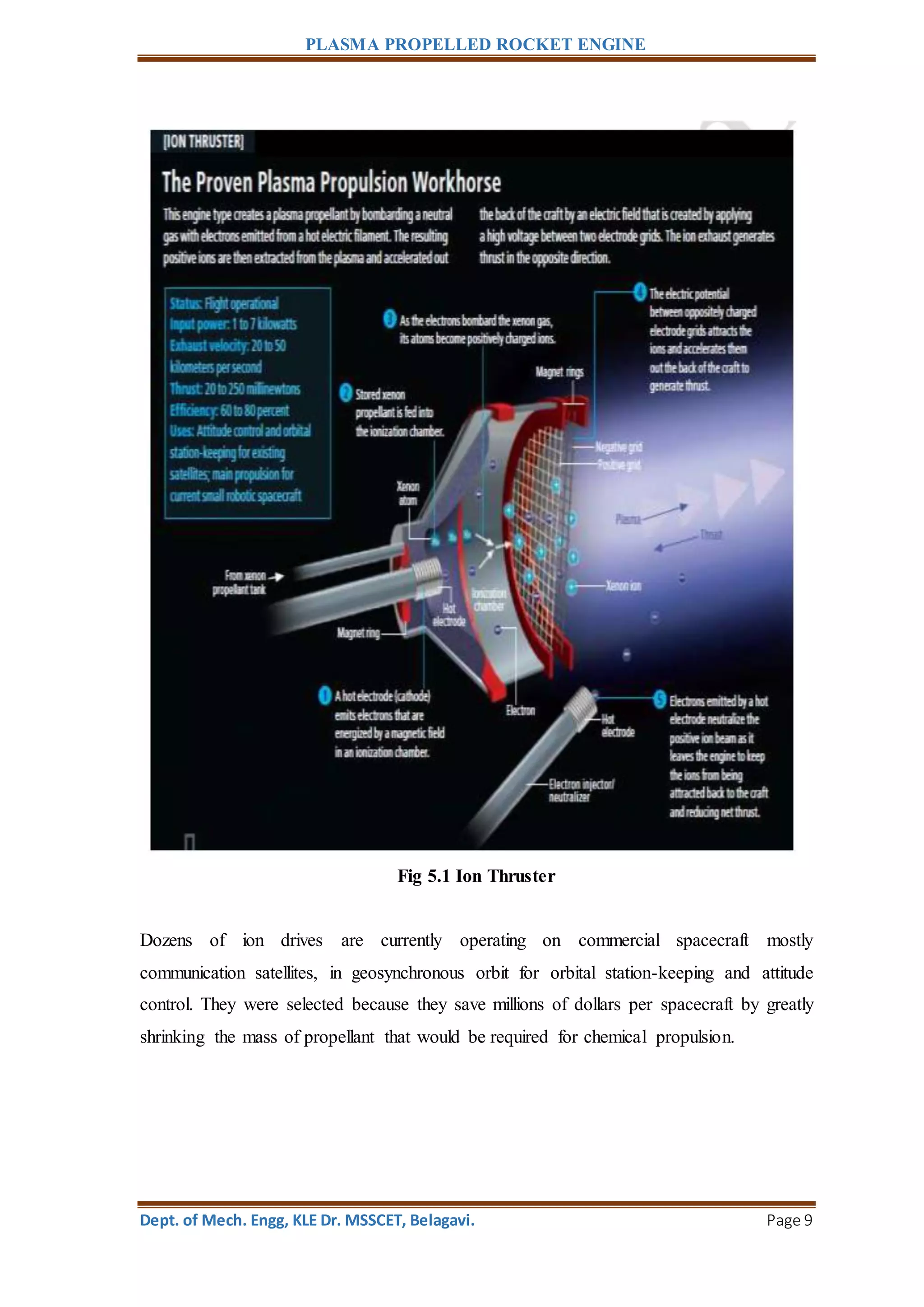
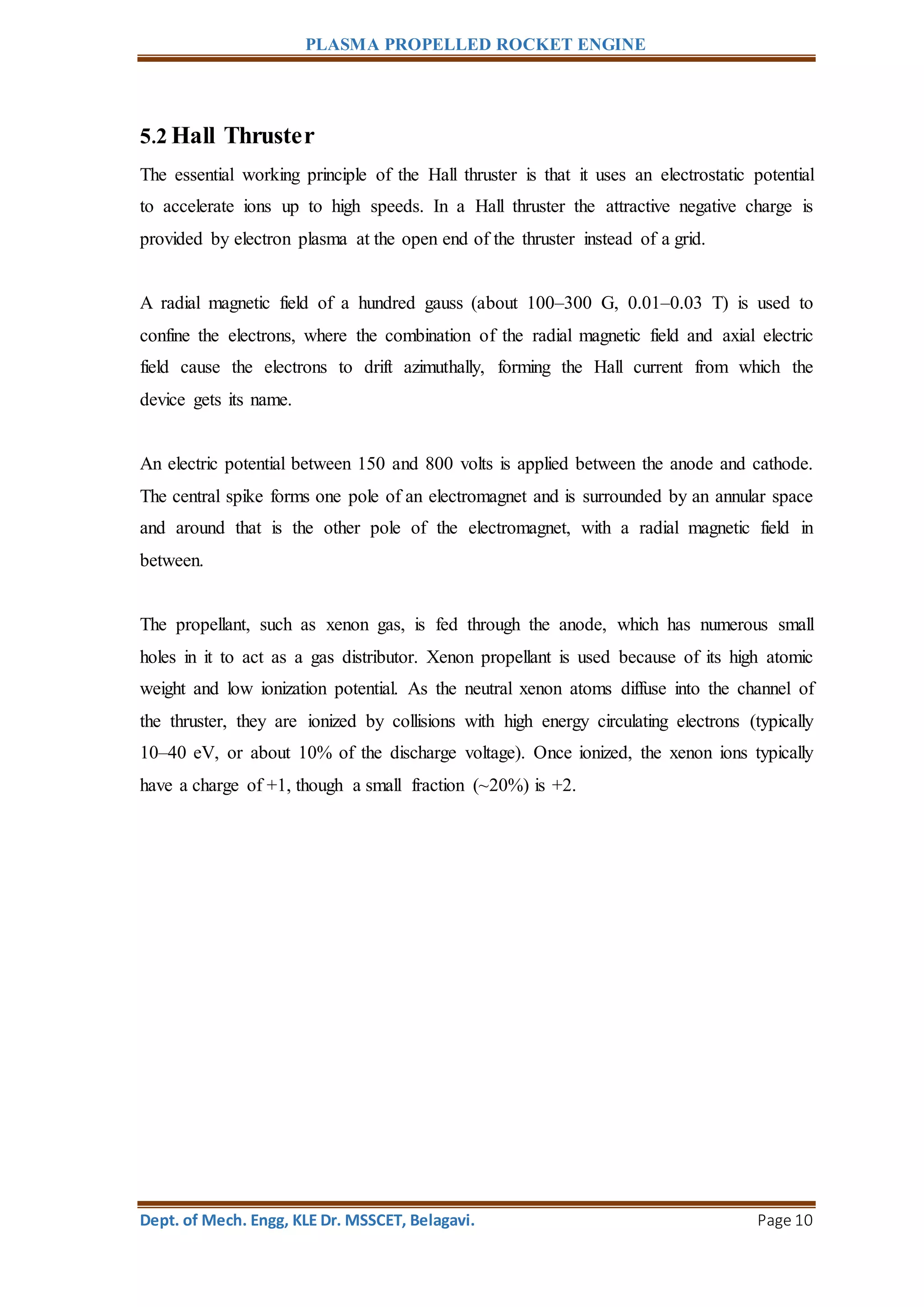
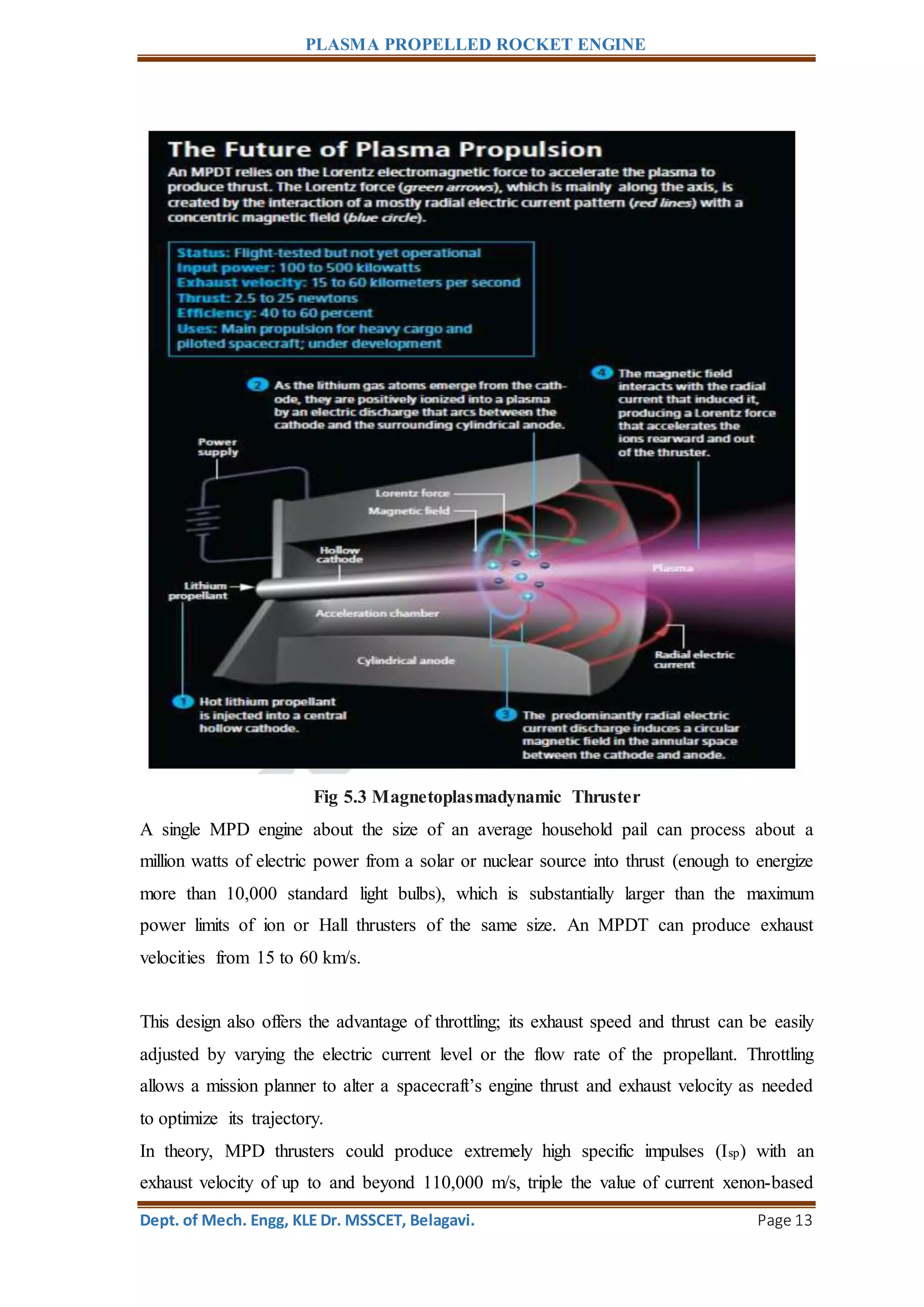
This document discusses different types of plasma propelled rocket engines. It begins by introducing plasma rocket engines and their advantages over traditional chemical rocket engines, notably much higher efficiency and specific impulse. It then describes three main types of plasma engines: ion drives, Hall thrusters, and magnetoplasmadynamic thrusters. Ion drives use electric and magnetic fields to ionize and accelerate propellant like xenon, producing thrust through ion exhaust. Hall thrusters also use electric and magnetic fields to ionize and accelerate propellant but do so through electron drift. Magnetoplasmadynamic thrusters generate thrust by ohmic heating of propellant in a magnetic nozzle.


![1159 voronka[1]](https://cdn.slidesharecdn.com/ss_thumbnails/u6ur9dkkroaacb6r2m1z-signature-fabe374f978bfb273f92443e2c8243d3e294d623a7c677008fe136d7284f57a9-poli-140825181532-phpapp01-thumbnail.jpg?width=640&height=640&fit=bounds)


