SlideShare a Scribd company logo
1 of 19
Download to read offline
Propagating Magnetic Wave Accelerator (PMWAC) 
for Manned Deep Space Missions 
Propagating Magnetic Field 
Magnetized Plasma Toroid (from 2D MHD calculation) 
Helical Transmission Coil 
Parameter First Stage Final 
System length 5 m 25 m 
Plasma mass mp : 0.2 mg D2 (same) 
Final plasma velocity: 3x10⁵ m/sec (Isp = 30,000 s) 1x10⁶ m/s 
Acceleration (Force): 2x10¹⁰ m/s (4 kN) (same) 
Thrust Power (0.2 kHz rep) 2 MW 20 MW
Propulsion Requirements for Deep Space 
Missions 
• High Specific Power - α=(kWthrust/kgspaceship) 
α > 1 kW/kg 
• High (and variable) exhaust velocities vex 
max vex ~ 104 km/s (Isp = vex/g ~ 106 s) 
• Continuous power with near zero maintenance for 
months
Trip Time and the Specific Power 
Requirement 
Accelerating a mass Mss over a time=τ=implies a power P where: 
Mssvc 
τ 
≈ 
2 
2 
P 
One defines a characteristic velocity vc: 
vc = (2α τ )1/ 2 
where=α=is the specific power. 
The trip time=τtrip=to go a distance L is given roughly as: 
(months) 2L(astronomical units) 
1/ 3 
2 / 3 
trip 
2 L 
c 
trip 
(kW/ kg) 
v 
α 
τ ≈ τ =
Rapid Manned Mars Mission Power Requirement 
30 day 
stay 
Mars 
Sun 
Earth 
2 1 0 1 2 
2 
1 
0 
1 
2 
A.U. 
A.U. 
0 10 20 30 40 50 60 70 80 90 
3.5 
3 
2.5 
2 
1.5 
1 
0.5 
0 
time in days 
Isp 
(104 s) 
S(astronomical units) 2 (kW/ kg) 8 3 ≈ 
[ ] 1 
(months) 
τ 
α = 
for Mss ~ 20 MT, Pthrust = 20 MW
Velocity and Energy Requirements for Deep 
Space Missions 
(α =1 kW/kg) 
Destination xtrip ~ 2 A.U. (Mars) ttrip ~ 3 months 
xtrip ~ 10 A.U. (Jupiter) ttrip ~ 12 months 
Characteristic vMars ~ 125 km/sec 
Velocity vJupiter ~ 250 km/sec 
Specific εMars ~ 8x10⁹ J/kg 
Energy εJupiter ~ 3x10¹⁰ J/kg 
Propulsion System Exhaust (km/sec) 
Chemical 5 
Electric 30 
FRC at RPPL 250 
Thermal Fusion 2000 
Fuel Specific Energy 
Chemical 1x10⁷ J/kg 
Fission 5x10¹³ J/kg 
Fusion 1x10¹⁵ J/kg 
α=vchar 
2/2ttrip 
ε=vchar 
2/2 =α ttrip 
Nuclear Power is Necessary for Deep Space Travel
Current and Planned “Breakeven” Fusion Experiments 
ITER (MFE) PHD NIF (ICF)
ICF 
electron thermal 
conduction 
MTF ICF 
MFE 
PHD 
MFE 
CT Classical 
Tokamak 
ITER89-P 
Mag. Force > 
Material Strength 
1020 1022 1024 1026 1028 1030 1032 
Density (m-3) 
1012 
109 
106 
103 
100 
Plasma Energy (J) 
Plasma Density and Energy Regimes 
for Different Fusion Concepts
⇔ 
Shiva Star Facility for MTF 
~ 10 MJ 
2 Auto Batteries 
~10 MJ 
High Voltage Energy Storage 
V~ 120 kV 
Low Voltage Storage 
V~ 12 V
Pulsed High Density (PHD) Fusion Basics 
•Fusion reaction rate R: 
R = nDnT <σ DT v> 
At Tp = 10 keV, 
<σ DT v> ≅ 10-22 m3/sec 
•For space-based fusion: 
G ~ 3 (thermal electrical) 
nτburn ~ 1x10²⁰ m-3 sec 
To maintain burn: τE ~ τburn 
•Lawson Criterion: ~ nτE ~ 1x10²⁰ m-3 sec 
•Plasma pressure < Magnet Yield Limit (2x10⁴ Atm): 
(Tp = 10 keV) nfus = 1x1024 m-3 
and τE = 100 μsec
Field Reversed Configuration (FRC) Propulsion 
Azimuthal Current 
Center Line 
External Field Coils 
Closed Field Lines 
Separatrix 
Open External Field Lines 
•Propellant (plasma) is magnetically insulated from thruster wall 
•No plasma detachment problem 
-plasma (FRC) contained separate a magnetic envelope 
•Plasma is thermally isolated from thruster walls 
-fully ionized plasma is vacuum isolated 
•Both thrust and Isp can be varied easily over a wide range 
-change of gas fill pressure is all that is required 
•Thrust and Isp are decoupled from plasma thermal energy 
-with vdir >> vth theoretical efficiency can approach unity 
•Enables a direct, simple method to achieve fusion propulsion 
with minimum investment
PHD Fusion Rocket 
Flowing Liquid Metal 
Heat Exchanger/ Breeder 
~ 20 m 
BURN CHAMBER 
(Rc ~ 13 mm) 
5 m 
1 m 
Magnetic 
Expansion Nozzle Accelerator Source 
From past FRC experiments: τE ~ τN = 1.3x10⁻¹² xs rp 
2 n1/2 (xs = rp/Rc) 
with n = nfus, rp =1 cm (Rc = 1.3 cm) 
with lp/rp= 5 Ep= 50 kJ 
rep rate = 200 Hz 17 MW directed thrust power 
•FRC formed at low energy (~5 kJ) and relatively low density (~1021 m-3) 
•FRC accelerated and compressed by low energy propagating magnetic field (< 0.4 T). 
•FRC is decelerated, compressed, and heated as it enters high field burn chamber 
•FRC expands and cools converting thermal and magnetic energy into directed thrust
FRC Acceleration and Heating Expts. at UW 
Formation FRC mass: Accelerator Confinement 
0 2.0 4.0 
Axial Position (m) 
Shot 238 
Radius (cm) 40 
0 
0.4 mg Deuterium 
FRC terminal velocity: 
vd = 2.5x10⁵ m/s 
Average FRC acceleration: 
(5 - 30 μsec) 
aavg = 9x10⁹ m/s2 
FRC Energy (final) 
15 kJ 
Thermal Conversion of 
FRC directed Energy 
First pass 
of FRC FRC after reflection 
in downstream mirror 
0 100 200 
0.6 
0.4 
0.2 
0 
Tp 
(keV) 
time (μsec)
FRC Acceleration Method Employed in UW Expts. 
Bupstream 
Bdc 
Bdown 
0 
•Upper plot of flux contours taken from numerical calculations for discharge 1647 
during the acceleration of an FRC at UW. 
•Bottom plot illustrates phasing of the accelerator coils 
Each coil in turn is switched on for one complete cycle. 
Phase of each coil at time of calculation is indicated by arrow
Propagating Magnetic Wave Accelerator 
For transmission line: 
2 1 
vp = 2 = 
Z L 
For shell capacitor (per unit length): 
2 Rc 0 S 
Inductance (per unit length): 
From these eqs. Solving for Rc 
2V S 
and finally for the phase velocity: 
Power Supply Switch 
CP 
L 
C 
Inner helical conductor 
Dielectric Shell 
Outer conductor 
C 
LC 
V 
C 
π ε κ ε 
= 
2 n2 
L = μ0 πRc 
c2 B2 
Rc 
κ ε 
= 
c 
2 n 
1/ 2 
S 
3c 
R 
2V 
vP 
π 


κ ε 
= 
m/ s 
v 1.35x10 1.5 
R n 
c 
5 
P = 
εS = 5x10⁶ V/m 
κ = 2500*ε0 
V = ± 25 kV 
BaTiO3 
1 cm 
vP = 106 m/s B = 0.5 T 
for Rc = 5.5 cm n = 10 turns/m
PMWAC SPICE Calculation for Constant Z 
1 6 10 
Vacuum load Dissipative load (plasma) 
1 6 10 1 6 10 
30 
20 
10 
0 
-10 
-1 0 1 2 3 4 -1 0 1 2 3 4 
213456 
X4 
sw 
V0 
1 
17 
16 
IL1 
17 
10 
Δ 
11 
VLoad 
1 
L1 2 
24 
64n 
RG 
10K 
C1 
100n 
3 
L2 
64n 
13 
C2 
100n 
4 
L3 
64n 
14 
C3 
100n 
5 
L4 
64n 
15 
C4 
100n 
6 
L5 
64n 
18 
C5 
100n 
7 
L6 
64n 
19 
C6 
100n 
8 
L7 
64n 
20 
C7 
100n 
21 
L8 
64n 
12 
R2 
.0001 
R3 
.0001 
R4 
.0001 
R5 
.0001 
R6 
.0001 
R7 
.0001 
R8 
.0001 
10 
RLoad 
1 
11 
10 
ILoad 
11 
25 
CS 
1u 
1 
Δ 
25 
VSource 
V6 
IL10 
22 
L9 
64n 
23 
C9 
100n 
R9 
.0001 
R1 
.0001 
9 
10 
L10 
64n 
11 
C10 
100n 
R10 
.0001 
C8 
100n 
10 
11 
24 
LS 
200n 
24 IR1 
K12 
L1 
K13 
L1 
K14 
L1 
K23 
L2 
K24 
L2 
K25 
L2 
K34 
L3 
K35 
L3 
K45 
L4 
K36 
L3 
K46 
L4 
K47 
L4 
K56 
L5 
K57 
L5 
K58 
L5 
K67 
L6 
K68 
L6 
K78 
L7 
K69 
L6 
K79 
L7 
K710 
L7 
K89 
L8 
K810 
L8 
K910 
L9 
IL6 
3 
40 
I 
(kA) 
Time (μsec) Time (μsec)
R 
(m) 
0.2 
0 
0.2 
6 5 4 3 2 1 0 
Z (m) 
Time 
(μsec) 
5 
10 
15 
17.5 
20 
Resistive 2D MHD Calculation of FRC with 
Propagating Magnetic Field (0.4 T) 
6.0 
4.0 
2.0 
0 
vFRC 
(105 m/s) 
Vaccel = 30 kV, MFRC = 
0 5 10 15 20 
Time (μsec) 
T 
(keV) 
1.2 
0.8 
0.4 
0 
Ti 
Te
Time 
(μsec) 
5 
10 
15 
20 
25 
30 
PMWAC Can Also Be Employed to Provide 
High Isp, High Thrust Electrical propulsion 
R 
(m) 
Z 
(m) 
0.2 
0 
0.2 
6 5 4 3 2 1 
0 
V = ± 3.5 kV ⇔ Bacc = 0.2 T 
a = 1.2x10⁹ g 
0 5 10 15 20 25 30 
vFRC 
(105 m/s) 
4.0 
3.0 
2.0 
1.0 
0 
MFRC = 0.2 mg 
T (μsec)
Inductive Magnetized Plasma Accelerator Source 
Developed with NASA STTR funding at MSNW 
Capacitor 
Gas feed 
Strip-line 
feedplates 
SS Switch Coil straps 
Magnetic field 
Magnetized plasma
PMWAC Development Program 
Phase 1: 
•Determine Accelerator Requirements and Parameters 
•Design Proto-Accelerator for Electrical Validation 
•Construct Accelerator and Measure Electrical Performance 
•Develop Full Electrical Model with Plasma Interaction 
Phase II: 
•Design and Construct Full-scale Accelerator 
•Install Accelerator and Demonstrate FRC Acceleration 
to Fusion Velocities (~106 m/s).

More Related Content

What's hot

Solucionario serway cap 18
Solucionario serway cap 18Solucionario serway cap 18
Solucionario serway cap 18Carlo Magno
 
Micro asteroidprospector
Micro asteroidprospectorMicro asteroidprospector
Micro asteroidprospectorClifford Stone
 
MET Energy Resolution in Pileup Minimum Bias Events using 7 TeV LHC Data
MET Energy Resolution in Pileup Minimum Bias Events using 7 TeV LHC DataMET Energy Resolution in Pileup Minimum Bias Events using 7 TeV LHC Data
MET Energy Resolution in Pileup Minimum Bias Events using 7 TeV LHC Datakuhanw
 
thermal science Ch 04
thermal science Ch 04thermal science Ch 04
thermal science Ch 04尚儒 吳
 
Eh4 energy harvesting due to random excitations and optimal design
Eh4   energy harvesting due to random excitations and optimal designEh4   energy harvesting due to random excitations and optimal design
Eh4 energy harvesting due to random excitations and optimal designUniversity of Glasgow
 
International Journal of Computational Engineering Research(IJCER)
International Journal of Computational Engineering Research(IJCER)International Journal of Computational Engineering Research(IJCER)
International Journal of Computational Engineering Research(IJCER)ijceronline
 
Offshore windfarm design - Lesson 7 park design
Offshore windfarm design - Lesson 7 park designOffshore windfarm design - Lesson 7 park design
Offshore windfarm design - Lesson 7 park designJohan Antonissen
 
Solucionario serway cap 32
Solucionario serway cap 32Solucionario serway cap 32
Solucionario serway cap 32Carlo Magno
 

What's hot (20)

Anschp26
Anschp26Anschp26
Anschp26
 
Solucionario serway cap 18
Solucionario serway cap 18Solucionario serway cap 18
Solucionario serway cap 18
 
Proceeding - PANIC
Proceeding - PANICProceeding - PANIC
Proceeding - PANIC
 
Base excitation of dynamic systems
Base excitation of dynamic systemsBase excitation of dynamic systems
Base excitation of dynamic systems
 
Micro asteroidprospector
Micro asteroidprospectorMicro asteroidprospector
Micro asteroidprospector
 
MET Energy Resolution in Pileup Minimum Bias Events using 7 TeV LHC Data
MET Energy Resolution in Pileup Minimum Bias Events using 7 TeV LHC DataMET Energy Resolution in Pileup Minimum Bias Events using 7 TeV LHC Data
MET Energy Resolution in Pileup Minimum Bias Events using 7 TeV LHC Data
 
Lecture 12
Lecture 12Lecture 12
Lecture 12
 
UCISem
UCISemUCISem
UCISem
 
Thesis
ThesisThesis
Thesis
 
thermal science Ch 04
thermal science Ch 04thermal science Ch 04
thermal science Ch 04
 
Ch17 ssm
Ch17 ssmCh17 ssm
Ch17 ssm
 
Solution a ph o 3
Solution a ph o 3Solution a ph o 3
Solution a ph o 3
 
Anschp39
Anschp39Anschp39
Anschp39
 
Eh4 energy harvesting due to random excitations and optimal design
Eh4   energy harvesting due to random excitations and optimal designEh4   energy harvesting due to random excitations and optimal design
Eh4 energy harvesting due to random excitations and optimal design
 
International Journal of Computational Engineering Research(IJCER)
International Journal of Computational Engineering Research(IJCER)International Journal of Computational Engineering Research(IJCER)
International Journal of Computational Engineering Research(IJCER)
 
ECNG 3013 E
ECNG 3013 EECNG 3013 E
ECNG 3013 E
 
YSchutz_PPTWin
YSchutz_PPTWinYSchutz_PPTWin
YSchutz_PPTWin
 
Offshore windfarm design - Lesson 7 park design
Offshore windfarm design - Lesson 7 park designOffshore windfarm design - Lesson 7 park design
Offshore windfarm design - Lesson 7 park design
 
Solucionario serway cap 32
Solucionario serway cap 32Solucionario serway cap 32
Solucionario serway cap 32
 
Anschp29
Anschp29Anschp29
Anschp29
 

Similar to PMWAC for Deep Space Nuclear Fusion Propulsion

Em drive basic theory
Em drive basic theoryEm drive basic theory
Em drive basic theoryTibor Szász
 
Solucionario serway cap 27
Solucionario serway cap 27Solucionario serway cap 27
Solucionario serway cap 27Carlo Magno
 
636883main fdr talk_niac_2012_final
636883main fdr talk_niac_2012_final636883main fdr talk_niac_2012_final
636883main fdr talk_niac_2012_finalClifford Stone
 
Superconducting Generators
Superconducting GeneratorsSuperconducting Generators
Superconducting GeneratorsRafed Hossain
 
Solved problems to_chapter_09
Solved problems to_chapter_09Solved problems to_chapter_09
Solved problems to_chapter_09Shah Zaib
 
AP Physics 1 Equations
AP Physics 1 Equations AP Physics 1 Equations
AP Physics 1 Equations Matthew Long
 
2014 APS March Meeting Presentation
2014 APS March Meeting Presentation2014 APS March Meeting Presentation
2014 APS March Meeting PresentationCorbyn Mellinger
 
Chenming-Hu-ch2-slides.ppt
Chenming-Hu-ch2-slides.pptChenming-Hu-ch2-slides.ppt
Chenming-Hu-ch2-slides.pptAkash510271
 
Chenming-Hu-ch2-slides.ppt
Chenming-Hu-ch2-slides.pptChenming-Hu-ch2-slides.ppt
Chenming-Hu-ch2-slides.pptAumBuddhadev
 
Transmission line zero seq reactance
Transmission line zero seq reactanceTransmission line zero seq reactance
Transmission line zero seq reactanceShyamkant Vasekar
 
Solucionario serway cap 33
Solucionario serway cap 33Solucionario serway cap 33
Solucionario serway cap 33Carlo Magno
 
Transmission and distribution system design
Transmission and distribution system designTransmission and distribution system design
Transmission and distribution system designBikash Gyawali
 

Similar to PMWAC for Deep Space Nuclear Fusion Propulsion (20)

Icops 2011 June
Icops 2011 JuneIcops 2011 June
Icops 2011 June
 
Em drive basic theory
Em drive basic theoryEm drive basic theory
Em drive basic theory
 
The plasmamagnet
The plasmamagnetThe plasmamagnet
The plasmamagnet
 
Solucionario serway cap 27
Solucionario serway cap 27Solucionario serway cap 27
Solucionario serway cap 27
 
Sm chapter27
Sm chapter27Sm chapter27
Sm chapter27
 
636883main fdr talk_niac_2012_final
636883main fdr talk_niac_2012_final636883main fdr talk_niac_2012_final
636883main fdr talk_niac_2012_final
 
Maxwell Equations (2)
Maxwell Equations (2)Maxwell Equations (2)
Maxwell Equations (2)
 
Superconducting Generators
Superconducting GeneratorsSuperconducting Generators
Superconducting Generators
 
Solved problems to_chapter_09
Solved problems to_chapter_09Solved problems to_chapter_09
Solved problems to_chapter_09
 
CUPC Oct 14, 2015
CUPC Oct 14, 2015CUPC Oct 14, 2015
CUPC Oct 14, 2015
 
AP Physics 1 Equations
AP Physics 1 Equations AP Physics 1 Equations
AP Physics 1 Equations
 
2014 APS March Meeting Presentation
2014 APS March Meeting Presentation2014 APS March Meeting Presentation
2014 APS March Meeting Presentation
 
Presentation.docx.ppt
Presentation.docx.pptPresentation.docx.ppt
Presentation.docx.ppt
 
Chenming-Hu-ch2-slides.ppt
Chenming-Hu-ch2-slides.pptChenming-Hu-ch2-slides.ppt
Chenming-Hu-ch2-slides.ppt
 
Chenming-Hu-ch2-slides.ppt
Chenming-Hu-ch2-slides.pptChenming-Hu-ch2-slides.ppt
Chenming-Hu-ch2-slides.ppt
 
Doppler radar
Doppler radarDoppler radar
Doppler radar
 
Transmission line zero seq reactance
Transmission line zero seq reactanceTransmission line zero seq reactance
Transmission line zero seq reactance
 
Solucionario serway cap 33
Solucionario serway cap 33Solucionario serway cap 33
Solucionario serway cap 33
 
Sm chapter33
Sm chapter33Sm chapter33
Sm chapter33
 
Transmission and distribution system design
Transmission and distribution system designTransmission and distribution system design
Transmission and distribution system design
 

More from Clifford Stone (20)

Zubrin nov99
Zubrin nov99Zubrin nov99
Zubrin nov99
 
Xray telescopeconcept
Xray telescopeconceptXray telescopeconcept
Xray telescopeconcept
 
Xray interferometry
Xray interferometryXray interferometry
Xray interferometry
 
Wpafb blue bookdocuments
Wpafb blue bookdocumentsWpafb blue bookdocuments
Wpafb blue bookdocuments
 
What gov knows_about_ufos
What gov knows_about_ufosWhat gov knows_about_ufos
What gov knows_about_ufos
 
Welcome oct02
Welcome oct02Welcome oct02
Welcome oct02
 
Weather jun02
Weather jun02Weather jun02
Weather jun02
 
Wassersug richard[1]
Wassersug richard[1]Wassersug richard[1]
Wassersug richard[1]
 
Washington, d.c., jul 26 27, 1952
Washington, d.c., jul 26 27, 1952Washington, d.c., jul 26 27, 1952
Washington, d.c., jul 26 27, 1952
 
Wash dc jul 19 to 20 1952
Wash dc jul 19 to 20 1952Wash dc jul 19 to 20 1952
Wash dc jul 19 to 20 1952
 
Vol4ch03
Vol4ch03Vol4ch03
Vol4ch03
 
Vol4ch02
Vol4ch02Vol4ch02
Vol4ch02
 
Vol4ch01
Vol4ch01Vol4ch01
Vol4ch01
 
Vol3ch16
Vol3ch16Vol3ch16
Vol3ch16
 
Vol3ch14
Vol3ch14Vol3ch14
Vol3ch14
 
Vol3ch13
Vol3ch13Vol3ch13
Vol3ch13
 
Vol3ch12
Vol3ch12Vol3ch12
Vol3ch12
 
Vol3ch11
Vol3ch11Vol3ch11
Vol3ch11
 
Vol3ch10
Vol3ch10Vol3ch10
Vol3ch10
 
Vol3ch09
Vol3ch09Vol3ch09
Vol3ch09
 

PMWAC for Deep Space Nuclear Fusion Propulsion

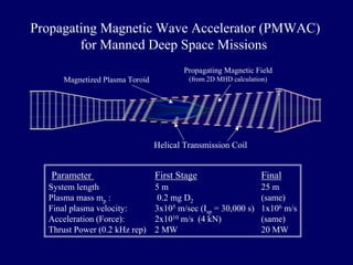
  • 1. Propagating Magnetic Wave Accelerator (PMWAC) for Manned Deep Space Missions Propagating Magnetic Field Magnetized Plasma Toroid (from 2D MHD calculation) Helical Transmission Coil Parameter First Stage Final System length 5 m 25 m Plasma mass mp : 0.2 mg D2 (same) Final plasma velocity: 3x10⁵ m/sec (Isp = 30,000 s) 1x10⁶ m/s Acceleration (Force): 2x10¹⁰ m/s (4 kN) (same) Thrust Power (0.2 kHz rep) 2 MW 20 MW
  • 2. Propulsion Requirements for Deep Space Missions • High Specific Power - α=(kWthrust/kgspaceship) α > 1 kW/kg • High (and variable) exhaust velocities vex max vex ~ 104 km/s (Isp = vex/g ~ 106 s) • Continuous power with near zero maintenance for months
  • 3. Trip Time and the Specific Power Requirement Accelerating a mass Mss over a time=τ=implies a power P where: Mssvc τ ≈ 2 2 P One defines a characteristic velocity vc: vc = (2α τ )1/ 2 where=α=is the specific power. The trip time=τtrip=to go a distance L is given roughly as: (months) 2L(astronomical units) 1/ 3 2 / 3 trip 2 L c trip (kW/ kg) v α τ ≈ τ =
  • 4. Rapid Manned Mars Mission Power Requirement 30 day stay Mars Sun Earth 2 1 0 1 2 2 1 0 1 2 A.U. A.U. 0 10 20 30 40 50 60 70 80 90 3.5 3 2.5 2 1.5 1 0.5 0 time in days Isp (104 s) S(astronomical units) 2 (kW/ kg) 8 3 ≈ [ ] 1 (months) τ α = for Mss ~ 20 MT, Pthrust = 20 MW
  • 5. Velocity and Energy Requirements for Deep Space Missions (α =1 kW/kg) Destination xtrip ~ 2 A.U. (Mars) ttrip ~ 3 months xtrip ~ 10 A.U. (Jupiter) ttrip ~ 12 months Characteristic vMars ~ 125 km/sec Velocity vJupiter ~ 250 km/sec Specific εMars ~ 8x10⁹ J/kg Energy εJupiter ~ 3x10¹⁰ J/kg Propulsion System Exhaust (km/sec) Chemical 5 Electric 30 FRC at RPPL 250 Thermal Fusion 2000 Fuel Specific Energy Chemical 1x10⁷ J/kg Fission 5x10¹³ J/kg Fusion 1x10¹⁵ J/kg α=vchar 2/2ttrip ε=vchar 2/2 =α ttrip Nuclear Power is Necessary for Deep Space Travel
  • 6. Current and Planned “Breakeven” Fusion Experiments ITER (MFE) PHD NIF (ICF)
  • 7. ICF electron thermal conduction MTF ICF MFE PHD MFE CT Classical Tokamak ITER89-P Mag. Force > Material Strength 1020 1022 1024 1026 1028 1030 1032 Density (m-3) 1012 109 106 103 100 Plasma Energy (J) Plasma Density and Energy Regimes for Different Fusion Concepts
  • 8. ⇔ Shiva Star Facility for MTF ~ 10 MJ 2 Auto Batteries ~10 MJ High Voltage Energy Storage V~ 120 kV Low Voltage Storage V~ 12 V
  • 9. Pulsed High Density (PHD) Fusion Basics •Fusion reaction rate R: R = nDnT <σ DT v> At Tp = 10 keV, <σ DT v> ≅ 10-22 m3/sec •For space-based fusion: G ~ 3 (thermal electrical) nτburn ~ 1x10²⁰ m-3 sec To maintain burn: τE ~ τburn •Lawson Criterion: ~ nτE ~ 1x10²⁰ m-3 sec •Plasma pressure < Magnet Yield Limit (2x10⁴ Atm): (Tp = 10 keV) nfus = 1x1024 m-3 and τE = 100 μsec
  • 10. Field Reversed Configuration (FRC) Propulsion Azimuthal Current Center Line External Field Coils Closed Field Lines Separatrix Open External Field Lines •Propellant (plasma) is magnetically insulated from thruster wall •No plasma detachment problem -plasma (FRC) contained separate a magnetic envelope •Plasma is thermally isolated from thruster walls -fully ionized plasma is vacuum isolated •Both thrust and Isp can be varied easily over a wide range -change of gas fill pressure is all that is required •Thrust and Isp are decoupled from plasma thermal energy -with vdir >> vth theoretical efficiency can approach unity •Enables a direct, simple method to achieve fusion propulsion with minimum investment
  • 11. PHD Fusion Rocket Flowing Liquid Metal Heat Exchanger/ Breeder ~ 20 m BURN CHAMBER (Rc ~ 13 mm) 5 m 1 m Magnetic Expansion Nozzle Accelerator Source From past FRC experiments: τE ~ τN = 1.3x10⁻¹² xs rp 2 n1/2 (xs = rp/Rc) with n = nfus, rp =1 cm (Rc = 1.3 cm) with lp/rp= 5 Ep= 50 kJ rep rate = 200 Hz 17 MW directed thrust power •FRC formed at low energy (~5 kJ) and relatively low density (~1021 m-3) •FRC accelerated and compressed by low energy propagating magnetic field (< 0.4 T). •FRC is decelerated, compressed, and heated as it enters high field burn chamber •FRC expands and cools converting thermal and magnetic energy into directed thrust
  • 12. FRC Acceleration and Heating Expts. at UW Formation FRC mass: Accelerator Confinement 0 2.0 4.0 Axial Position (m) Shot 238 Radius (cm) 40 0 0.4 mg Deuterium FRC terminal velocity: vd = 2.5x10⁵ m/s Average FRC acceleration: (5 - 30 μsec) aavg = 9x10⁹ m/s2 FRC Energy (final) 15 kJ Thermal Conversion of FRC directed Energy First pass of FRC FRC after reflection in downstream mirror 0 100 200 0.6 0.4 0.2 0 Tp (keV) time (μsec)
  • 13. FRC Acceleration Method Employed in UW Expts. Bupstream Bdc Bdown 0 •Upper plot of flux contours taken from numerical calculations for discharge 1647 during the acceleration of an FRC at UW. •Bottom plot illustrates phasing of the accelerator coils Each coil in turn is switched on for one complete cycle. Phase of each coil at time of calculation is indicated by arrow
  • 14. Propagating Magnetic Wave Accelerator For transmission line: 2 1 vp = 2 = Z L For shell capacitor (per unit length): 2 Rc 0 S Inductance (per unit length): From these eqs. Solving for Rc 2V S and finally for the phase velocity: Power Supply Switch CP L C Inner helical conductor Dielectric Shell Outer conductor C LC V C π ε κ ε = 2 n2 L = μ0 πRc c2 B2 Rc κ ε = c 2 n 1/ 2 S 3c R 2V vP π κ ε = m/ s v 1.35x10 1.5 R n c 5 P = εS = 5x10⁶ V/m κ = 2500*ε0 V = ± 25 kV BaTiO3 1 cm vP = 106 m/s B = 0.5 T for Rc = 5.5 cm n = 10 turns/m
  • 15. PMWAC SPICE Calculation for Constant Z 1 6 10 Vacuum load Dissipative load (plasma) 1 6 10 1 6 10 30 20 10 0 -10 -1 0 1 2 3 4 -1 0 1 2 3 4 213456 X4 sw V0 1 17 16 IL1 17 10 Δ 11 VLoad 1 L1 2 24 64n RG 10K C1 100n 3 L2 64n 13 C2 100n 4 L3 64n 14 C3 100n 5 L4 64n 15 C4 100n 6 L5 64n 18 C5 100n 7 L6 64n 19 C6 100n 8 L7 64n 20 C7 100n 21 L8 64n 12 R2 .0001 R3 .0001 R4 .0001 R5 .0001 R6 .0001 R7 .0001 R8 .0001 10 RLoad 1 11 10 ILoad 11 25 CS 1u 1 Δ 25 VSource V6 IL10 22 L9 64n 23 C9 100n R9 .0001 R1 .0001 9 10 L10 64n 11 C10 100n R10 .0001 C8 100n 10 11 24 LS 200n 24 IR1 K12 L1 K13 L1 K14 L1 K23 L2 K24 L2 K25 L2 K34 L3 K35 L3 K45 L4 K36 L3 K46 L4 K47 L4 K56 L5 K57 L5 K58 L5 K67 L6 K68 L6 K78 L7 K69 L6 K79 L7 K710 L7 K89 L8 K810 L8 K910 L9 IL6 3 40 I (kA) Time (μsec) Time (μsec)
  • 16. R (m) 0.2 0 0.2 6 5 4 3 2 1 0 Z (m) Time (μsec) 5 10 15 17.5 20 Resistive 2D MHD Calculation of FRC with Propagating Magnetic Field (0.4 T) 6.0 4.0 2.0 0 vFRC (105 m/s) Vaccel = 30 kV, MFRC = 0 5 10 15 20 Time (μsec) T (keV) 1.2 0.8 0.4 0 Ti Te
  • 17. Time (μsec) 5 10 15 20 25 30 PMWAC Can Also Be Employed to Provide High Isp, High Thrust Electrical propulsion R (m) Z (m) 0.2 0 0.2 6 5 4 3 2 1 0 V = ± 3.5 kV ⇔ Bacc = 0.2 T a = 1.2x10⁹ g 0 5 10 15 20 25 30 vFRC (105 m/s) 4.0 3.0 2.0 1.0 0 MFRC = 0.2 mg T (μsec)
  • 18. Inductive Magnetized Plasma Accelerator Source Developed with NASA STTR funding at MSNW Capacitor Gas feed Strip-line feedplates SS Switch Coil straps Magnetic field Magnetized plasma
  • 19. PMWAC Development Program Phase 1: •Determine Accelerator Requirements and Parameters •Design Proto-Accelerator for Electrical Validation •Construct Accelerator and Measure Electrical Performance •Develop Full Electrical Model with Plasma Interaction Phase II: •Design and Construct Full-scale Accelerator •Install Accelerator and Demonstrate FRC Acceleration to Fusion Velocities (~106 m/s).