Download as PDF, PPTX

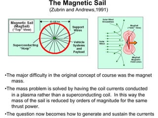
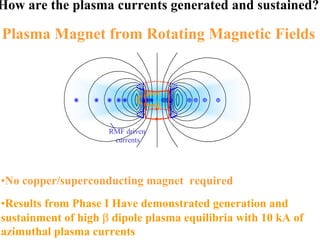

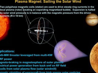
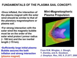
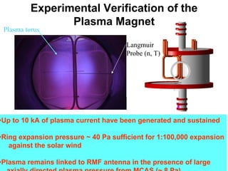

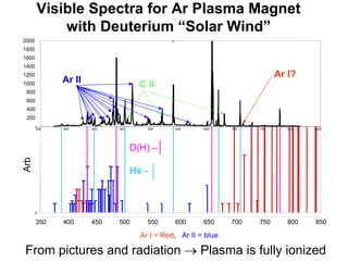
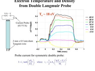
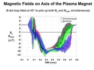
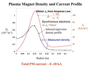
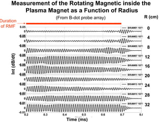
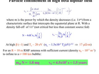
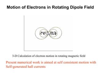
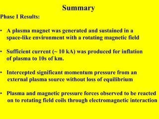

The document summarizes research on a proposed plasma magnet propulsion concept. Key points: 1) Experiments at the University of Washington generated and sustained up to 10kA of plasma current using a rotating magnetic field, enough to inflate a plasma bubble similar to a mini-magnetosphere. 2) Measurements found electron temperatures of 18eV and densities sufficient to sustain particle confinement for over a year within an inflated 100km plasma bubble. 3) Numerical simulations modeled self-consistent electron motion within experimental rotating dipole fields and plasma inflation dynamics, supporting the feasibility of the plasma magnet concept for deep space exploration propulsion.


![1012 winglee[1]](https://cdn.slidesharecdn.com/ss_thumbnails/d6vlpyl4seylo9svznet-signature-3e49a9720aafd161ec5213fc5cb0fac76e0a38578f2089fb876ad1cc6de4bad4-poli-140825181335-phpapp01-thumbnail.jpg?width=640&height=640&fit=bounds)


![Wassersug richard[1]](https://cdn.slidesharecdn.com/ss_thumbnails/wassersugrichard1-140914105156-phpapp02-thumbnail.jpg?width=640&height=640&fit=bounds)


