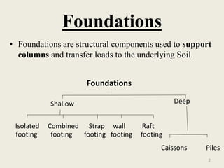
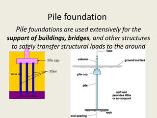
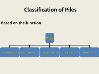
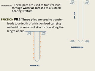
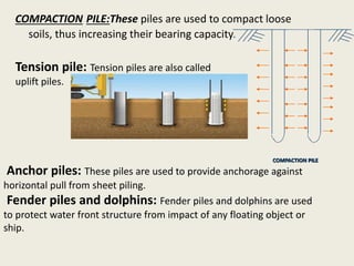
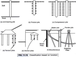
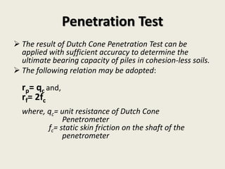
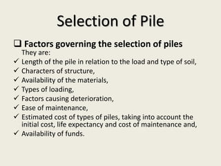
Pile foundation
By-abid khan
(b.tech civil 3rd sem)
Amity School of Engineering & Technology
Summited by—
mohan khantariya
Foundations
• Foundations are structural components used to support
columns and transfer loads to the underlying Soil.
2
Foundations
Isolated Combined Strap wall Raft
Shallow
footing footing footing footing footing
Caissons Piles
Deep
Pile foundation
Pile foundations are used extensively for the
support of buildings, bridges, and other structures
to safely transfer structural loads to the ground
Pile cap
Piles
Weak soil
Bearing stratum
Pile foundations are used in the
following situations:
1.where the soil is compressible,
2.where the soil is water logged
3.The top soil has poor bearing capacity
4.The subsoil water level is high
The major uses of piles:
To carry vertical compression loads,
To resist uplift loads
To resist horizontal or inclined loads
Classification of Piles
PILES
END BEARING PILES FRICTION PILES ANCHOR PILESTENSION PILESCOMPACTION PILES
Based on the function
END BEARING PILE : These piles are used to transfer load
through water or soft soil to a suitable
bearing stratum.
END BEARING PILE
SOFTSOIL
FRICTION PILE:These piles are used to transfer
loads to a depth of a friction load carrying
material by means of skin friction along the
length of pile.
FRICTION PILE
COMPACTION PILE
COMPACTION PILE:These piles are used to compact loose
soils, thus increasing their bearing capacity.
Tension pile: Tension piles are also called
uplift piles.
Anchor piles: These piles are used to provide anchorage against
horizontal pull from sheet piling.
Fender piles and dolphins: Fender piles and dolphins are used
to protect water front structure from impact of any floating object or
ship.
CLASSIFICATION OF PILES
BASED ON FUNCTION
Based on the material & composition;
a. Concrete Pile
b. steel pile
c. timber pile
d. Composite piles
• Pre-cast Piles: Usual length: 10 m – 45 m
Usual Load: 7500 kN – 8500 kN „
• Cast-in-situ Piles:
Usual length: 5 m – 15 m
Usual Load: 200 kN – 500 kN
•„Advantage:
Relatively cheap It can be easily combined with concrete
superstructure Corrosion resistant It can bear hard driving
•„Disadvantage: Difficult to transport Difficult to achieve
desired cutoff
Concrete Pile
steel pile
• „Usual length: 15 m – 60 m „
• Usual Load: 300 kN – 1200 kN
• „Advantage: Relatively less hassle during
installation and easy to achieve cutoff level,High
driving force may be used for fast installation,
Good to penetrate hard, strata Load carrying
capacity is high
• „Disadvantage: Relatively expensive Noise
pollution during installation Corrosion Bend in
piles while driving
Timber pile
Timber piles are made from tree trunks. These piles are
available in length between 4 to 6 m. timber piles are used
where good bearing stratum is available at a relatively
shallow depth.
Composite piles
A pile which is made up of two materials like concrete and
timber or concrete and steel is called composite pile.
1. DRIVEN PILE
2. Bored piles
3.DRIVEN
AND CAST- IN- SITU PILE
Based on the method of
installation;
(i) Bored piles:
Bored piles are constructed in pre-bored holes either using a
casing or by circulating stabilizing agent like betonies slurry.
Board piles are of following types:
Small diameter piles-up to 600 mm diameter; large diameter
piles-diameter greater than 600 mm; under reamed piles.
(ii) Driven piles:
Driven piles may be of concrete, steel or timber. These piles
are driven into the soil by the impact of hammer.
(iii) Driven and cast-in-situ piles:
It is a type of driven pile. They are constructed by driving a
steel casing in to the ground. The hole is then filled with
concrete by placing the reinforcement and the casing is
gradually fted.
 Proposed by A.M. Wellington in the following general
form;
Qa=
WH
F(S+C)
Where, Qa= allowable load
W= wt. of the hammer
H= height of the fall
F= F.O.S, taken as “6”
S= final set (penetration)
C= empirical constant
2.5 for drop hammer,&
0.25 for single and double acting
hammers.
Engineering News formula:
IS: 2911 gives the following formula based on the original
expression of Hiley:
Qd=
𝜼 𝒉WH 𝜼 𝒃
𝑺+𝑪/𝟐
Where, Qd= ultimate load on a pile
C= toatal elastic compression
C = C1+C2+C3, temporary elastic compression of dolly
and packing, pile & soil respectively.
𝜼 𝒉 = efficiency of hammer
𝜼 𝒃=efficiency of hammer blow (i.e. ratio
of energy after impact to striking energy
of ram)
Hiley’s formula:
 Ultimate bearing capacity of a pile is determined by the formula
given below;
Qd= Rf + Rp= Asrf + Aprp
Where, Rf = total ultimate skin friction
Rp= total ultimate point or end bearing
resistance
As= surface area of pile upon which the
skin friction acts
Ap= area of cross section of pile on which
bearing resistance acts
rf = average skin friction
rp= unit point or toe resistance
 A FOS 2.5 or 3 may be adopted for finding the allowable
load.
Static formula
 The result of Dutch Cone Penetration Test can be
applied with sufficient accuracy to determine the
ultimate bearing capacity of piles in cohesion-less soils.
 The following relation may be adopted:
rp= qc and,
rf= 2fc
where, qc= unit resistance of Dutch Cone
Penetrometer
fc= static skin friction on the shaft of the
penetrometer
Penetration Test
 Factors governing the selection of piles
They are:
 Length of the pile in relation to the load and type of soil,
 Characters of structure,
 Availability of the materials,
 Types of loading,
 Factors causing deterioration,
 Ease of maintenance,
 Estimated cost of types of piles, taking into account the
initial cost, life expectancy and cost of maintenance and,
 Availability of funds.
Selection of Pile
HTTP://WWW.UNDERSTANDCONSTRUCTION.CO
M/TYPES-OF-FOUNDATIONS.HTML
HTTP://WWW.IITK.AC.IN/NICEE/WCEE/ARTICLE/
11_2081.PDF
HTTP://DANBROWNANDASSOCIATES.COM/GIDF
C/ARCHIVES/343
WWW.FHWA.DOT.GOV/PUBLICATIONS/RESEARC
H/INFRASTRUCTURE/GEOTECHNICAL/05159/05
159.PDF
Referance
Pile foundation

Pile foundation

  • 1.
    Pile foundation By-abid khan (b.techcivil 3rd sem) Amity School of Engineering & Technology Summited by— mohan khantariya
  • 2.
    Foundations • Foundations arestructural components used to support columns and transfer loads to the underlying Soil. 2 Foundations Isolated Combined Strap wall Raft Shallow footing footing footing footing footing Caissons Piles Deep
  • 3.
    Pile foundation Pile foundationsare used extensively for the support of buildings, bridges, and other structures to safely transfer structural loads to the ground Pile cap Piles Weak soil Bearing stratum
  • 4.
    Pile foundations areused in the following situations: 1.where the soil is compressible, 2.where the soil is water logged 3.The top soil has poor bearing capacity 4.The subsoil water level is high The major uses of piles: To carry vertical compression loads, To resist uplift loads To resist horizontal or inclined loads
  • 5.
    Classification of Piles PILES ENDBEARING PILES FRICTION PILES ANCHOR PILESTENSION PILESCOMPACTION PILES Based on the function
  • 6.
    END BEARING PILE: These piles are used to transfer load through water or soft soil to a suitable bearing stratum. END BEARING PILE SOFTSOIL FRICTION PILE:These piles are used to transfer loads to a depth of a friction load carrying material by means of skin friction along the length of pile. FRICTION PILE
  • 7.
    COMPACTION PILE COMPACTION PILE:Thesepiles are used to compact loose soils, thus increasing their bearing capacity. Tension pile: Tension piles are also called uplift piles. Anchor piles: These piles are used to provide anchorage against horizontal pull from sheet piling. Fender piles and dolphins: Fender piles and dolphins are used to protect water front structure from impact of any floating object or ship.
  • 9.
    CLASSIFICATION OF PILES BASEDON FUNCTION Based on the material & composition; a. Concrete Pile b. steel pile c. timber pile d. Composite piles
  • 10.
    • Pre-cast Piles:Usual length: 10 m – 45 m Usual Load: 7500 kN – 8500 kN „ • Cast-in-situ Piles: Usual length: 5 m – 15 m Usual Load: 200 kN – 500 kN •„Advantage: Relatively cheap It can be easily combined with concrete superstructure Corrosion resistant It can bear hard driving •„Disadvantage: Difficult to transport Difficult to achieve desired cutoff Concrete Pile
  • 11.
    steel pile • „Usuallength: 15 m – 60 m „ • Usual Load: 300 kN – 1200 kN • „Advantage: Relatively less hassle during installation and easy to achieve cutoff level,High driving force may be used for fast installation, Good to penetrate hard, strata Load carrying capacity is high • „Disadvantage: Relatively expensive Noise pollution during installation Corrosion Bend in piles while driving
  • 12.
    Timber pile Timber pilesare made from tree trunks. These piles are available in length between 4 to 6 m. timber piles are used where good bearing stratum is available at a relatively shallow depth. Composite piles A pile which is made up of two materials like concrete and timber or concrete and steel is called composite pile.
  • 13.
    1. DRIVEN PILE 2.Bored piles 3.DRIVEN AND CAST- IN- SITU PILE Based on the method of installation;
  • 14.
    (i) Bored piles: Boredpiles are constructed in pre-bored holes either using a casing or by circulating stabilizing agent like betonies slurry. Board piles are of following types: Small diameter piles-up to 600 mm diameter; large diameter piles-diameter greater than 600 mm; under reamed piles. (ii) Driven piles: Driven piles may be of concrete, steel or timber. These piles are driven into the soil by the impact of hammer. (iii) Driven and cast-in-situ piles: It is a type of driven pile. They are constructed by driving a steel casing in to the ground. The hole is then filled with concrete by placing the reinforcement and the casing is gradually fted.
  • 15.
     Proposed byA.M. Wellington in the following general form; Qa= WH F(S+C) Where, Qa= allowable load W= wt. of the hammer H= height of the fall F= F.O.S, taken as “6” S= final set (penetration) C= empirical constant 2.5 for drop hammer,& 0.25 for single and double acting hammers. Engineering News formula:
  • 16.
    IS: 2911 givesthe following formula based on the original expression of Hiley: Qd= 𝜼 𝒉WH 𝜼 𝒃 𝑺+𝑪/𝟐 Where, Qd= ultimate load on a pile C= toatal elastic compression C = C1+C2+C3, temporary elastic compression of dolly and packing, pile & soil respectively. 𝜼 𝒉 = efficiency of hammer 𝜼 𝒃=efficiency of hammer blow (i.e. ratio of energy after impact to striking energy of ram) Hiley’s formula:
  • 17.
     Ultimate bearingcapacity of a pile is determined by the formula given below; Qd= Rf + Rp= Asrf + Aprp Where, Rf = total ultimate skin friction Rp= total ultimate point or end bearing resistance As= surface area of pile upon which the skin friction acts Ap= area of cross section of pile on which bearing resistance acts rf = average skin friction rp= unit point or toe resistance  A FOS 2.5 or 3 may be adopted for finding the allowable load. Static formula
  • 18.
     The resultof Dutch Cone Penetration Test can be applied with sufficient accuracy to determine the ultimate bearing capacity of piles in cohesion-less soils.  The following relation may be adopted: rp= qc and, rf= 2fc where, qc= unit resistance of Dutch Cone Penetrometer fc= static skin friction on the shaft of the penetrometer Penetration Test
  • 19.
     Factors governingthe selection of piles They are:  Length of the pile in relation to the load and type of soil,  Characters of structure,  Availability of the materials,  Types of loading,  Factors causing deterioration,  Ease of maintenance,  Estimated cost of types of piles, taking into account the initial cost, life expectancy and cost of maintenance and,  Availability of funds. Selection of Pile
  • 20.