Downloaded 2,356 times
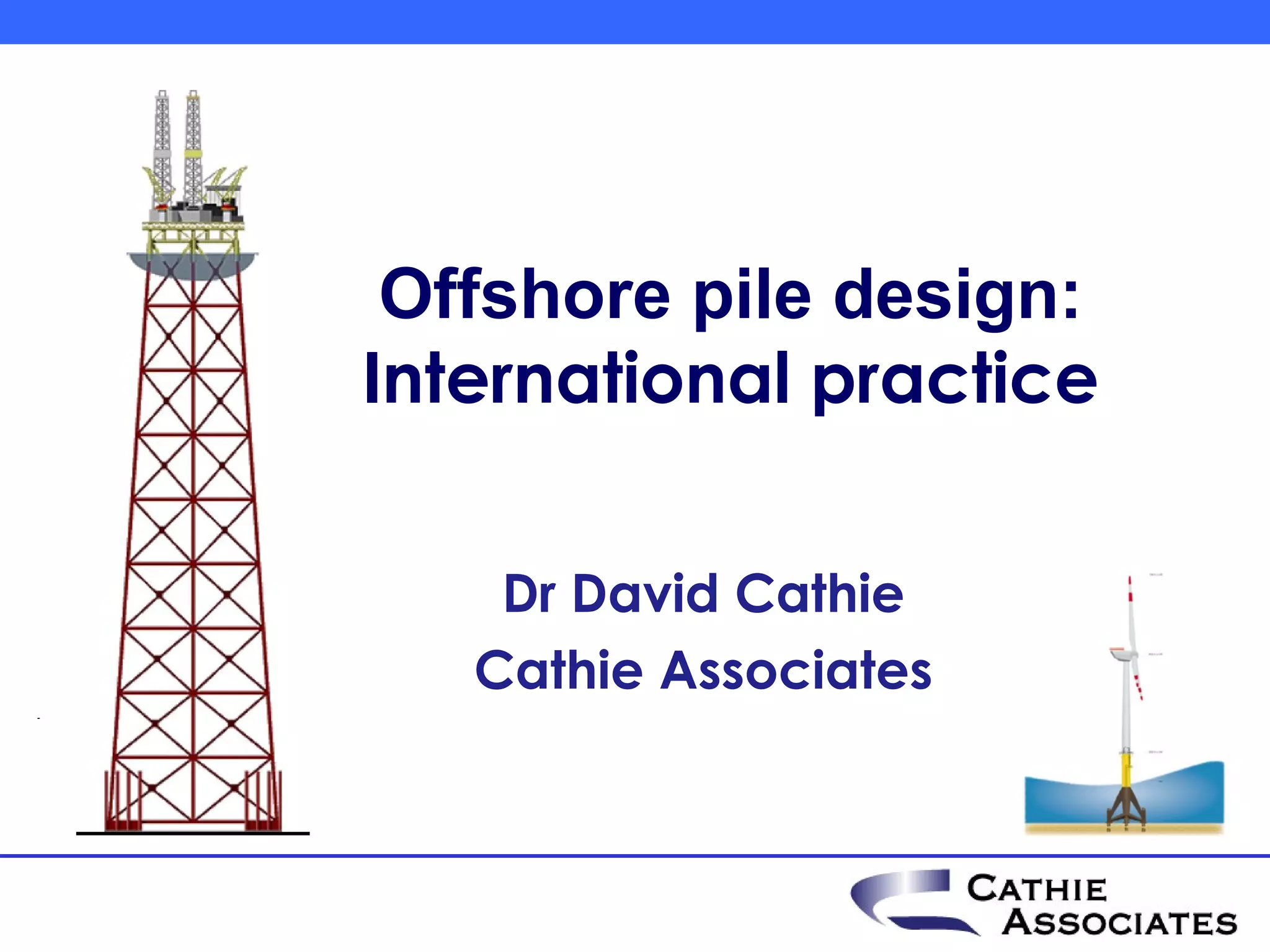


![CPT method – application by Shell
Dynamic SRD [MN] Dynamic SRD [MN]
0 4 8 12 16 20 0 4 8 12 16
0 0
5 ICP
API
20
10
15
40
20
25 ICP
60 API
m
m
w
w
a
a
o
e
o
e
n
n
B
B
P
P
S
S
]
[
r
]
[
r
t
t
f
f
l
i
l
i
30
35 80
Overy (2007) The Use of ICP Design Methods for the
Foundations of Nine Platforms installed in the UK North Sea, Int.
Offshore Site Investigation and Geotechnics Conference
Offshore pile design : International practice](https://image.slidesharecdn.com/piledesignaccordingtointernationalpractice06-121016084206-phpapp01/75/Offshore-pile-design-according-to-international-practice-14-2048.jpg)


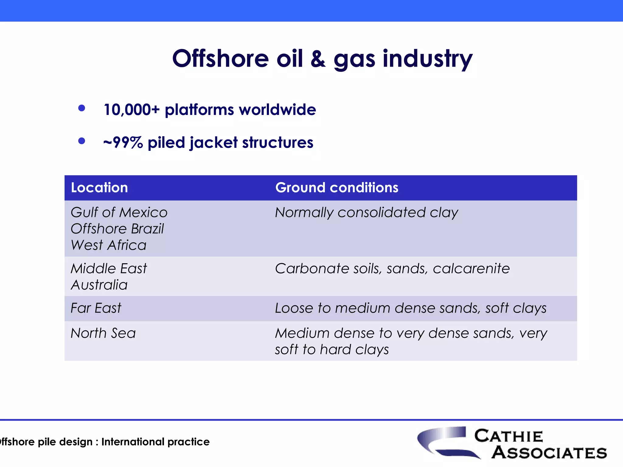
![Pile driving monitoring – signal matching
G-OCTOPUS
C126 UW PDM OLOWI PILE DRIVING ANALYZER ®
PDA OP: ACR-MHA Version 2009.098.061
PILE C1
JACKET WHT-A
BN 3/828
30/07/2009 18:23:25
80000 Signal matching (CAPWAP/TNOWAVE)
7.16 EMX 845.1 kN-m
kN m/s E2E 828.6 kN-m
CSI 229.6 MPa
F Iteratively modifying V numerical soil model until the
a EF2 848.7 kN-m
E2F 843.1 kN-m
calculated reflective wave matches the measured waveEV2 877.5 kN-m
RMX 18448 kN
DMX 30.3 mm
DFN 14.0 mm
B w o 12
lo N. 63
8 0 .0
00 kN
LE 39.970 m
AR 2759.57 cm^2 W pM
u sd
W pCt
u p
EM 207413 MPa
51.2ms SP 77.5 kN/m3
15.60 ms WS 5123.0 m/s
Measured upward and 2 6 .7
66 EA/C 11173 kN-s/m
80000 downward waves 80000
15
LP 25.750 m
45 ms
kN kN
F12 A2 6 L/c
WD WU
- 6 67
26 .
F1: [898W] 132.7 (1)
F2: [904W] 130.2 (1)
A2: [29997] 1035 g's/v (1) Measured and
calculated
upward waves
- 0 00
80 .
51.2ms
Offshore pile design : International practice](https://image.slidesharecdn.com/piledesignaccordingtointernationalpractice06-121016084206-phpapp01/75/Offshore-pile-design-according-to-international-practice-23-2048.jpg)


![Tripod and monopile loads
Bending moment at mudlevel during 50 year severe sea state
350000
Tripod Pile Monopile
300000
250000
200000
150000
100000
50000
0
-50000 0 20 40 60 80 100 120 140
M
m
N
o
n
b
e
k
s
-100000
r
t
]
[
-150000
-200000
time [s]
Axial (vertical) force at mudlevel during 50 year severe sea state
10000
Monopile Tripod Pile max compression Tripod max tension
5000
0
0 20 40 60 80 100 120 140
-5000
-10000
-15000
M
m
N
o
b
e
k
c
s
-20000
r
]
[
f
-25000
-30000
time [s]
Offshore pile design : International practice](https://image.slidesharecdn.com/piledesignaccordingtointernationalpractice06-121016084206-phpapp01/75/Offshore-pile-design-according-to-international-practice-28-2048.jpg)


The document outlines international practices in offshore pile design within the oil and gas industry, emphasizing the extensive experience and safety measures for both small and large projects. It discusses various standards and methods for pile resistance, driveability, and monitoring, while also addressing innovations and reliability of designs in the context of risk aversion. The insights on tripod structures highlight key design issues, showing their advantages over monopiles, and stress the importance of adopting practical solutions based on existing industry experience.


![Grl report #103067 grlweap - lpv 16[1].2](https://cdn.slidesharecdn.com/ss_thumbnails/grlreport103067-grlweap-lpv161-2-120518090804-phpapp01-thumbnail.jpg?width=640&height=640&fit=bounds)


