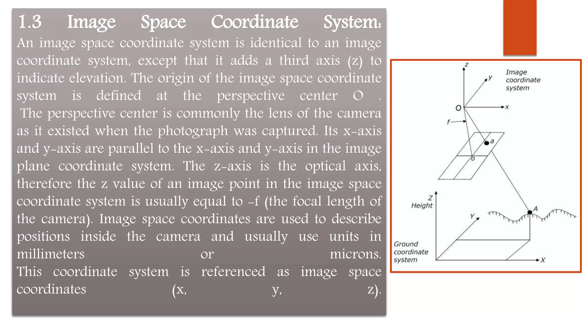
1) The document discusses various coordinate systems used in photogrammetry including pixel, image, image space, and ground coordinate systems.
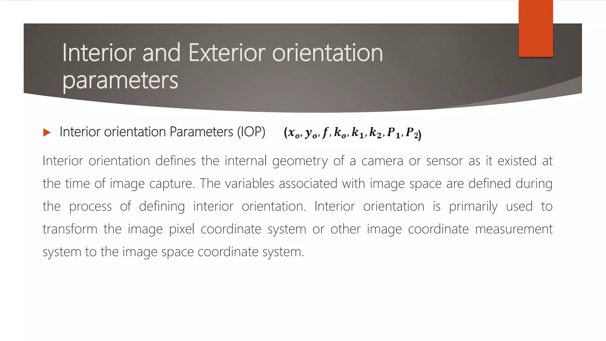
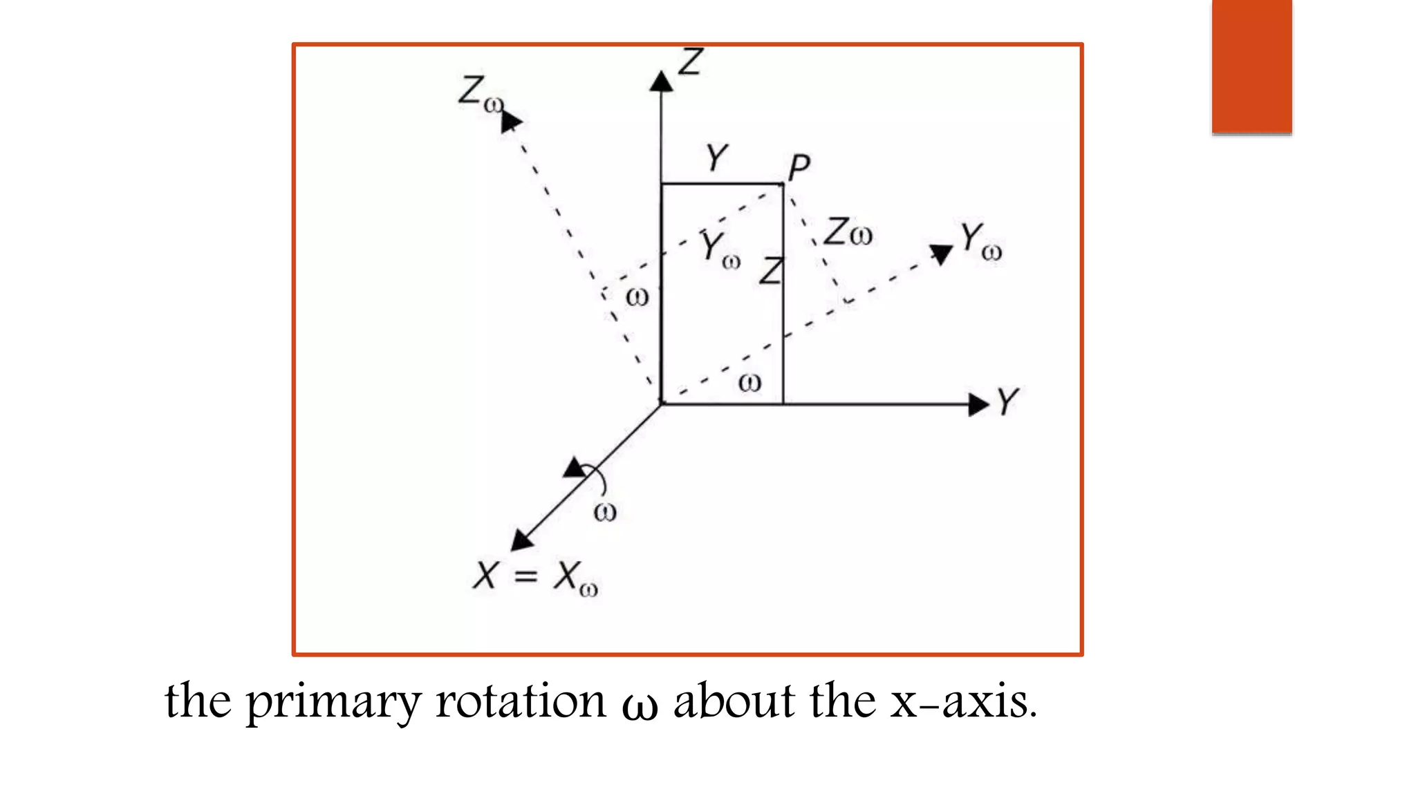
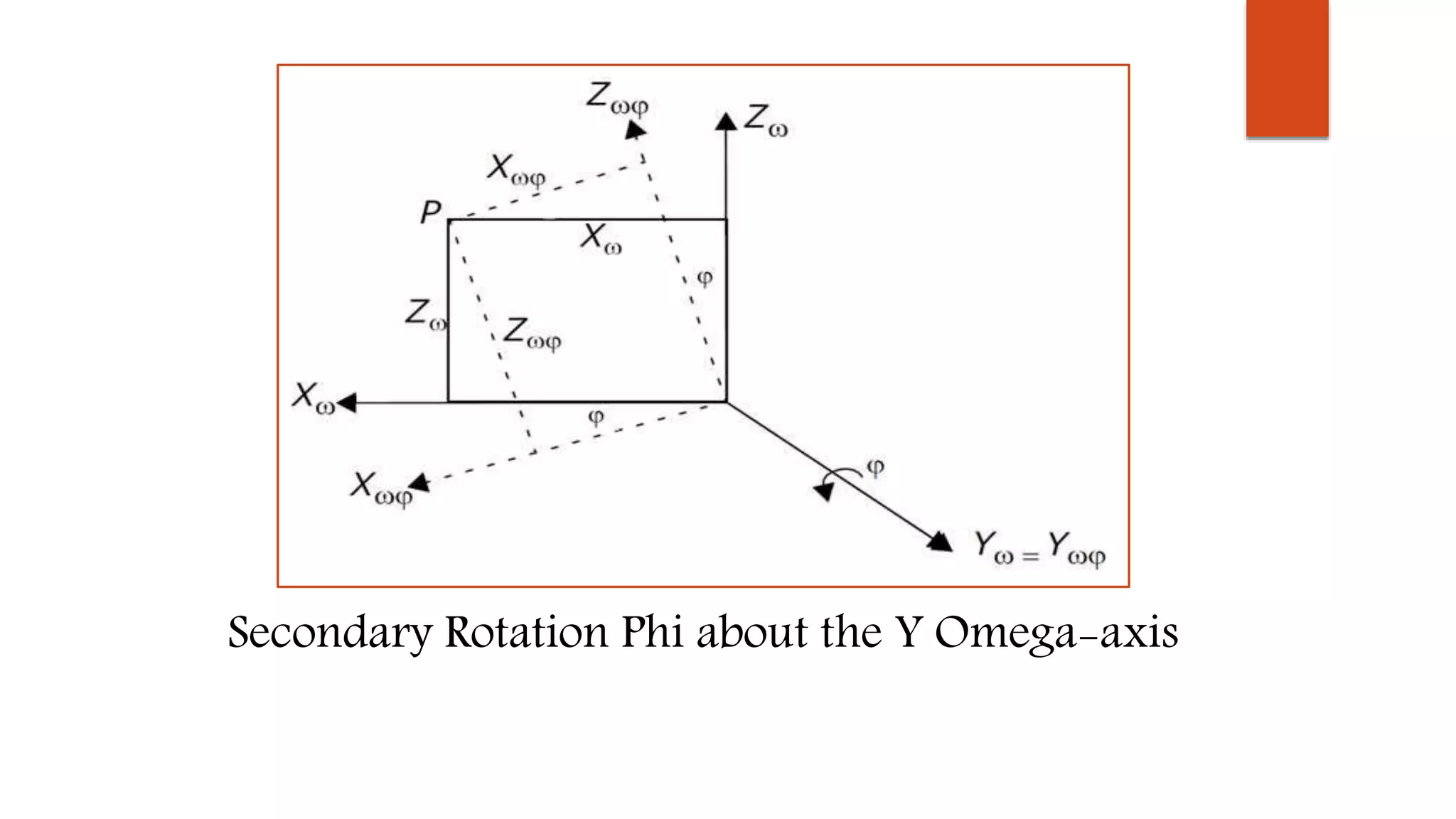
2) It also covers topics like interior orientation parameters (principal point, focal length), exterior orientation parameters (position and rotation angles), and two-dimensional coordinate transformations.
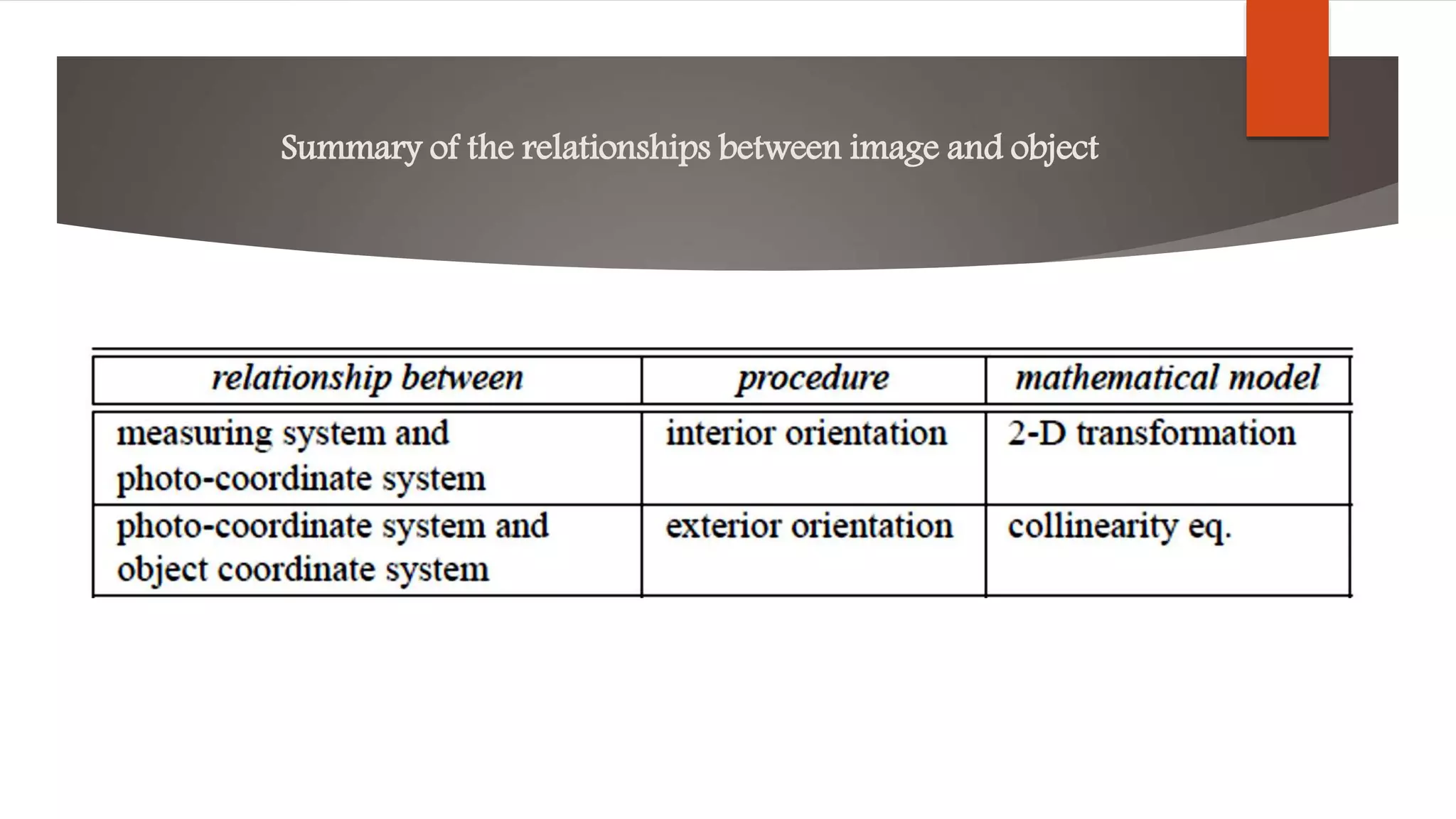
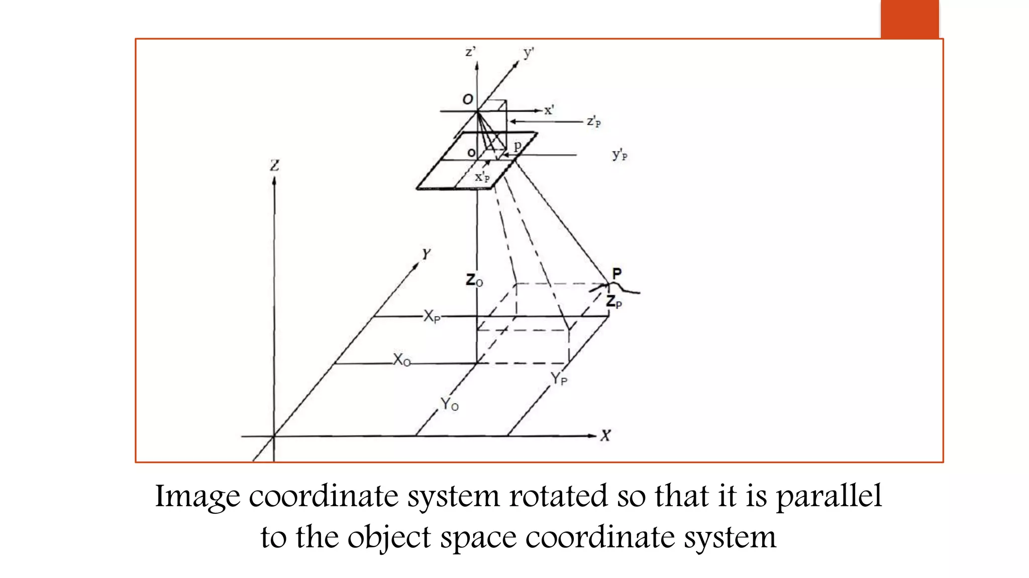
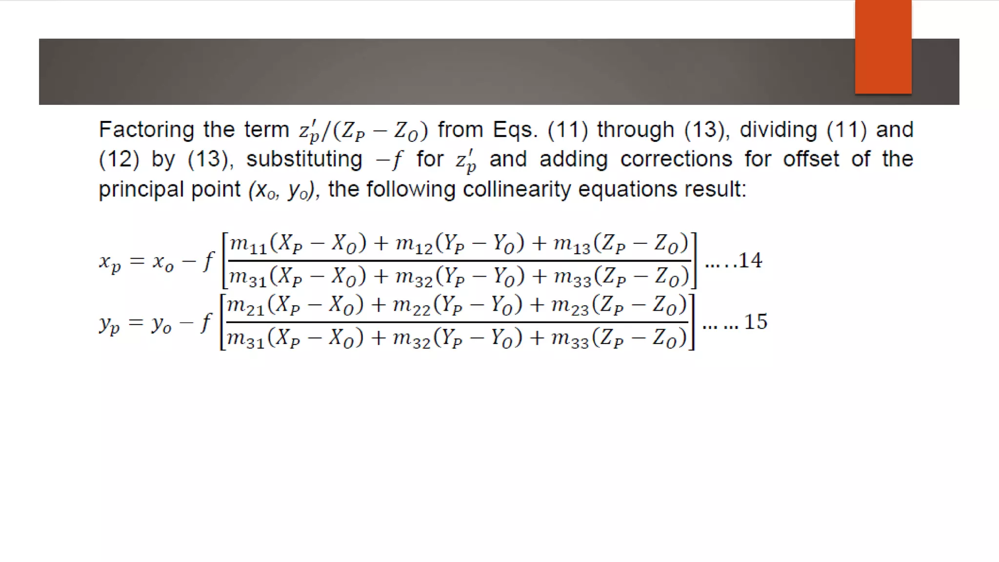
3) The relationships between the image, camera, and ground coordinates are defined using these parameters and coordinate systems to allow for mapping between the three domains.