Downloaded 262 times
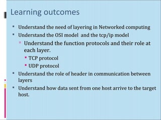
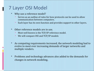
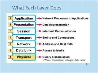
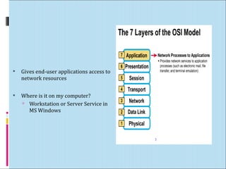
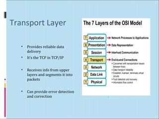
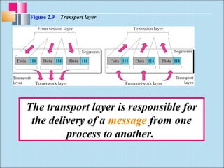
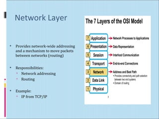
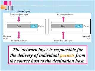
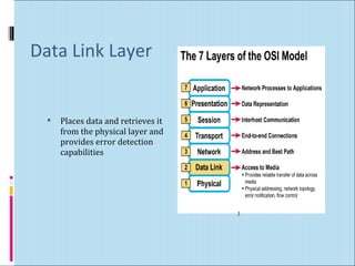
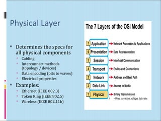
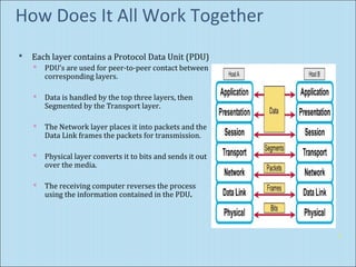
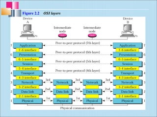
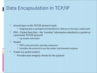
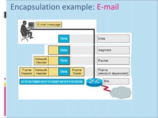
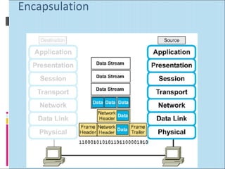
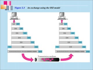
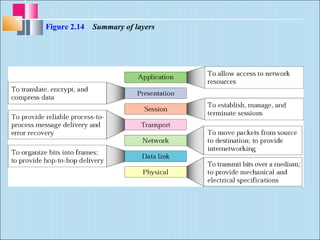
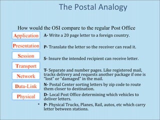
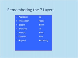
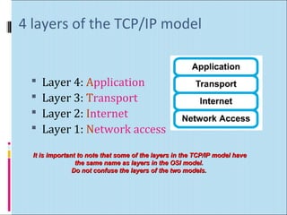
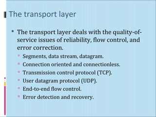
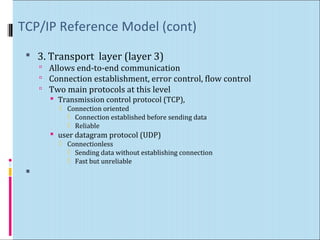
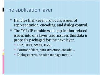
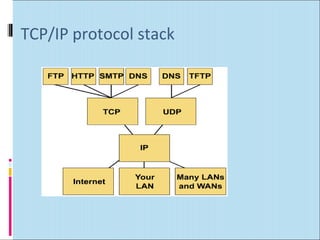
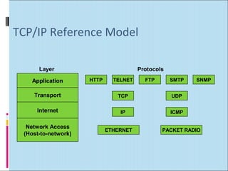
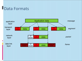
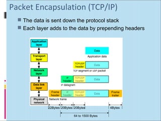
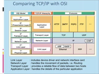

This document discusses layered network models, specifically the OSI model and TCP/IP model. It provides an overview of each layer in both models and their functions. The key points are: - The OSI model defines 7 layers that break communication into smaller parts to simplify the process and allow different hardware/software to work together. - The TCP/IP model has 4 layers - application, transport, internet, and network access. It is used widely on the internet. - Each layer adds header information to data as it moves down the stack. This encapsulation allows communication between layers and across networks.


![[kmasecutity.net] - Mô hình 7 tầng osi](https://cdn.slidesharecdn.com/ss_thumbnails/mhnh7tngosi-130312031740-phpapp01-thumbnail.jpg?width=640&height=640&fit=bounds)