The document compares the OSI and TCP/IP models and provides details on each layer of the OSI model.
The key points are:
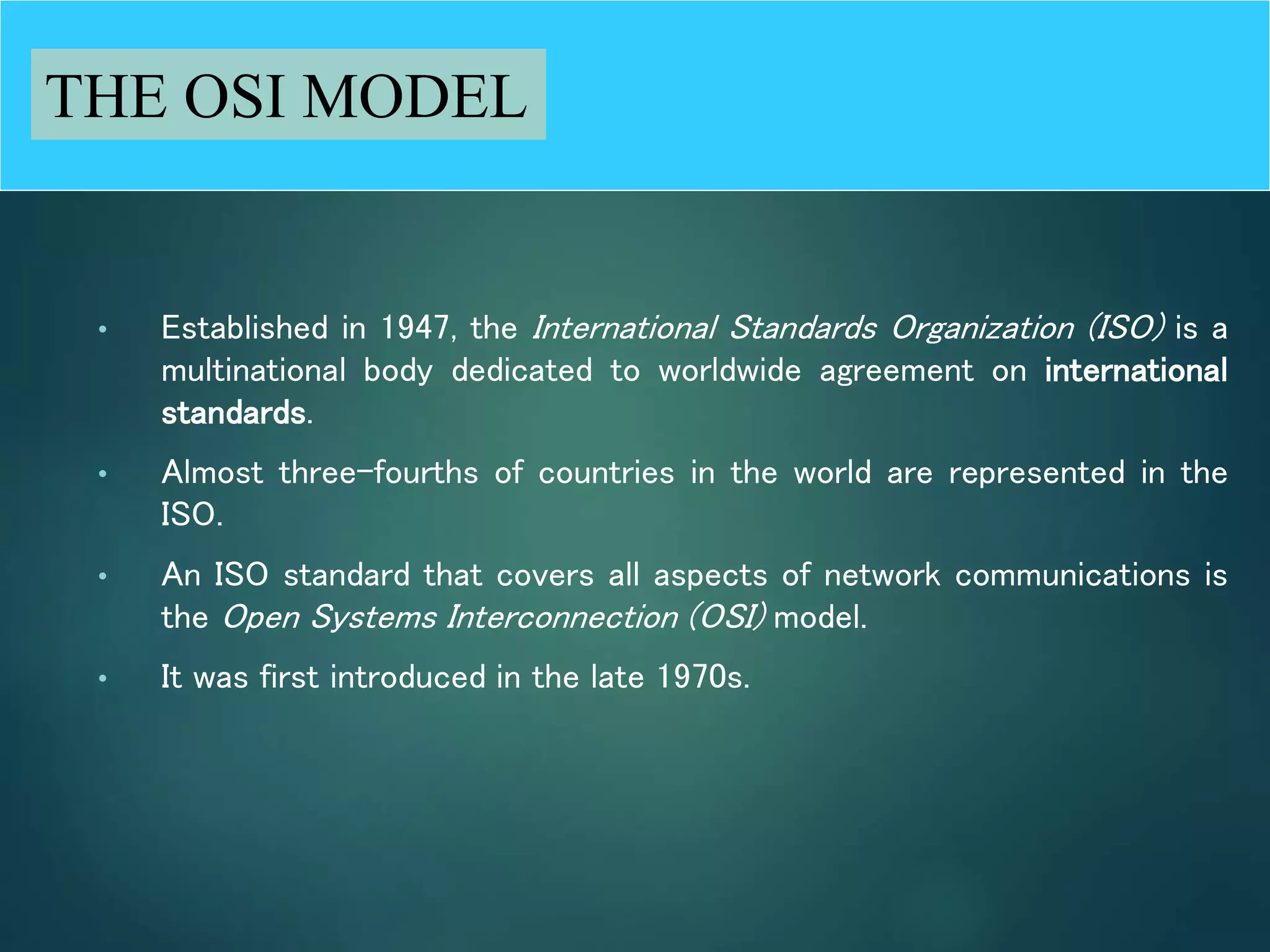
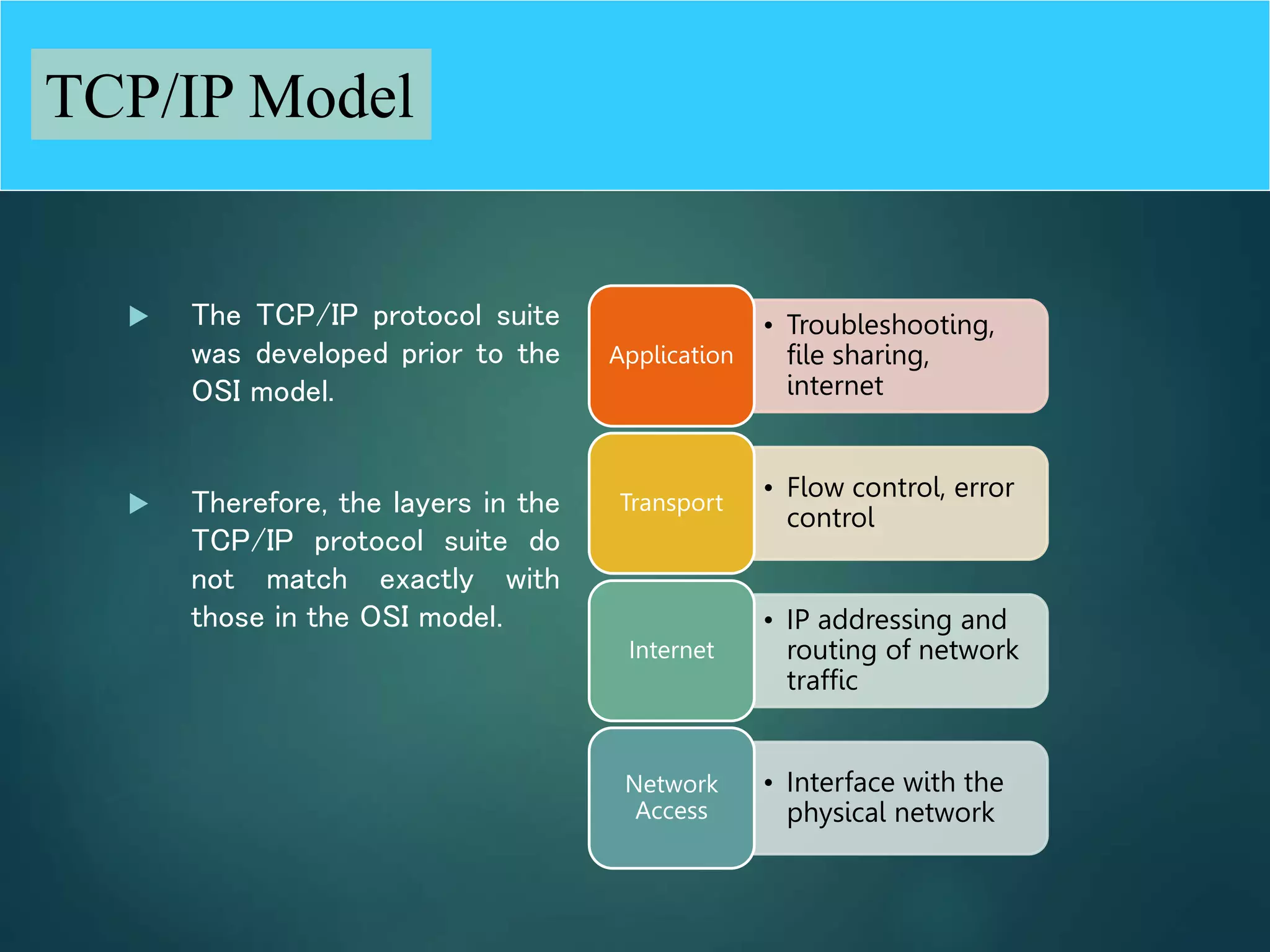
1) The OSI model is an internationally standardized network architecture consisting of 7 layers, while TCP/IP was developed independently and its layers do not exactly match the OSI layers.
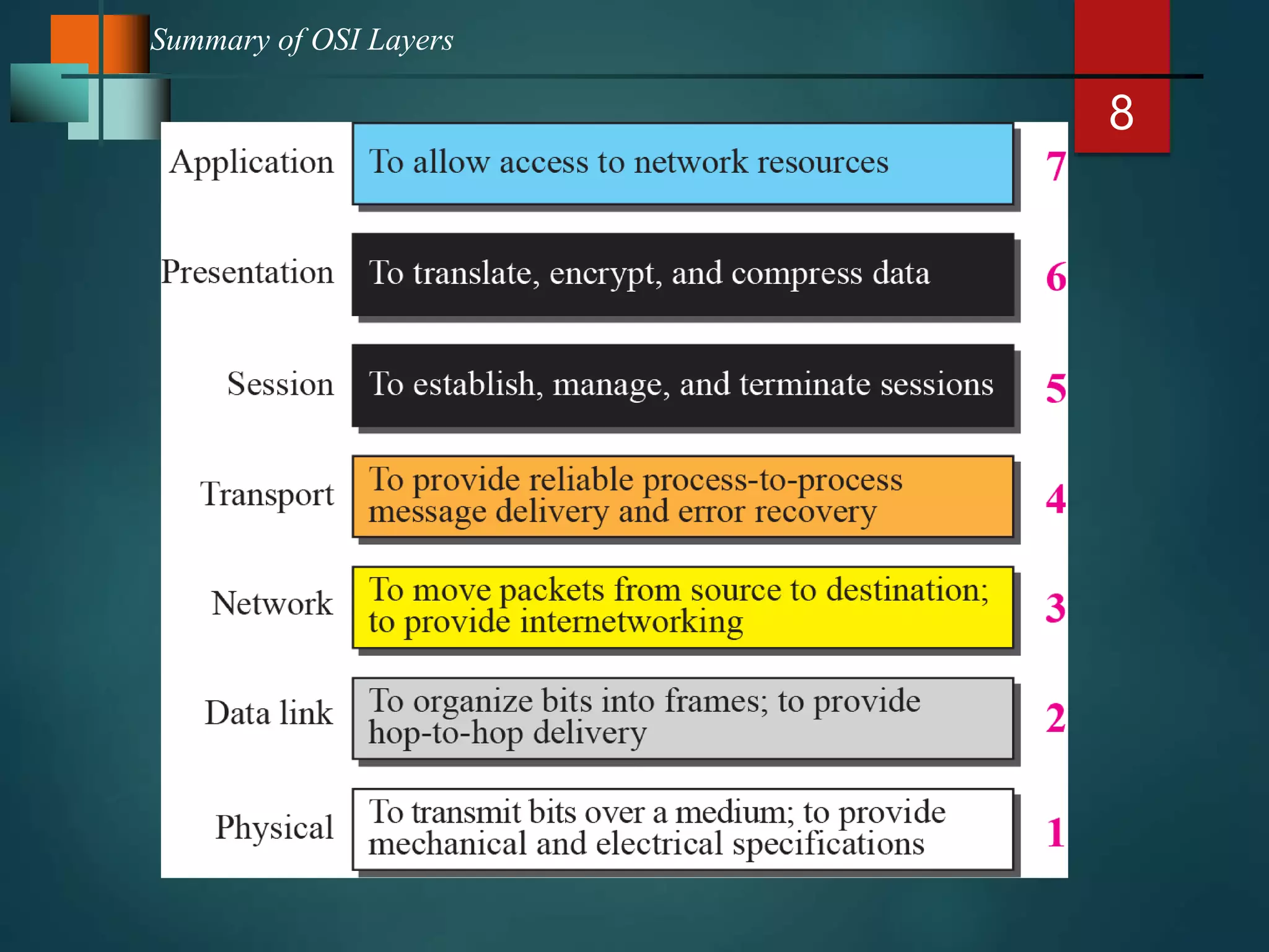
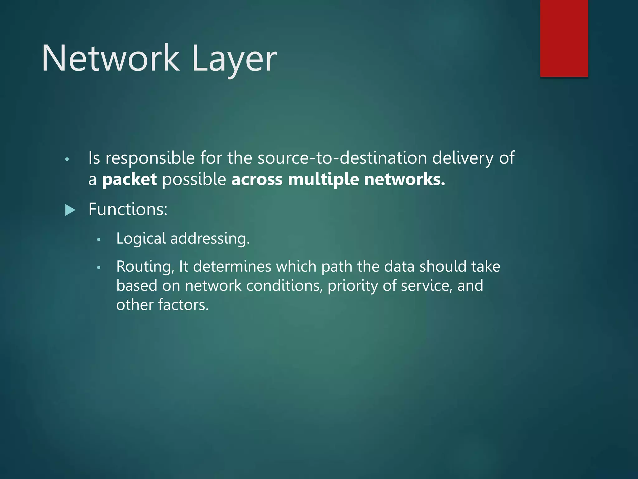
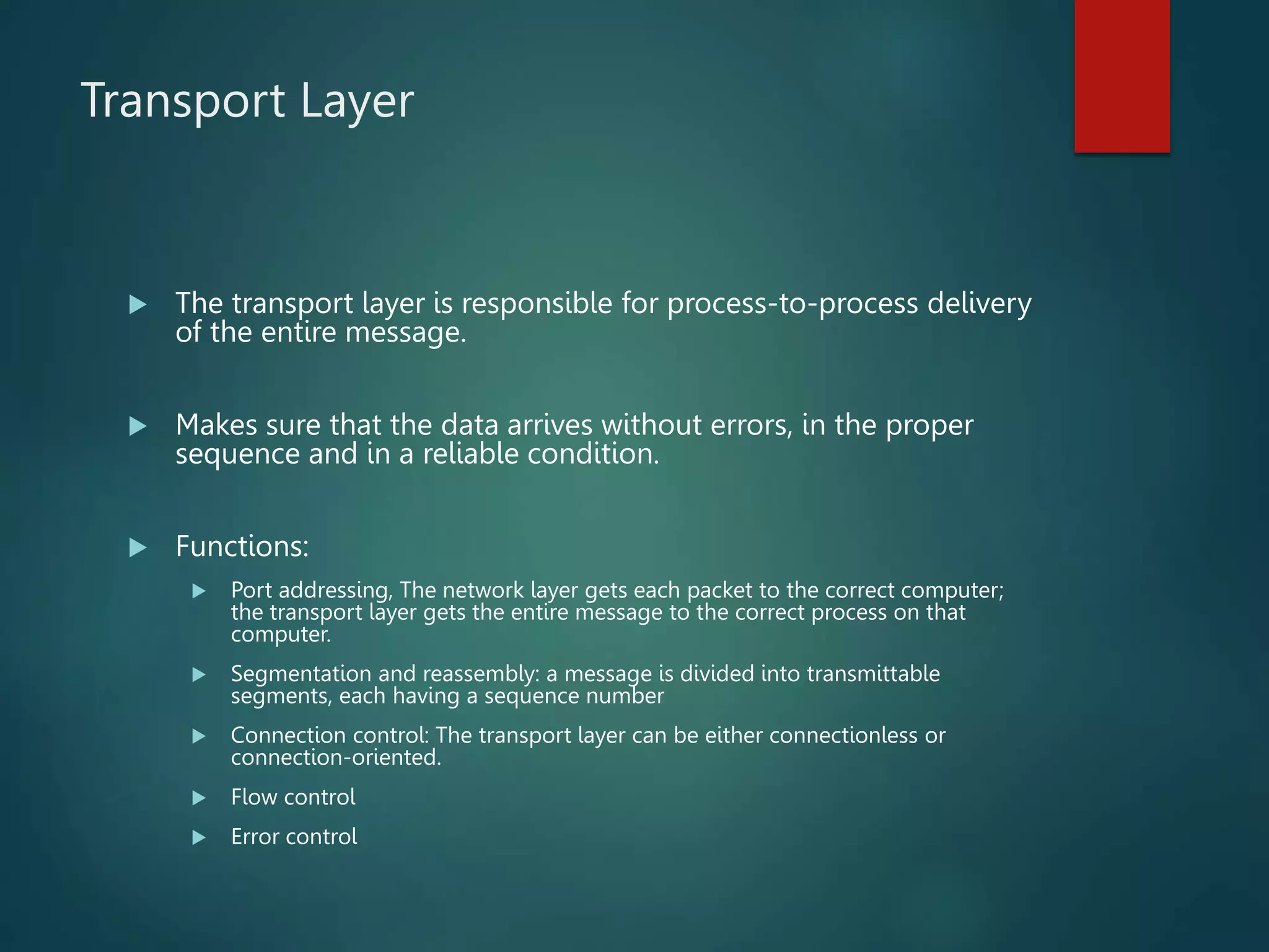
2) Each OSI layer has a specific function, with the physical layer defining physical interfaces, the data link layer handling framing and addressing, the network layer routing packets, and higher layers focusing on reliability and delivering data to applications.
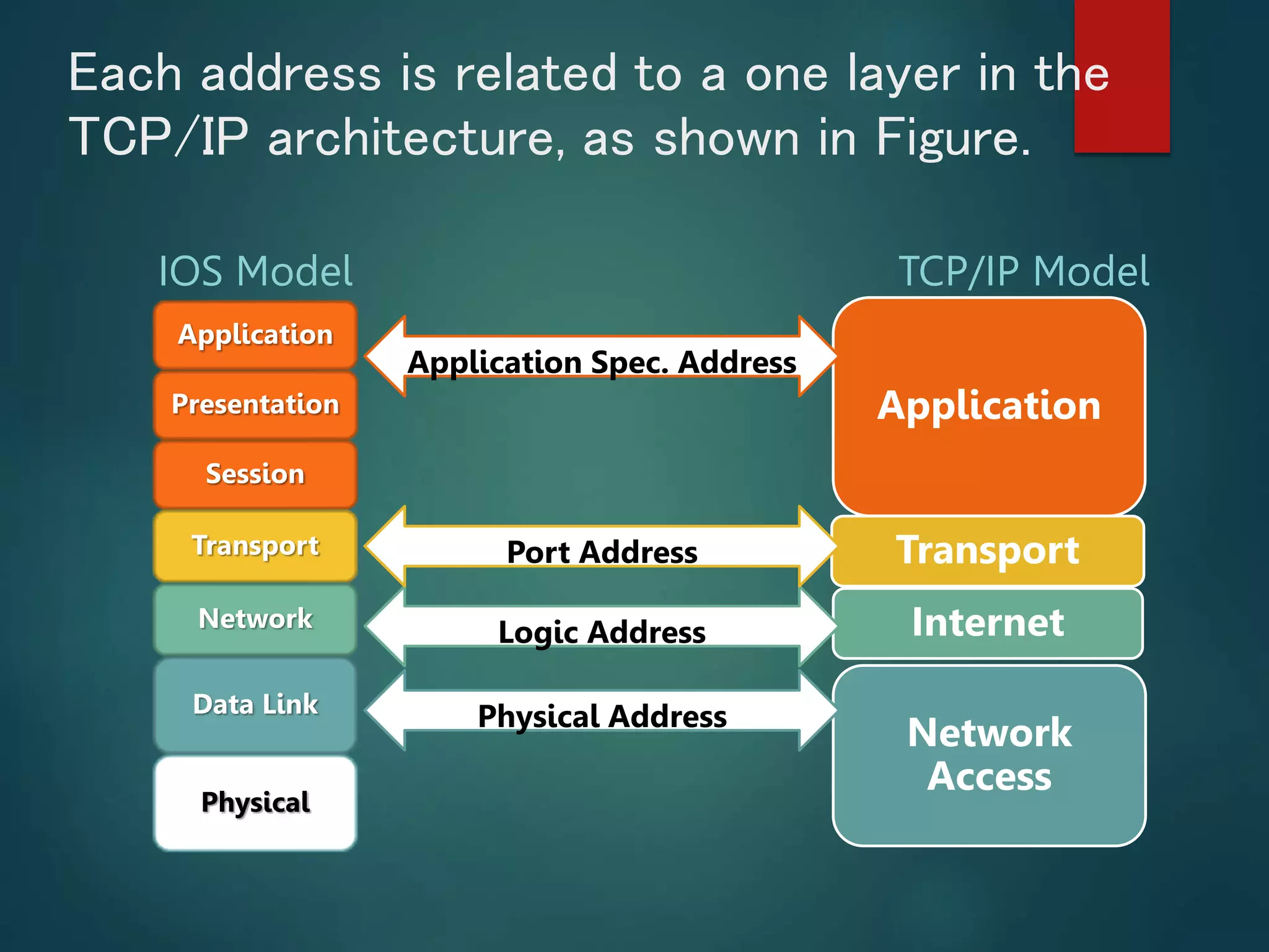
3) TCP/IP uses four types of addresses - physical, logical, port, and application-specific - that correspond to different layers, with physical addresses changing