Downloaded 234 times
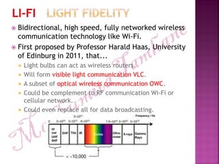


Li-Fi is a high-speed, bidirectional wireless communication technology using visible light for data transmission, proposed by Professor Harald Haas in 2011. It is significantly faster than Wi-Fi, capable of speeds exceeding 224 Gbps, while being more energy-efficient and secure due to its inability to penetrate walls. Li-Fi has applications in sensitive areas such as hospitals and airlines, providing safer and more reliable connectivity compared to traditional radio frequency communications.