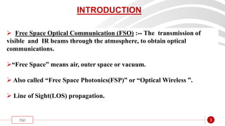
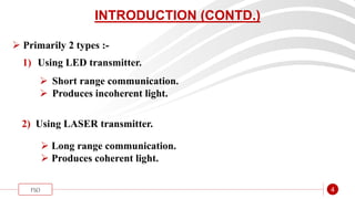
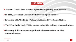
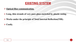
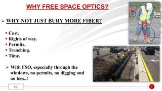
FREE SPACE
OPTICAL
COMMUNICATION
B Y
JOSH WA V SU N N Y
R EG N O: VIT16C S021
SEMIN A R GU ID E:
ASST. PROF. VIMAL BABU P
C SE D EPA R TMEN T
1
Introduction
History
Existing System
Why Free Space Optics?
System Overview
Challenges
Advantages
Disadvantages
Applications
Conclusion
References
2
“
FSO 3
INTRODUCTION
 Free Space Optical Communication (FSO) :-- The transmission of
visible and IR beams through the atmosphere, to obtain optical
communications.
“Free Space” means air, outer space or vacuum.
 Also called “Free Space Photonics(FSP)” or “Optical Wireless ”.
 Line of Sight(LOS) propagation.
“
FSO 4
INTRODUCTION (CONTD.)
 Primarily 2 types :-
1) Using LED transmitter.
 Short range communication.
 Produces incoherent light.
2) Using LASER transmitter.
 Long range communication.
 Produces coherent light.
“
FSO 5
HISTORY
 Ancient Greeks used a coded alphabetic signalling with torches.
In 1880, Alexander Graham Bell invented “photophone”.
Invention of LASERs in 1960s revolutionized Free Space Optics.
The USA, in the early 1980s, started using it in military communications.
Germany & France made significant advancements in satellite
communications.
“
FSO 6
EXISTING SYSTEM
 Optical fiber communication.
 Long, thin strands of very pure glass encircled by plastic casing.
 Works under the principle of Total Internal Reflection(TIR).
 Costly.
“
FSO 7
WHY FREE SPACE OPTICS?
 WHY NOT JUST BURY MORE FIBER?
 Cost.
 Rights of way.
 Permits.
 Trenching.
 Time.
 With FSO, especially through the
windows, no permits, no digging and
no fees..!
“
FSO 8
WHY FREE SPACE OPTICS?(contd.)
 Very narrow and directional beam.
 Beams with very narrow diameter.
 Very close spacing of links without interference.
 No side lobes.
 Highly secure.
 Efficient use of energy.
 Ranges of 20m to about 4kms possible.
“
FSO 9
WHY FREE SPACE OPTICS?(contd.)
 Deployment behind windows.
 Rapid installations without trenching and
permitting.
 Direct connection to the end user.
 Bypasses the building owner.
“
FSO 10
WHY FREE SPACE OPTICS?(contd.)
“
FSO 11
SYSTEM OVERVIEW & WORKING
 Uses a directed beam of light radiation b/w transmitter and receiver.
 An FSO unit consists of :-
1. Optical Transmitter.
2. Optical Receiver.
3. Transmission Medium.
 Uses lens on both transmitter & receiver.
 Maximum range is about 4 kms.
“
FSO 12
SYSTEM OVERVIEW & WORKING (contd.)
A basic diagram of FSO
“
FSO 13
SYSTEM OVERVIEW & WORKING (contd.)
“
FSO 14
SYSTEM OVERVIEW & WORKING (contd.)
“
FSO 15
SYSTEM OVERVIEW & WORKING (contd.)
1) Source :- Data to be transmitted.
2) Modulator :- Performs direct modulation of message
signal with the carrier signal.
3) Laser Driver :- A device that delivers constant current
to the laser diode for smooth operation.
4) Laser Diode :- Produces modulated laser beams for transmission.
“
FSO 16
SYSTEM OVERVIEW & WORKING (contd.)
5) Atmospheric channel :- Medium through which LASER beam
propagates.
6) Photo Detector :- Converts received light signals into electricity or
voltage.
7) Amplifier :- Amplifies the converted signal for efficient demodulation.
8) Demodulator :- Demodulates the received signal to obtain the
transmitted message.
“
FSO 17
SYSTEM OVERVIEW & WORKING (contd.)
9) Destination :- Receiving end of data which have
been transmitted.
“
FSO 18
CHALLENGES FACED
“
FSO 19
CHALLENGES FACED (contd.)
 Obstructions :- Obstructions in the path can hinder transmission.
 Fog :- Aerosol consisting of water droplets and ice.
 Absorption or scattering of optical signals due to airborne particles.
 Can result in complete outage.
 Can be alleviated by shortening link distances and adding n/w redundancies.
“
FSO 20
CHALLENGES FACED (contd.)
 Scintillation :- Heated air rising from Earth or man-made devices
creates temperature variations in the atmosphere.
 Results in beam spreading and wandering.
 Almost mutually exclusive with fog attenuation.
 Results in increased error rates, but not complete outage.
 Building sway / Seismic activity :- Movement of building can upset
receiver and transmitter alignment.
“
FSO 21
CHALLENGES FACED (contd.)
 Absorption :- Atmospheric absorption results in power attenuation
of the FSO beam.
 Scattering :- When the scatterer is smaller than the wavelength, it
is known as Rayleigh scattering. When the scatterer
is of comparable size with the wavelength, it is known
as Mie scattering.
“
FSO 22
SECURITY
 FSO laser beams cannot be detected with spectrum analyzers
or RF meters.
 FSO laser transmissions are optical and travel along a line of
sight path that cannot be intercepted easily.
 The laser beams generated by FSO systems are narrow and
invisible, making them harder to find and even harder to
intercept and crack.
“
FSO 23
ADVANTAGES
 Installation cost is very low when compared to optical fiber
communication.
 No licensing required like RF.
 Immunity from electromagnetic interference.
Deployment of FSO system is quicker and easier.
Data is highly secured.
“
FSO 24
ADVANTAGES (contd.)
 No need of trenching and digging land.
 High data transmission rate of up to 2.5GB/s.
 Unregulated spectrum and hence huge bandwidth available.
“
FSO 25
DISADVANTAGES
 Transmission rate is weather dependent.
 If sun goes directly behind the transmitter, it can intercept
the signal.
 Distance is limited.
 High launch power can cause eye hazards.
“
FSO 26
DISADVANTAGES (contd.)
 Transmission rate is affected by environmental factors
like fog, snow, rainfall et cetera.
 Atmospheric barriers and physical obstructions can act
as a deterrent.
“
FSO 27
APPLICATIONS
 Enterprise connectivity.
 It is used to communicate between spacecrafts as lower
chance of disturbances of signal.
 Military and government applications for secure data
transfer.
 Disaster management uses due to the ease in setting up
the network.
“
FSO 28
CONCLUSION
 For future short range applications, FSO provides a promising and
viable supplemental technology to wireless systems and optical fiber.
 FSO provides a low cost, rapidly deployable method of gaining access
to fiber-quality connections.
 The growing requirements for efficient and secure communications
has led to an increased interest in FSO communication.
“
FSO 29
REFERENCES
[1] S. Ghosh, K. Basu and S. K. Das, "An architecture for next generation radio access networks,"
IEEE Network, vol. 19, 20017, pp.35-42
[2] J. Hou and D. C. O'Brien, "Vertical handover-decision-making algorithm using fuzzy logic for the
integrated Radio-and-OW system," Wireless Communications, IEEE Transactions on, vol. 5, 2016, pp.
176-185.
[3] S. Ghosh. "Emergent technology based Radio Access Network (RAN) design framework for next
generation broadband wireless systems," M.S. thesis, Dept. Comp. Sci. and Eng., Univ. Texas at
Arlington, 2014.
[4] T. Kamalakis, I. Neokosmidis, A. Tsipouras, S. Pantazis and I. Andrikopoulos, "Hybrid free space
optical/millimeter wave outdoor links for broadband wireless access networks," in Personal, Indoor and
Mobile Radio Communications, IEEE 18th International Symposium on, 2018, pp. 1-5.
“
FSO 30

Free space optical communication (FSO)

  • 1.
    FREE SPACE OPTICAL COMMUNICATION B Y JOSHWA V SU N N Y R EG N O: VIT16C S021 SEMIN A R GU ID E: ASST. PROF. VIMAL BABU P C SE D EPA R TMEN T 1
  • 2.
    Introduction History Existing System Why FreeSpace Optics? System Overview Challenges Advantages Disadvantages Applications Conclusion References 2
  • 3.
    “ FSO 3 INTRODUCTION  FreeSpace Optical Communication (FSO) :-- The transmission of visible and IR beams through the atmosphere, to obtain optical communications. “Free Space” means air, outer space or vacuum.  Also called “Free Space Photonics(FSP)” or “Optical Wireless ”.  Line of Sight(LOS) propagation.
  • 4.
    “ FSO 4 INTRODUCTION (CONTD.) Primarily 2 types :- 1) Using LED transmitter.  Short range communication.  Produces incoherent light. 2) Using LASER transmitter.  Long range communication.  Produces coherent light.
  • 5.
    “ FSO 5 HISTORY  AncientGreeks used a coded alphabetic signalling with torches. In 1880, Alexander Graham Bell invented “photophone”. Invention of LASERs in 1960s revolutionized Free Space Optics. The USA, in the early 1980s, started using it in military communications. Germany & France made significant advancements in satellite communications.
  • 6.
    “ FSO 6 EXISTING SYSTEM Optical fiber communication.  Long, thin strands of very pure glass encircled by plastic casing.  Works under the principle of Total Internal Reflection(TIR).  Costly.
  • 7.
    “ FSO 7 WHY FREESPACE OPTICS?  WHY NOT JUST BURY MORE FIBER?  Cost.  Rights of way.  Permits.  Trenching.  Time.  With FSO, especially through the windows, no permits, no digging and no fees..!
  • 8.
    “ FSO 8 WHY FREESPACE OPTICS?(contd.)  Very narrow and directional beam.  Beams with very narrow diameter.  Very close spacing of links without interference.  No side lobes.  Highly secure.  Efficient use of energy.  Ranges of 20m to about 4kms possible.
  • 9.
    “ FSO 9 WHY FREESPACE OPTICS?(contd.)  Deployment behind windows.  Rapid installations without trenching and permitting.  Direct connection to the end user.  Bypasses the building owner.
  • 10.
    “ FSO 10 WHY FREESPACE OPTICS?(contd.)
  • 11.
    “ FSO 11 SYSTEM OVERVIEW& WORKING  Uses a directed beam of light radiation b/w transmitter and receiver.  An FSO unit consists of :- 1. Optical Transmitter. 2. Optical Receiver. 3. Transmission Medium.  Uses lens on both transmitter & receiver.  Maximum range is about 4 kms.
  • 12.
    “ FSO 12 SYSTEM OVERVIEW& WORKING (contd.) A basic diagram of FSO
  • 13.
    “ FSO 13 SYSTEM OVERVIEW& WORKING (contd.)
  • 14.
    “ FSO 14 SYSTEM OVERVIEW& WORKING (contd.)
  • 15.
    “ FSO 15 SYSTEM OVERVIEW& WORKING (contd.) 1) Source :- Data to be transmitted. 2) Modulator :- Performs direct modulation of message signal with the carrier signal. 3) Laser Driver :- A device that delivers constant current to the laser diode for smooth operation. 4) Laser Diode :- Produces modulated laser beams for transmission.
  • 16.
    “ FSO 16 SYSTEM OVERVIEW& WORKING (contd.) 5) Atmospheric channel :- Medium through which LASER beam propagates. 6) Photo Detector :- Converts received light signals into electricity or voltage. 7) Amplifier :- Amplifies the converted signal for efficient demodulation. 8) Demodulator :- Demodulates the received signal to obtain the transmitted message.
  • 17.
    “ FSO 17 SYSTEM OVERVIEW& WORKING (contd.) 9) Destination :- Receiving end of data which have been transmitted.
  • 18.
  • 19.
    “ FSO 19 CHALLENGES FACED(contd.)  Obstructions :- Obstructions in the path can hinder transmission.  Fog :- Aerosol consisting of water droplets and ice.  Absorption or scattering of optical signals due to airborne particles.  Can result in complete outage.  Can be alleviated by shortening link distances and adding n/w redundancies.
  • 20.
    “ FSO 20 CHALLENGES FACED(contd.)  Scintillation :- Heated air rising from Earth or man-made devices creates temperature variations in the atmosphere.  Results in beam spreading and wandering.  Almost mutually exclusive with fog attenuation.  Results in increased error rates, but not complete outage.  Building sway / Seismic activity :- Movement of building can upset receiver and transmitter alignment.
  • 21.
    “ FSO 21 CHALLENGES FACED(contd.)  Absorption :- Atmospheric absorption results in power attenuation of the FSO beam.  Scattering :- When the scatterer is smaller than the wavelength, it is known as Rayleigh scattering. When the scatterer is of comparable size with the wavelength, it is known as Mie scattering.
  • 22.
    “ FSO 22 SECURITY  FSOlaser beams cannot be detected with spectrum analyzers or RF meters.  FSO laser transmissions are optical and travel along a line of sight path that cannot be intercepted easily.  The laser beams generated by FSO systems are narrow and invisible, making them harder to find and even harder to intercept and crack.
  • 23.
    “ FSO 23 ADVANTAGES  Installationcost is very low when compared to optical fiber communication.  No licensing required like RF.  Immunity from electromagnetic interference. Deployment of FSO system is quicker and easier. Data is highly secured.
  • 24.
    “ FSO 24 ADVANTAGES (contd.) No need of trenching and digging land.  High data transmission rate of up to 2.5GB/s.  Unregulated spectrum and hence huge bandwidth available.
  • 25.
    “ FSO 25 DISADVANTAGES  Transmissionrate is weather dependent.  If sun goes directly behind the transmitter, it can intercept the signal.  Distance is limited.  High launch power can cause eye hazards.
  • 26.
    “ FSO 26 DISADVANTAGES (contd.) Transmission rate is affected by environmental factors like fog, snow, rainfall et cetera.  Atmospheric barriers and physical obstructions can act as a deterrent.
  • 27.
    “ FSO 27 APPLICATIONS  Enterpriseconnectivity.  It is used to communicate between spacecrafts as lower chance of disturbances of signal.  Military and government applications for secure data transfer.  Disaster management uses due to the ease in setting up the network.
  • 28.
    “ FSO 28 CONCLUSION  Forfuture short range applications, FSO provides a promising and viable supplemental technology to wireless systems and optical fiber.  FSO provides a low cost, rapidly deployable method of gaining access to fiber-quality connections.  The growing requirements for efficient and secure communications has led to an increased interest in FSO communication.
  • 29.
    “ FSO 29 REFERENCES [1] S.Ghosh, K. Basu and S. K. Das, "An architecture for next generation radio access networks," IEEE Network, vol. 19, 20017, pp.35-42 [2] J. Hou and D. C. O'Brien, "Vertical handover-decision-making algorithm using fuzzy logic for the integrated Radio-and-OW system," Wireless Communications, IEEE Transactions on, vol. 5, 2016, pp. 176-185. [3] S. Ghosh. "Emergent technology based Radio Access Network (RAN) design framework for next generation broadband wireless systems," M.S. thesis, Dept. Comp. Sci. and Eng., Univ. Texas at Arlington, 2014. [4] T. Kamalakis, I. Neokosmidis, A. Tsipouras, S. Pantazis and I. Andrikopoulos, "Hybrid free space optical/millimeter wave outdoor links for broadband wireless access networks," in Personal, Indoor and Mobile Radio Communications, IEEE 18th International Symposium on, 2018, pp. 1-5.
  • 30.