Downloaded 725 times


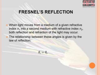


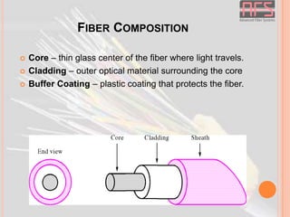


The document provides an overview of fiber optic technology including: - The basics of how optical fibers transmit light via total internal reflection - The different types of optical fibers like single-mode, multi-mode, and their variations - Components used in fiber optic systems like connectors, adapters, splitters, and attenuators - Causes of loss in optical fibers including absorption, scattering, modal dispersion, and more - Applications of fiber optics in telecommunications, networks, and more


