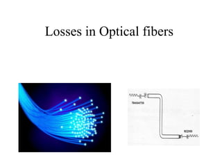
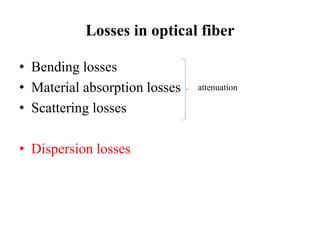
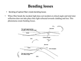
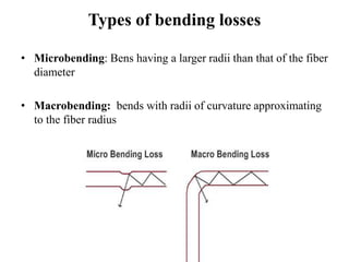
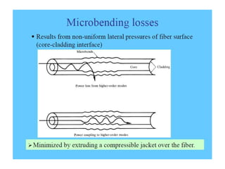
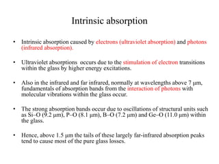
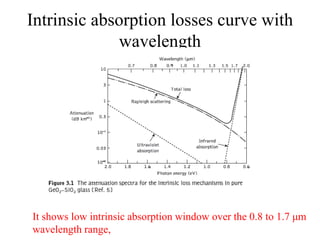
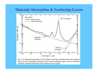
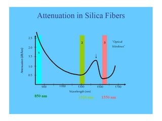
Losses in Optical fibers
Losses in optical fiber
• Bending losses
• Material absorption losses
• Scattering losses
• Dispersion losses
attenuation
Attenuation constant
• Attenuation is the loss of signal strength in cables or
connections.
• In optical fiber communications the attenuation is usually expressed in
decibels per unit length (i.e. dB km−1) following:
Pi= input power
Po= Output power
• The fiber with 5 dB per Km is considered as good fiber
Bending losses
• When fiber bends the incident light does not incident at critical angle and total inter
reflection does not take place thus light refracted towards cladding and lost. This
phenomena create bending losses.
• Bending of optical fiber create bending losses
Types of bending losses
• Microbending: Bens having a larger radii than that of the fiber
diameter
• Macrobending: bends with radii of curvature approximating
to the fiber radius
Macrobending losses
• Macro bends are bends on a fiber having a large radius of curvature (bend)/
diameter relative to the fiber core diameter that is r>>a where a, denotes the
core radius, and r the radius of curvature .
• Macro bend losses are usually encountered during the in-house and
installation process of the optic fiber.
• Macrobends can be characterized by a bend angle, bend diameter or a bend
radius also known as radius of curvature.
• When a fiber is bent the incident angle is compromised and total internal
reflection fails and thus the light is no longer confined and guided by the
core of the fiber.
•
Macrobending loss vs radius of bend
• For slight bends, the loss is extremely small and is not observed.
• As the radius of curvature decreases, the loss increases exponentially until
at a certain critical radius of curvature loss becomes observable.
• If the bend radius is made a bit smaller once this threshold point has been
reached, the losses suddenly become extremely large
Important expressions for macrobending
losses
Multi mode fiber
Single mode fiber
attenuation coefficient
• Critical radius of curvature Rc for single and multi mode fiber
• At critical radius and Below the bending losses are more
Reducing macrobending bending
losses
• Potential macrobending losses may be reduced by making
critical radius at lower value:
(a) designing fibers with large relative refractive index
differences;
(b) operating at the shortest wavelength possible.
• If critical radius is lesser we can bend optical fiber up to more at less bending
radius.
Microbending losses
• Microbending (bends too small to be seen with the naked eye) occur when
pressure is applied to the surface of an optical fiber.
• The pressure applied to the surface results in deformation of the fiber core
at the core-cladding interface.
• Microbending losses occur when surface pressure causes numerous tiny
contact point indentations on the fiber surface even though the fiber itself
may be laid out straight.
Microbending losses
• Microscopic meandering of the fiber core axis, known as
microbending, can be generated at any stage during the
manufacturing process, the cable installation process or during
service.
• This is due to environmental effects, particularly temperature
variations causing differential expansion or contraction .
• Microbending introduces slight surface imperfections which can
cause mode coupling between adjacent modes, which in turn creates
a radiative loss which is dependent on the amount of applied fiber
deformation, the length of fiber, and the exact distribution of power
among the different modes
Microbending losses
• microbending losses are mode dependent.
Removing microbending losses
• For less microbending losses it is important that the fiber is free
from irregular external pressure within the cable.
• Carefully controlled coating and cabling of the fiber is therefore
essential in order to minimize the cabled fiber attenuation.
• Furthermore, the fiber cabling must be capable of maintaining this
situation under all the strain and environmental conditions envisaged
in itslifetime.
Material absorption losses
• Absorption losses are separated into two
categories
• Intrinsic absorption losses ( occurs Due to
basic material glass SiO2 or GeO2)
• Extrinsic absorption losses (Occurs due to
impurities in fiber material)
Material absorption losses
Intrinsic absorption
• Intrinsic absorption caused by electrons (ultraviolet absorption) and photons
(infrared absorption).
• Ultraviolet absorptions occurs due to the stimulation of electron transitions
within the glass by higher energy excitations.
• Also in the infrared and far infrared, normally at wavelengths above 7 μm,
fundamentals of absorption bands from the interaction of photons with
molecular vibrations within the glass occur.
• The strong absorption bands occur due to oscillations of structural units such
as Si–O (9.2 μm), P–O (8.1 μm), B–O (7.2 μm) and Ge–O (11.0 μm) within
the glass.
• Hence, above 1.5 μm the tails of these largely far-infrared absorption peaks
tend to cause most of the pure glass losses.
Intrinsic absorption losses curve with
wavelength
It shows low intrinsic absorption window over the 0.8 to 1.7 μm
wavelength range,
Minimizing Intrinsic absorption losses
• However, the effects of both these processes may be
minimized by suitable choice of both core and cladding
compositions.
• For instance, in some nonoxide glasses such as fluorides and
chlorides, the infrared absorption peaks occur at much longer
wavelengths which are well into the far infrared (up to 50 μm),
giving less attenuation to longer wavelength transmission
compared with oxide glasses.
• So use of fluorides and chlorides instead of SiO2 create less
intrinsic absorption losses at comparatively longer wavelength.
Extrinsic absorption losses
Major impurities and extrinsic
absorption losses by them in fiber
OH impurities losses with wavelength
Extrinsic losses can be minimized by reducing metal
impurities and water molecules in fabrication process.
Losses ofc
Losses ofc
Losses ofc
Losses ofc
Losses ofc
Losses ofc
Losses ofc
Losses ofc
Losses ofc

Losses ofc

  • 1.
  • 3.
    Losses in opticalfiber • Bending losses • Material absorption losses • Scattering losses • Dispersion losses attenuation
  • 4.
    Attenuation constant • Attenuationis the loss of signal strength in cables or connections. • In optical fiber communications the attenuation is usually expressed in decibels per unit length (i.e. dB km−1) following: Pi= input power Po= Output power • The fiber with 5 dB per Km is considered as good fiber
  • 6.
    Bending losses • Whenfiber bends the incident light does not incident at critical angle and total inter reflection does not take place thus light refracted towards cladding and lost. This phenomena create bending losses. • Bending of optical fiber create bending losses
  • 7.
    Types of bendinglosses • Microbending: Bens having a larger radii than that of the fiber diameter • Macrobending: bends with radii of curvature approximating to the fiber radius
  • 8.
    Macrobending losses • Macrobends are bends on a fiber having a large radius of curvature (bend)/ diameter relative to the fiber core diameter that is r>>a where a, denotes the core radius, and r the radius of curvature . • Macro bend losses are usually encountered during the in-house and installation process of the optic fiber. • Macrobends can be characterized by a bend angle, bend diameter or a bend radius also known as radius of curvature. • When a fiber is bent the incident angle is compromised and total internal reflection fails and thus the light is no longer confined and guided by the core of the fiber. •
  • 9.
    Macrobending loss vsradius of bend • For slight bends, the loss is extremely small and is not observed. • As the radius of curvature decreases, the loss increases exponentially until at a certain critical radius of curvature loss becomes observable. • If the bend radius is made a bit smaller once this threshold point has been reached, the losses suddenly become extremely large
  • 11.
    Important expressions formacrobending losses Multi mode fiber Single mode fiber attenuation coefficient • Critical radius of curvature Rc for single and multi mode fiber • At critical radius and Below the bending losses are more
  • 12.
    Reducing macrobending bending losses •Potential macrobending losses may be reduced by making critical radius at lower value: (a) designing fibers with large relative refractive index differences; (b) operating at the shortest wavelength possible. • If critical radius is lesser we can bend optical fiber up to more at less bending radius.
  • 14.
    Microbending losses • Microbending(bends too small to be seen with the naked eye) occur when pressure is applied to the surface of an optical fiber. • The pressure applied to the surface results in deformation of the fiber core at the core-cladding interface. • Microbending losses occur when surface pressure causes numerous tiny contact point indentations on the fiber surface even though the fiber itself may be laid out straight.
  • 15.
    Microbending losses • Microscopicmeandering of the fiber core axis, known as microbending, can be generated at any stage during the manufacturing process, the cable installation process or during service. • This is due to environmental effects, particularly temperature variations causing differential expansion or contraction . • Microbending introduces slight surface imperfections which can cause mode coupling between adjacent modes, which in turn creates a radiative loss which is dependent on the amount of applied fiber deformation, the length of fiber, and the exact distribution of power among the different modes
  • 16.
    Microbending losses • microbendinglosses are mode dependent.
  • 17.
    Removing microbending losses •For less microbending losses it is important that the fiber is free from irregular external pressure within the cable. • Carefully controlled coating and cabling of the fiber is therefore essential in order to minimize the cabled fiber attenuation. • Furthermore, the fiber cabling must be capable of maintaining this situation under all the strain and environmental conditions envisaged in itslifetime.
  • 18.
    Material absorption losses •Absorption losses are separated into two categories • Intrinsic absorption losses ( occurs Due to basic material glass SiO2 or GeO2) • Extrinsic absorption losses (Occurs due to impurities in fiber material)
  • 19.
  • 20.
    Intrinsic absorption • Intrinsicabsorption caused by electrons (ultraviolet absorption) and photons (infrared absorption). • Ultraviolet absorptions occurs due to the stimulation of electron transitions within the glass by higher energy excitations. • Also in the infrared and far infrared, normally at wavelengths above 7 μm, fundamentals of absorption bands from the interaction of photons with molecular vibrations within the glass occur. • The strong absorption bands occur due to oscillations of structural units such as Si–O (9.2 μm), P–O (8.1 μm), B–O (7.2 μm) and Ge–O (11.0 μm) within the glass. • Hence, above 1.5 μm the tails of these largely far-infrared absorption peaks tend to cause most of the pure glass losses.
  • 21.
    Intrinsic absorption lossescurve with wavelength It shows low intrinsic absorption window over the 0.8 to 1.7 μm wavelength range,
  • 22.
    Minimizing Intrinsic absorptionlosses • However, the effects of both these processes may be minimized by suitable choice of both core and cladding compositions. • For instance, in some nonoxide glasses such as fluorides and chlorides, the infrared absorption peaks occur at much longer wavelengths which are well into the far infrared (up to 50 μm), giving less attenuation to longer wavelength transmission compared with oxide glasses. • So use of fluorides and chlorides instead of SiO2 create less intrinsic absorption losses at comparatively longer wavelength.
  • 23.
  • 24.
    Major impurities andextrinsic absorption losses by them in fiber
  • 25.
    OH impurities losseswith wavelength Extrinsic losses can be minimized by reducing metal impurities and water molecules in fabrication process.