Downloaded 26 times


![OFC SYSTEMS
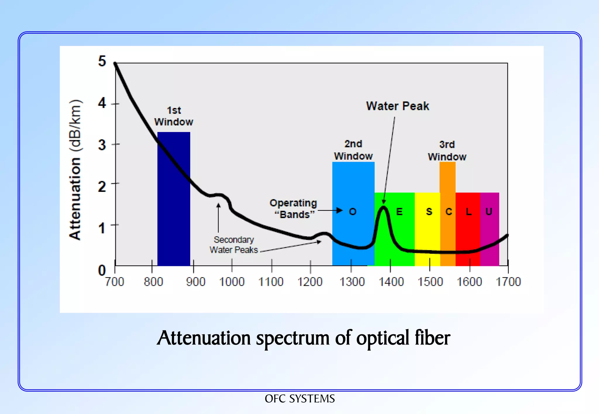
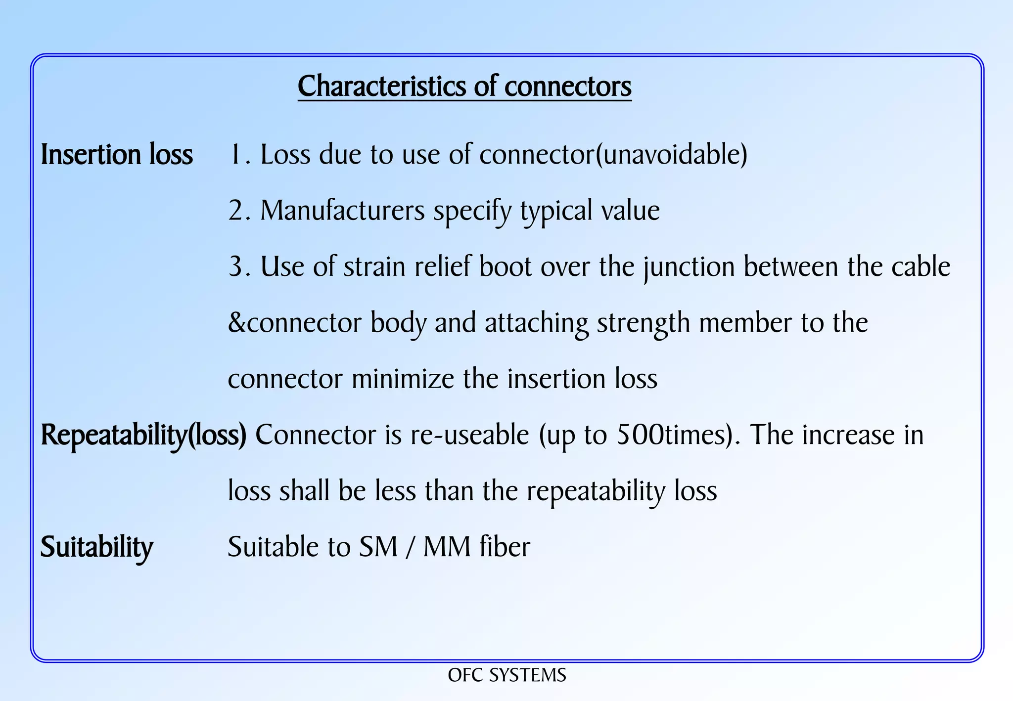
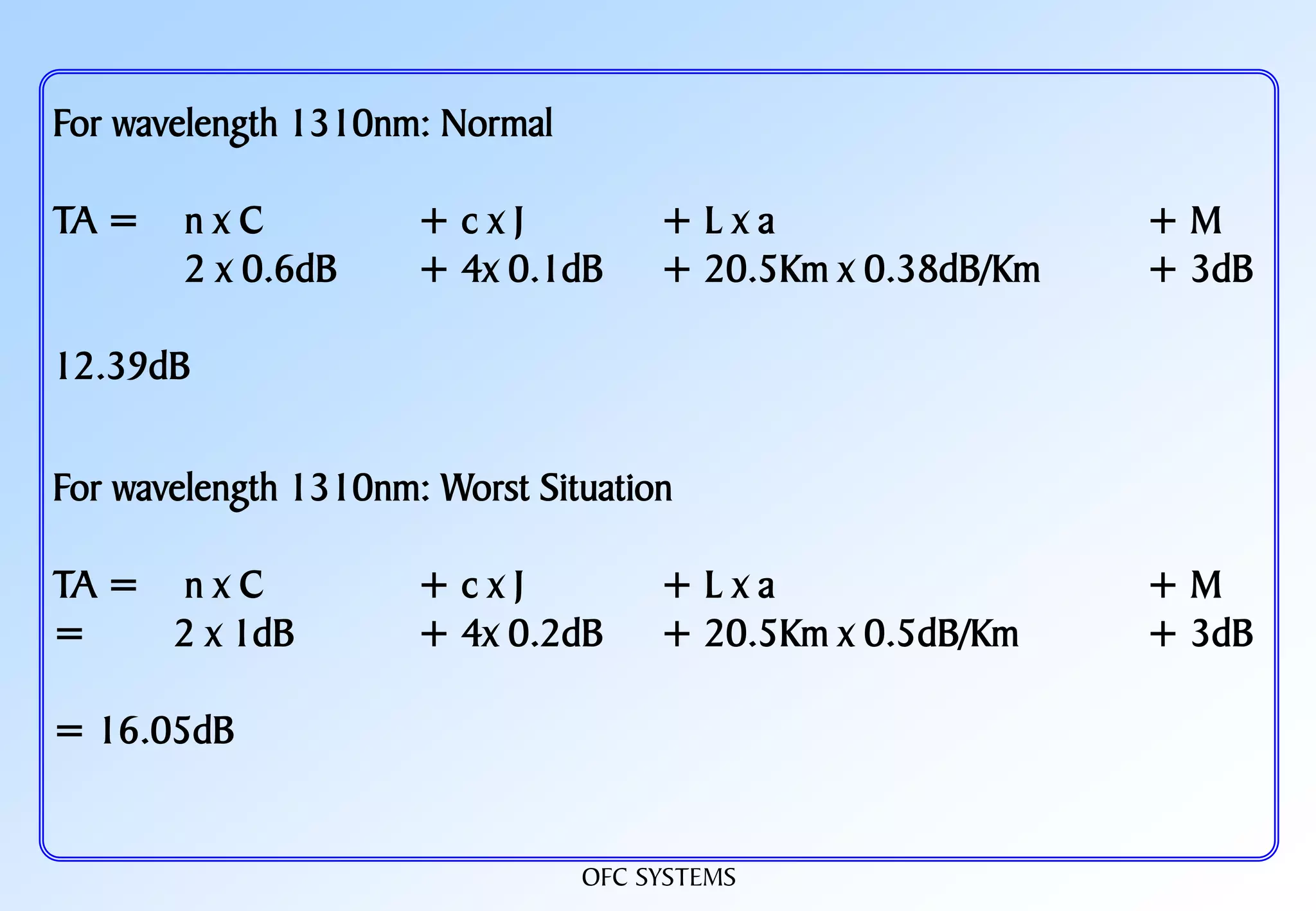
OFC LINK LOSS
LINK LOSS = [ Fiber length (Km) X Fiber attenuation per km] + [Splice loss x
No. of splices ] + [ Connector loss x No. of connectors ] + Safety margin
Assume a 40 Km long single mode link with 1310 nm with 2 connector pairs
and 5 splices
LINK LOSS = [ 40 X 0.4] + [0.1x 5] + [ 0.75 x 2] + 3 = 21 dB](https://image.slidesharecdn.com/ofcrtje-190826163819/75/OFC-65-2048.jpg)
![OFC SYSTEMS
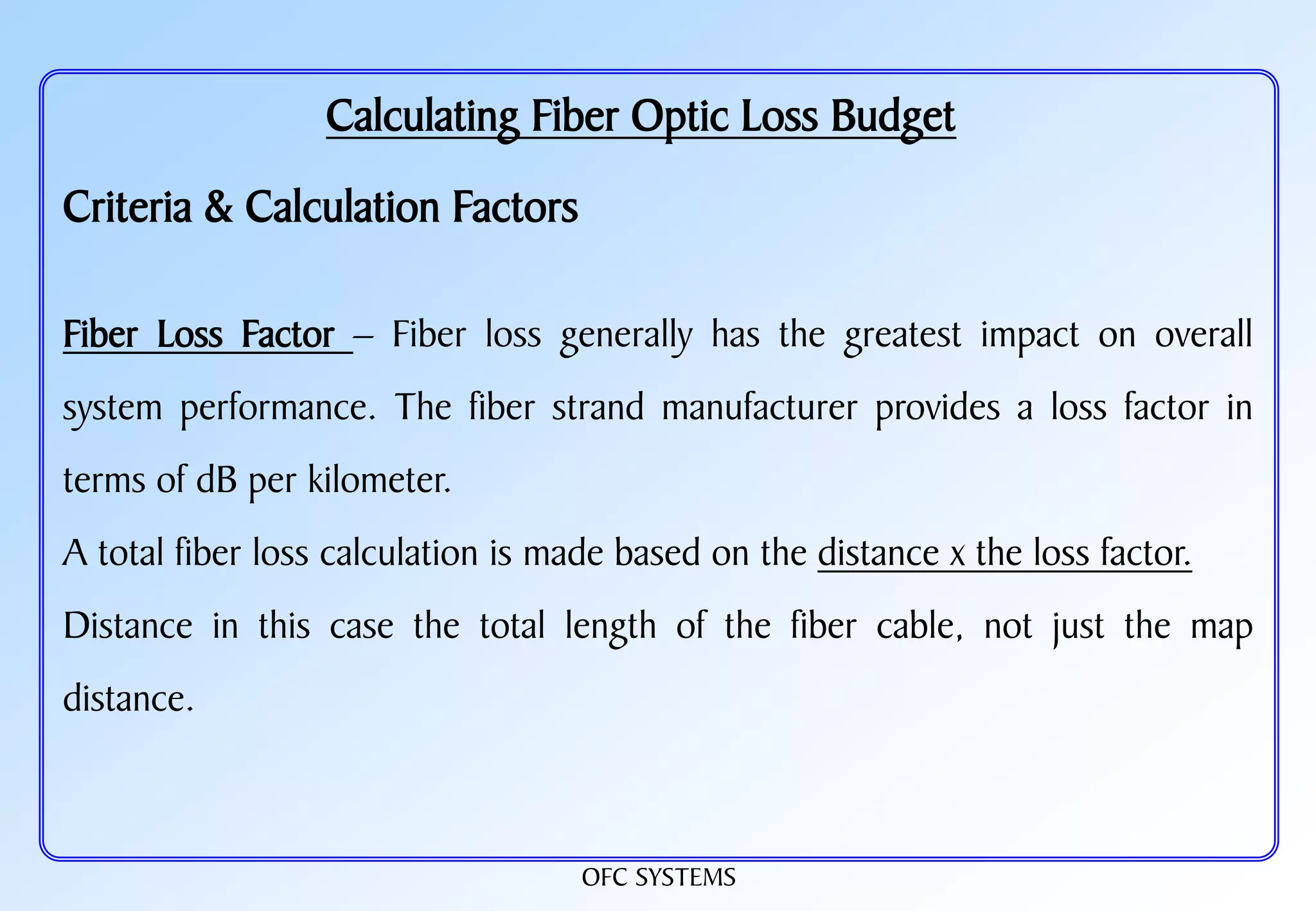
Estimate Fiber length
[ Optical budget ] - [Link loss ]
Fiber length=
[ Fiber loss / Km ]
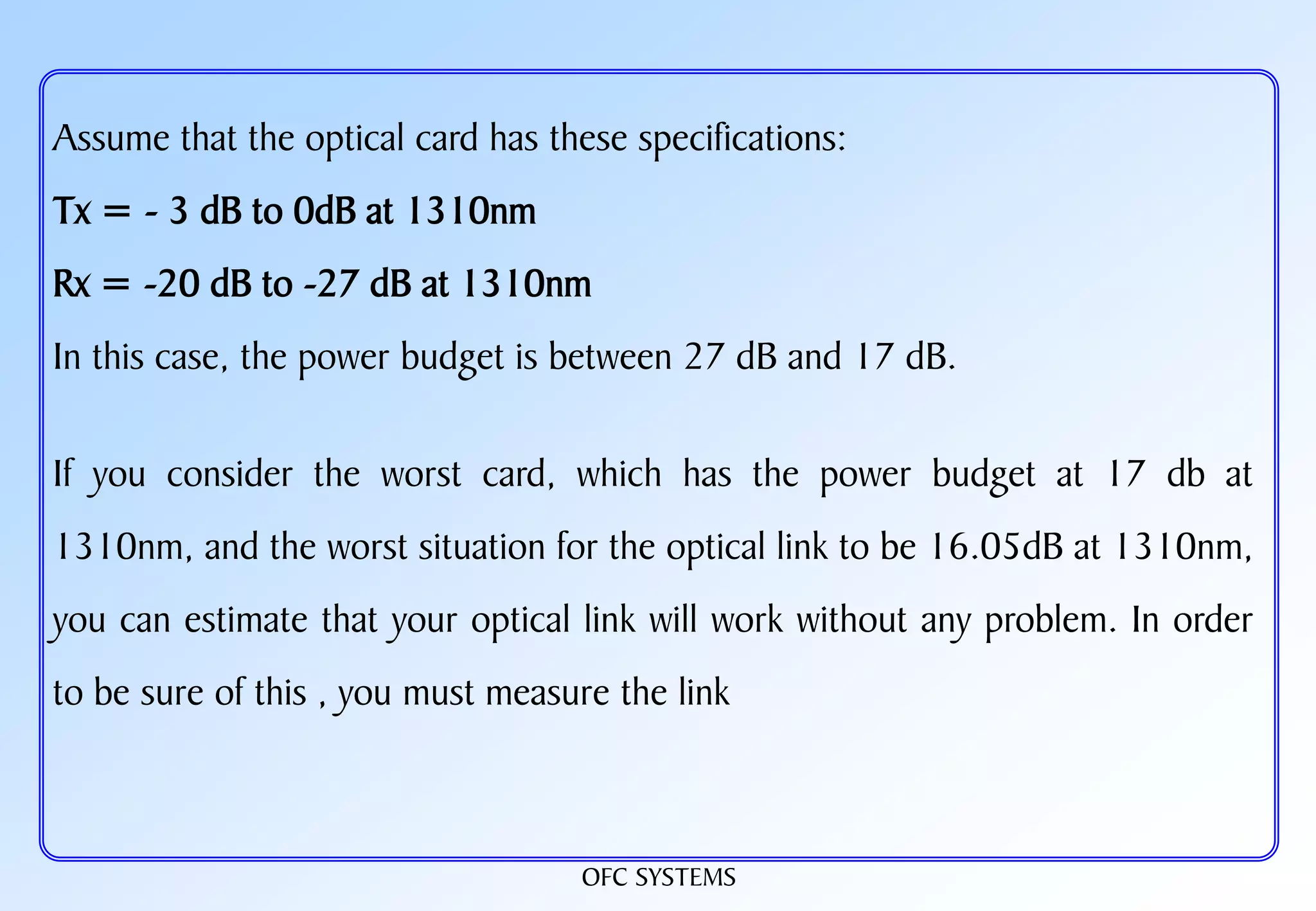
Fiber length = {[ Tx power – Rx sensitivity ]- [Splice loss x No. of
splices ]+ [ Connector loss x No. of connectors
] +( Safety margin)}÷ [ Fiber loss / Km ]](https://image.slidesharecdn.com/ofcrtje-190826163819/75/OFC-66-2048.jpg)


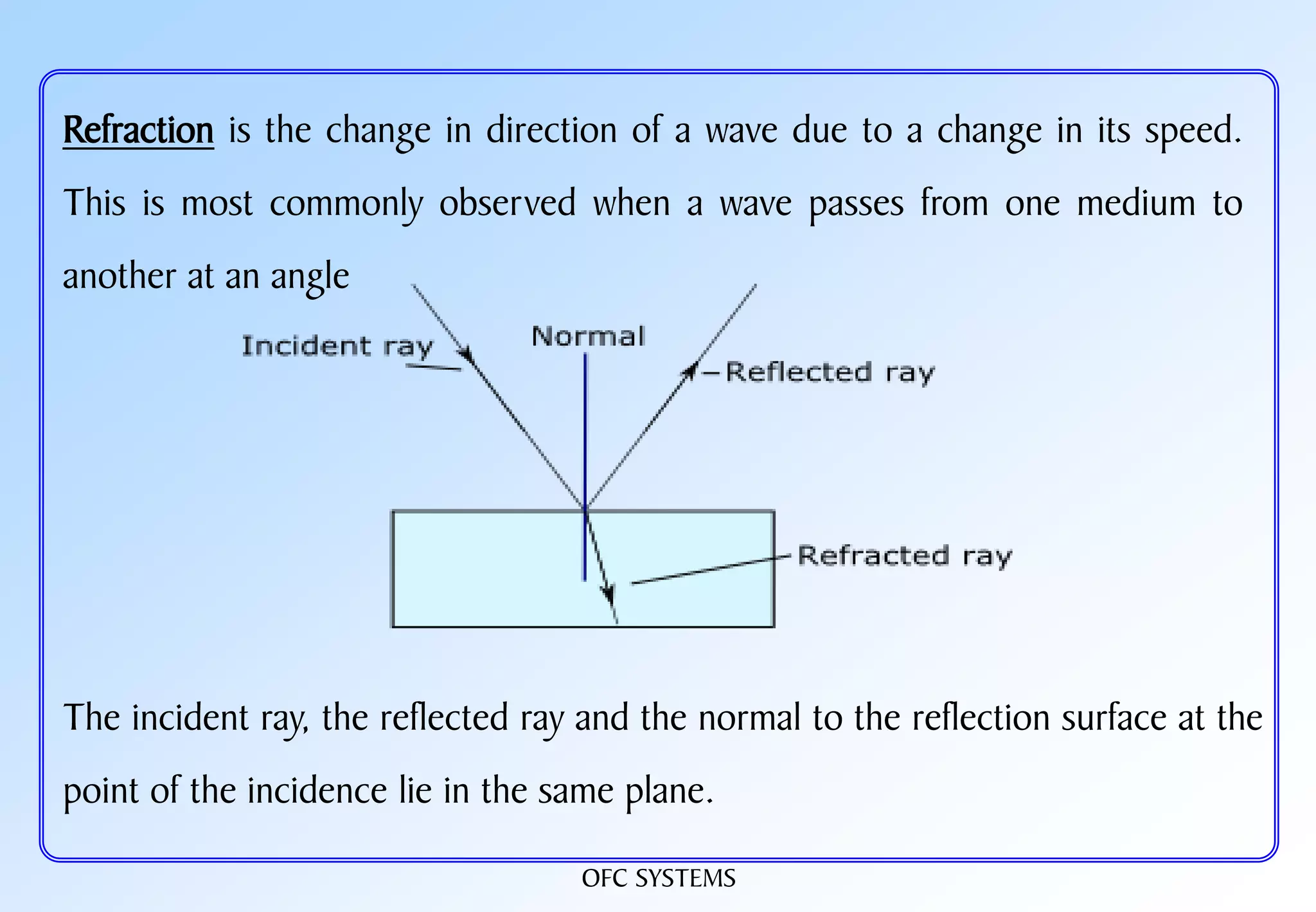
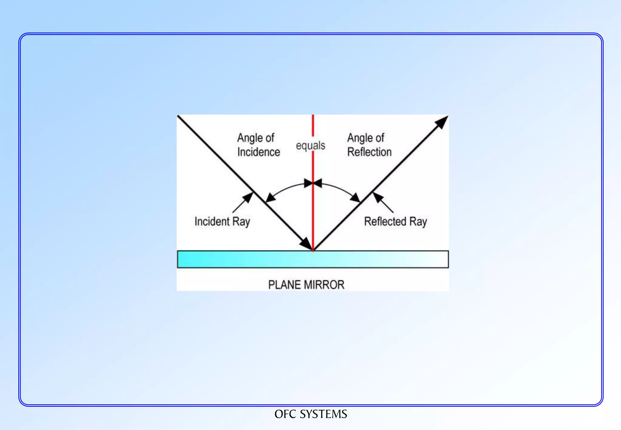
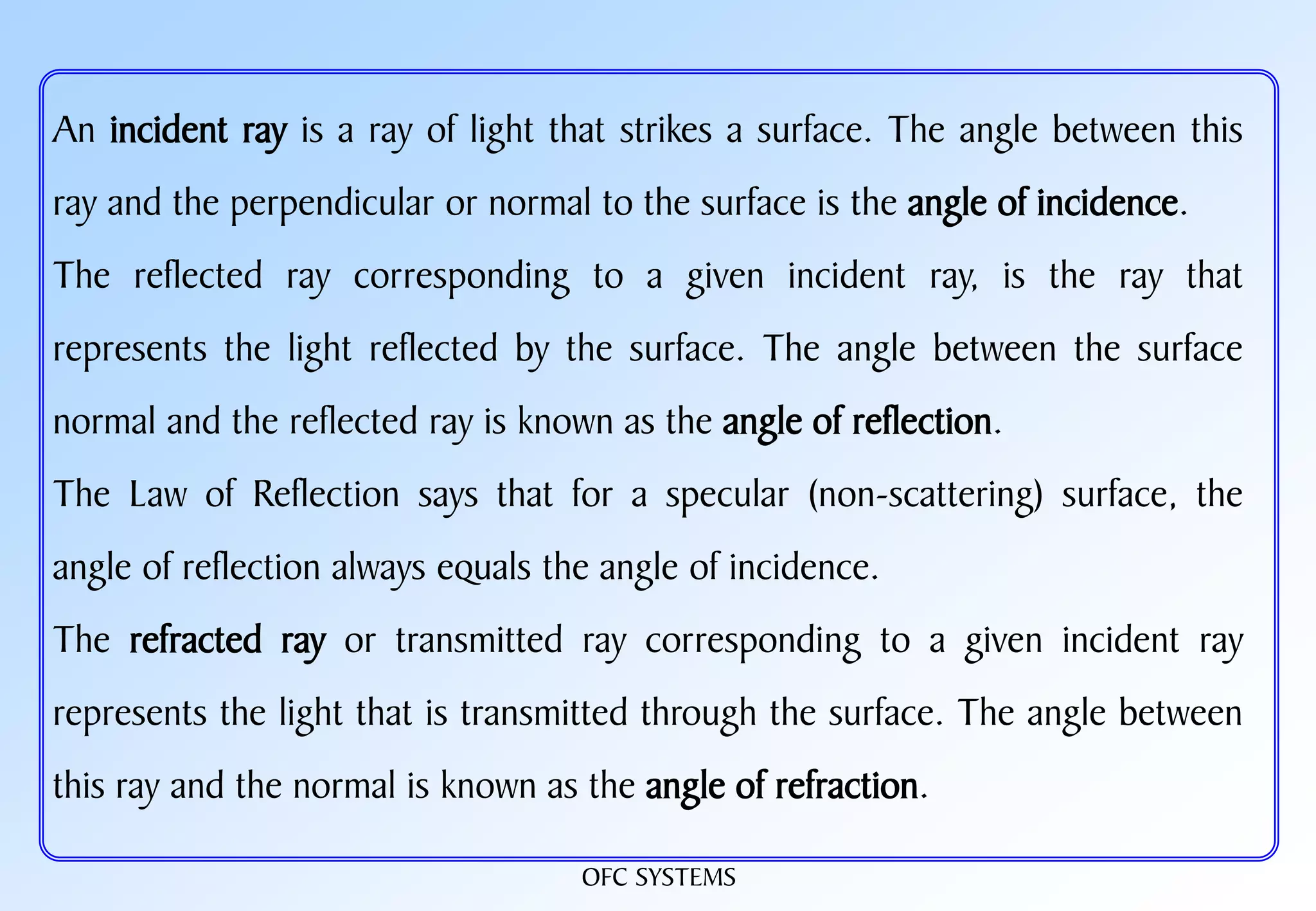
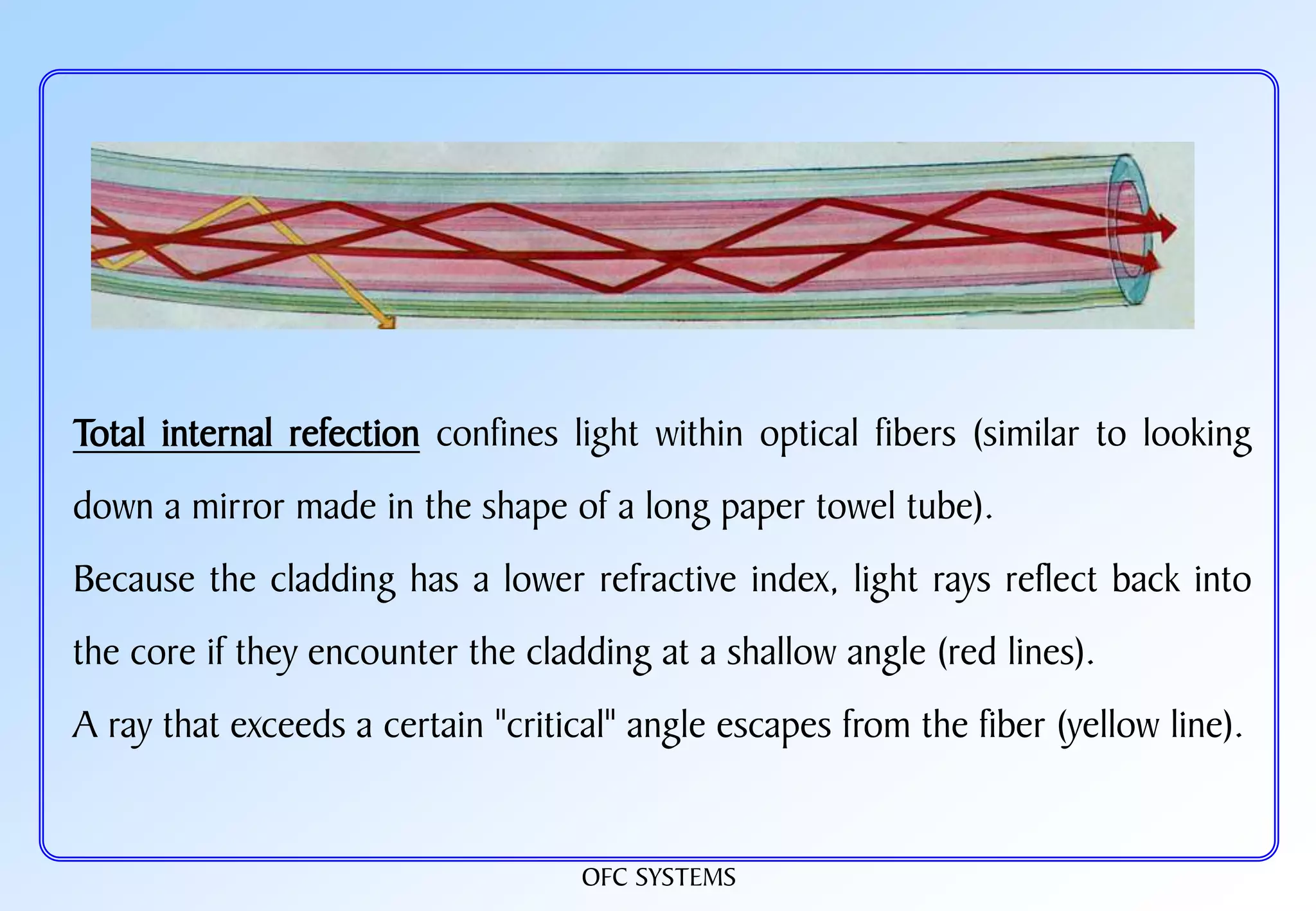
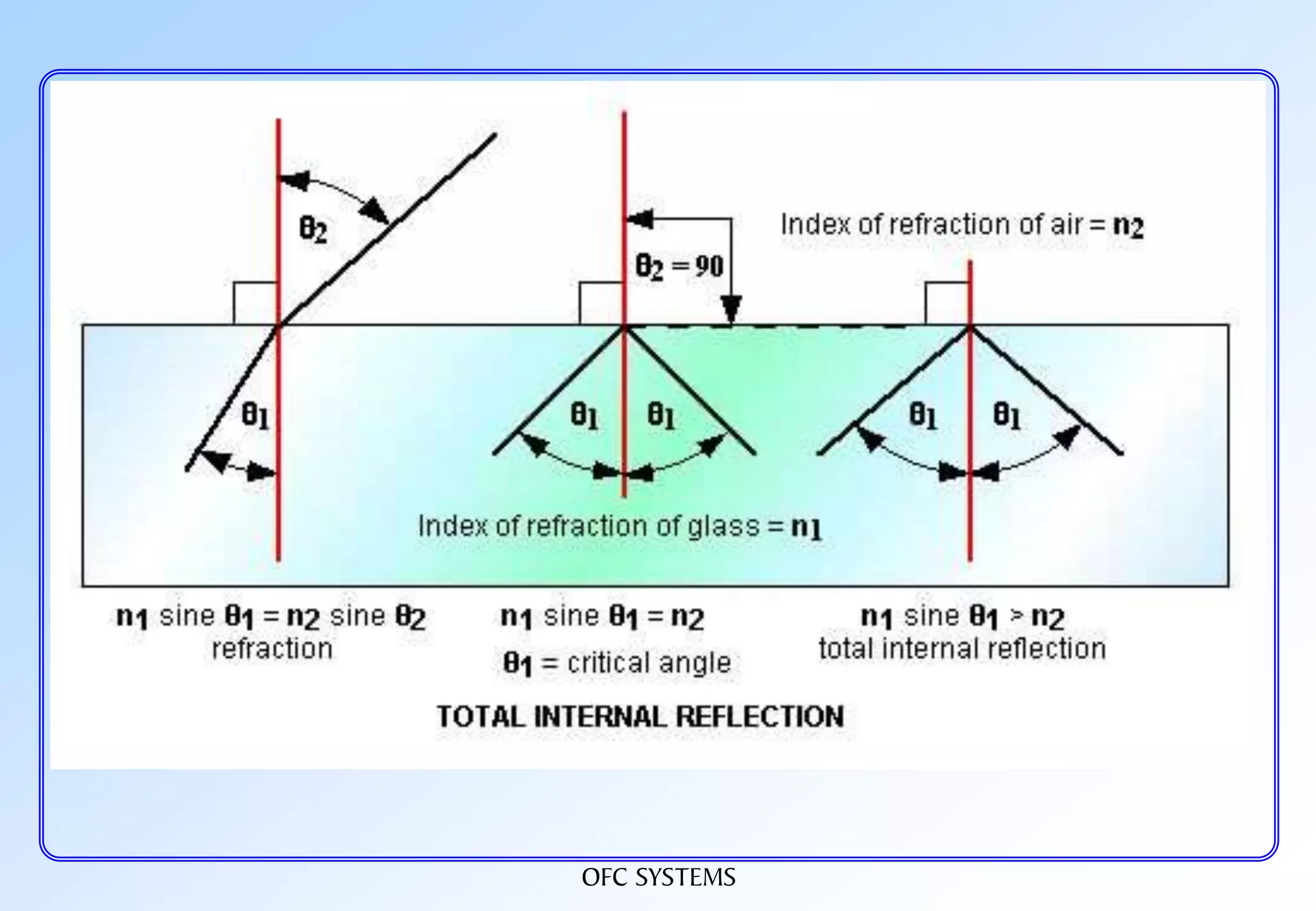
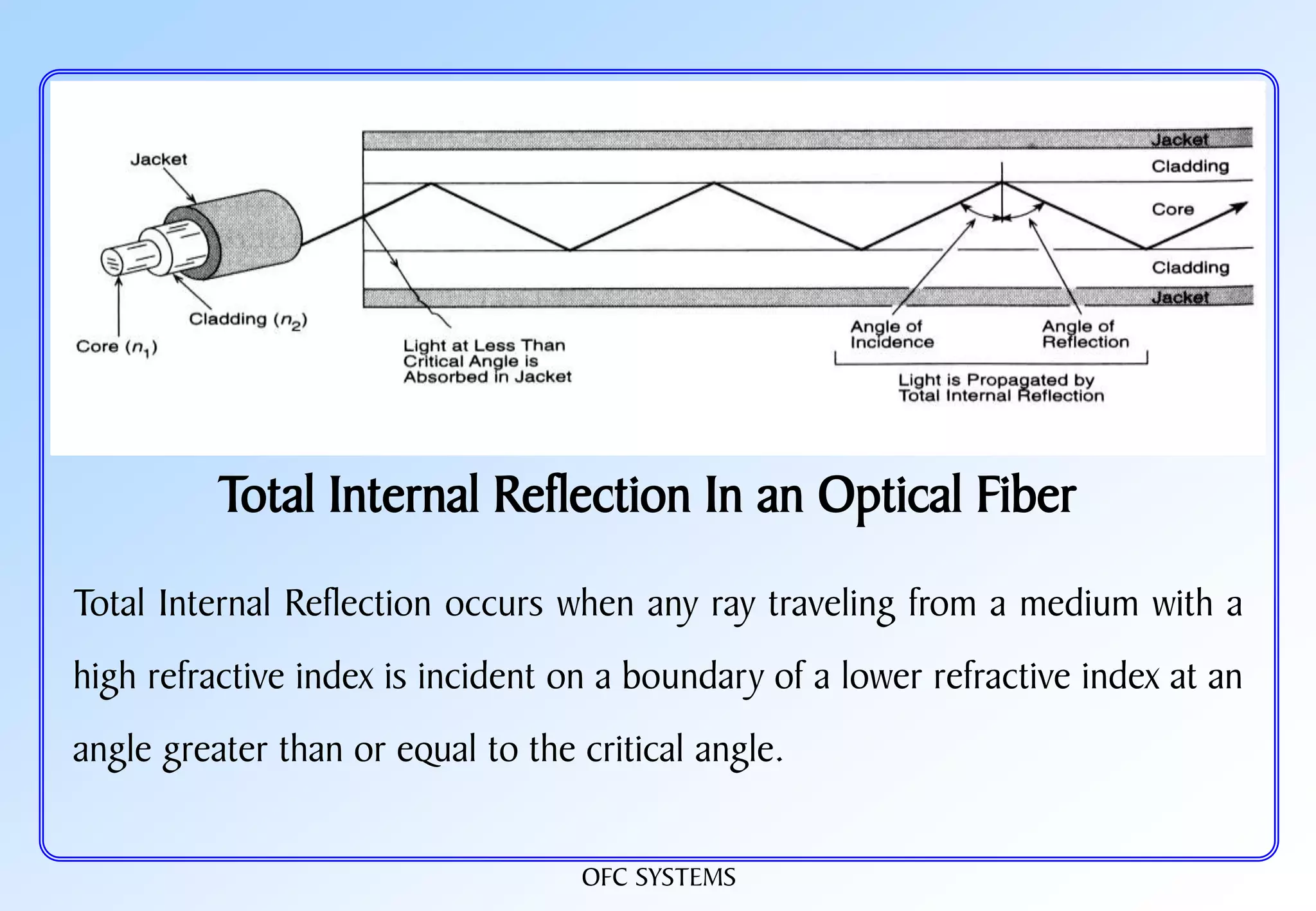
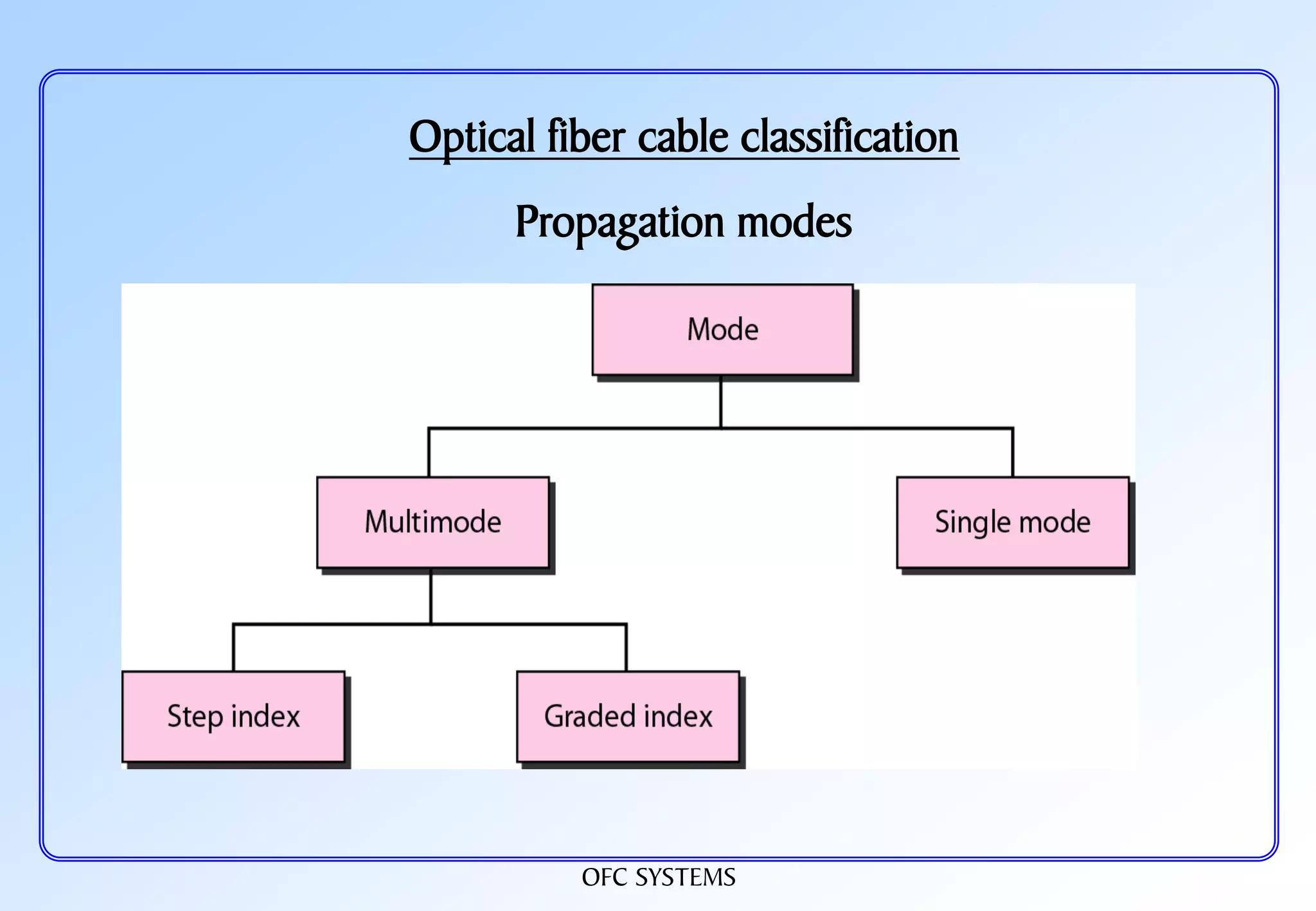
The document provides information about optical fiber communication (OFC) systems, including: 1. It discusses the basic components and principles of OFC systems such as the advantages of fiber optics, different types of fibers, propagation modes, dispersion, attenuation, and cable design. 2. It also defines fundamental optical concepts like refraction, reflection, critical angle, and total internal reflection which are important for light propagation in optical fibers. 3. Different fiber types are classified including single mode fiber, multimode fiber, and their standard specifications are discussed.


