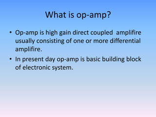
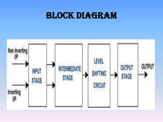
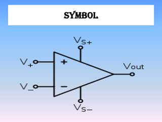
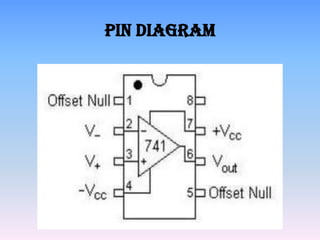
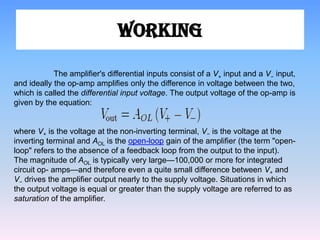
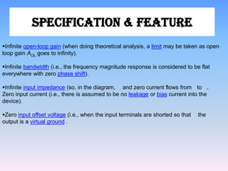
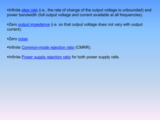
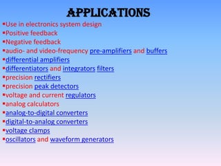
Patil Suraj Shrikant
  Msc-I (Electronic)
 Poona College,Pune
Operational –
  amplifier
What is op-amp?
• Op-amp is high gain direct coupled amplifire
  usually consisting of one or more differential
  amplifire.
• In present day op-amp is basic building block
  of electronic system.
Block diagram
Symbol
Pin diagram
WORKING

            The amplifier's differential inputs consist of a V+ input and a V− input,
and ideally the op-amp amplifies only the difference in voltage between the two,
which is called the differential input voltage. The output voltage of the op-amp is
given by the equation:


where V+ is the voltage at the non-inverting terminal, V− is the voltage at the
inverting terminal and AOL is the open-loop gain of the amplifier (the term "open-
loop" refers to the absence of a feedback loop from the output to the input).
The magnitude of AOL is typically very large—100,000 or more for integrated
circuit op- amps—and therefore even a quite small difference between V+ and
V− drives the amplifier output nearly to the supply voltage. Situations in which
the output voltage is equal or greater than the supply voltage are referred to as
saturation of the amplifier.
Specification & Feature
Infinite open-loop gain (when doing theoretical analysis, a limit may be taken as open
loop gain AOL goes to infinity).

Infinite bandwidth (i.e., the frequency magnitude response is considered to be flat
everywhere with zero phase shift).

Infinite input impedance (so, in the diagram, , and zero current flows from to .          )


Zero input current (i.e., there is assumed to be no leakage or bias current into the
device).

Zero input offset voltage (i.e., when the input terminals are shorted so that   ,   the
output is a virtual ground .
Infinite slew rate (i.e., the rate of change of the output voltage is unbounded) and
power bandwidth (full output voltage and current available at all frequencies).

Zero output impedance (i.e. so that output voltage does not vary with output
current).

Zero noise.

Infinite Common-mode rejection ratio (CMRR).

Infinite Power supply rejection ratio for both power supply rails.
Advantages
                 The use of negative feedback makes it easy to
adjust the voltage gain. The voltage gain obtained is
predictable
Dis-Advantages

 The disadvantages are the loss of voltage gain and the need
for a high impedance differential amplifier circuit. With the Op-
Amp these disadvantages are no longer valid, and most
amplifier systems are designed using op-amps with a negative
feedback loop to control the gain.
Applications
Use in electronics system design
Positive feedback
Negative feedback
audio- and video-frequency pre-amplifiers and buffers
differential amplifiers
differentiators and integrators filters
precision rectifiers
precision peak detectors
voltage and current regulators
analog calculators
analog-to-digital converters
digital-to-analog converters
voltage clamps
oscillators and waveform generators
Reference

Linear integrated circuit
WWW.Wikipedia.com
WWW.Google.com
THANKS
  …
premrajpatil2327@gmail.com

Op amp

  • 1.
    Patil Suraj Shrikant Msc-I (Electronic) Poona College,Pune
  • 2.
  • 3.
    What is op-amp? •Op-amp is high gain direct coupled amplifire usually consisting of one or more differential amplifire. • In present day op-amp is basic building block of electronic system.
  • 4.
  • 5.
  • 6.
  • 8.
    WORKING The amplifier's differential inputs consist of a V+ input and a V− input, and ideally the op-amp amplifies only the difference in voltage between the two, which is called the differential input voltage. The output voltage of the op-amp is given by the equation: where V+ is the voltage at the non-inverting terminal, V− is the voltage at the inverting terminal and AOL is the open-loop gain of the amplifier (the term "open- loop" refers to the absence of a feedback loop from the output to the input). The magnitude of AOL is typically very large—100,000 or more for integrated circuit op- amps—and therefore even a quite small difference between V+ and V− drives the amplifier output nearly to the supply voltage. Situations in which the output voltage is equal or greater than the supply voltage are referred to as saturation of the amplifier.
  • 9.
    Specification & Feature Infiniteopen-loop gain (when doing theoretical analysis, a limit may be taken as open loop gain AOL goes to infinity). Infinite bandwidth (i.e., the frequency magnitude response is considered to be flat everywhere with zero phase shift). Infinite input impedance (so, in the diagram, , and zero current flows from to . ) Zero input current (i.e., there is assumed to be no leakage or bias current into the device). Zero input offset voltage (i.e., when the input terminals are shorted so that , the output is a virtual ground .
  • 10.
    Infinite slew rate(i.e., the rate of change of the output voltage is unbounded) and power bandwidth (full output voltage and current available at all frequencies). Zero output impedance (i.e. so that output voltage does not vary with output current). Zero noise. Infinite Common-mode rejection ratio (CMRR). Infinite Power supply rejection ratio for both power supply rails.
  • 11.
    Advantages The use of negative feedback makes it easy to adjust the voltage gain. The voltage gain obtained is predictable
  • 12.
    Dis-Advantages The disadvantagesare the loss of voltage gain and the need for a high impedance differential amplifier circuit. With the Op- Amp these disadvantages are no longer valid, and most amplifier systems are designed using op-amps with a negative feedback loop to control the gain.
  • 13.
    Applications Use in electronicssystem design Positive feedback Negative feedback audio- and video-frequency pre-amplifiers and buffers differential amplifiers differentiators and integrators filters precision rectifiers precision peak detectors voltage and current regulators analog calculators analog-to-digital converters digital-to-analog converters voltage clamps oscillators and waveform generators
  • 14.
  • 15.