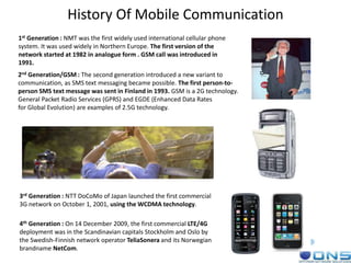
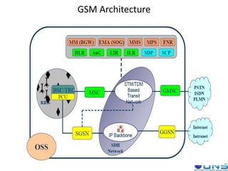
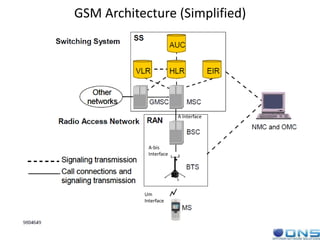
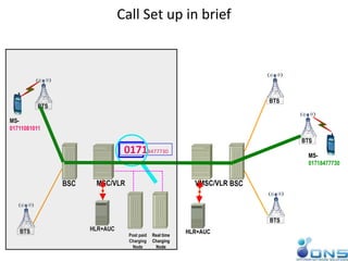
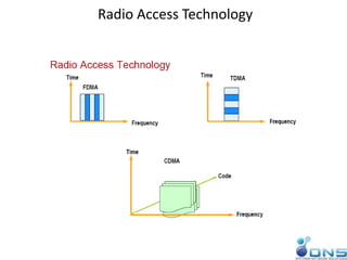
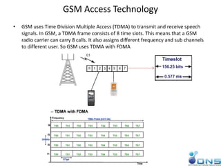
History Of Mobile Communication
1st Generation : NMT was the first widely used international cellular phone
system. It was used widely in Northern Europe. The first version of the
network started at 1982 in analogue form . GSM call was introduced in
1991.
2nd Generation/GSM : The second generation introduced a new variant to
communication, as SMS text messaging became possible. The first person-to-
person SMS text message was sent in Finland in 1993. GSM is a 2G technology.
General Packet Radio Services (GPRS) and EGDE (Enhanced Data Rates
for Global Evolution) are examples of 2.5G technology.
3rd Generation : NTT DoCoMo of Japan launched the first commercial
3G network on October 1, 2001, using the WCDMA technology.
4th Generation : On 14 December 2009, the first commercial LTE/4G
deployment was in the Scandinavian capitals Stockholm and Oslo by
the Swedish-Finnish network operator TeliaSonera and its Norwegian
brandname NetCom.
GSM Architecture
GSM Architecture (Simplified)
Um
Interface
A-bis
Interface
A Interface
Some Definitions
MSISDN: Mobile Station International Subscriber Directory
Number is a number used to identify a mobile phone number
internationally. Example: 8801711500036
IMSI: International Mobile Subscriber Identity.
Example: 470019876543210
IMSI Attach: When a Mobile Station or (MS) is switched on, IMSI
attach procedure is executed.
IMSI Detach: This procedure informs the network that the Mobile
Station is switched off or is unreachable.
TMSI : Temporary Mobile Subscriber Identity
IMEI: International Mobile Equipment Identity.
SIM: Subscriber Identity Module
MS: Mobile Station
Mobile Number Format
880 17 11500036
MCC MNC SN
Mobile Country Code Mobile Network Code Subscriber Number
MS= ME+ SIM
GSM Network Structure
• Cell
– A cell may be defined as an area of radio coverage for a BTS (Base Transceiver
Station) system. It is the smallest building block in a mobile network.
– Typically, cells are represented graphically by hexagons. There are two types
of cell:
• Omni directional cell
– An Omni-directional cell (or Omni cell) is served by a BTS with an antenna
which transmits equally in all directions (360 degrees).
• Sector cell
– A sector cell is the area of coverage from an antenna, which transmits, in a
given direction only.
– One BTS can serve as two-sectored sites and more commonly, three-sectored
sites.
Each cell is assigned a unique number called Cell Global Identity (CGI)
CGI= MCC+MNC+LAC+CI
• Location Area (LA)
- A Location Area (LA) is defined as a group of cells. Within the network a subscriber’s location is linked to
the LA in which they are currently located. The identity of the current LA is stored in the VLR. When an
MS crosses the boundary between two cells belonging to different LA’s, it must report its new Location
Area to the network. When there is a call for an MS, a paging message is broadcast within all the cells
belonging to the relevant LA.
The LAI is the international code for a location area.
LAI= MCC+MNC+LAC
GSM Network Structure
• PLMN Service Area
– A Public Land Mobile Network (PLMN) service area is the entire set of cells served by one network
operator and is defined as the area in which an operator offers radio coverage and access to its
network.
• GSM Service Area
– The GSM service area is the entire geographical area in which a subscriber can gain access to a GSM
network.
Mobile Station Key Terms
• MS can have one of the following states:
– Idle: the MS is ON but a call is not in progress
– Active: the MS is ON and a call is in progress
– Detached: the MS is OFF
GSM Traffic Cases
01718477730
BTS
BTS
BSC
BTS
01718477730
BTS
MS-
01711081011
BTS
BSC
HLR+AUC
VMSC/VLRMSC/VLR
HLR+AUC
MS-
01718477730
Post paid
Charging
Node
Real time
Charging
Node
Call Set up in brief
GSM Frequency Bands
Main Frequency bands are-
1) GSM 900
2) GSM 1800
GSM 800 and GSM 1900 are allocated to US operators as they allocated 900 and 1800 bands to other
purposes previously.
Radio Access Technology
GSM Access Technology
• GSM uses Time Division Multiple Access (TDMA) to transmit and receive speech
signals. In GSM, a TDMA frame consists of 8 time slots. This means that a GSM
radio carrier can carry 8 calls. It also assigns different frequency and sub channels
to different user. So GSM uses TDMA with FDMA
Frequency Division Duplex
• GSM channel bandwidth and carrier separation is 200 kHz. It also has both Uplink
and Downlink transmission.
• That is why GSM is a FDD+TDMA with FDMA technology.
Duplex Distance
ARFCN
ARFCN- Absolute Radio Frequency channel Number. Each frequency of a GSM
channel is designated by ARFCN.
One ARFCN denotes an Uplink frequency and it’s corresponding downlink
frequency.
Radio Channel
DOWNLINK
935 - 960 MHz
1805-1880 MHz
UPLINK
890-915 MHz
1710-1785 MHz Air Interface
Cell Site
Mobile
Physical & Logical Channel
• Physical Channel
– The physical channel is the medium over which the information is carried. One Timeslot of a GSM
channel which is of 0.577ms or 156.25 bit duration long.
• Logical Channel
– The logical channel consists of the information carried over the physical channels. Like TCH, SDCCH,
FACCH etc.
Two types of logical channels are there-
• Traffic channels- Transmits traffic information, include data and speech.
• Control Channels- Also known as Signaling Channel, transmits all kinds of control
information.
Logical Channels
Logical Channel Functions
Burst Types
TDMA Frame Structure
Traffic channel MF Control Channel MF
Frame Structure
Burst and Frame Structure
GSM Voice Transmission & Reception
Speech Coding
Convolutional
Coding
Interleaving Burst forming Modulation
Airinterface
DemodulationDeInterleaving
Speech
decodingDecoded
Speech
Convolutional
decoding
Channel coding
Speech
• Speech coding - to compress speech
• Channel coding – to detect and correct errors at the received speech
• Modulation - to fit bits into channel characteristics. GSM uses Gaussian Minimum
Shift Keying (GMSK) and is a form of phase modulation
• Transmission Rate- In GSM the net bit rate over the air interface is 270kbit/s
Signal Transmission Problems
• Path Loss
– The ratio of the transmitted power to the power which would be received by an receiver (isotropic
antenna) is the Path Loss. Normally expressed in dB
Path Loss formula (Okumura-Hata)
• Shadowing
– Shadowing occurs when there are physical obstacles including hills and buildings between the BTS
and the MS. The obstacles create a shadowing effect which can decrease the received signal
strength. A signal influenced by fading varies in signal strength. Drops in strength are called fading
dips.
Signal Transmission Problems
• Multipath Fading
– Multipath fading occurs when there is more than one transmission path to the MS or BTS, and
therefore more than one signal is arriving at the receiver. This may be due to buildings or mountains,
either close to or far from the receiving device.
Two types of Multipath Fading
• Rayleigh Fading
– This occurs when a signal takes more than one path between the MS and BTS antennas. The received
signal is the sum of many identical signals that differ only in phase
Signal Transmission Problems
• Time Dispersion
– Time dispersion causes Inter-Symbol Interference (ISI) where consecutive symbols (bits) interfere
with each other making it difficult for the receiver to determine which symbol is the correct one.
• Time Alignment
– Each MS on a call is allocated a time slot on a TDMA frame. This is an amount of time during which
the MS transmits information to the BTS. The information must also arrive at the BTS within that
time slot. The time alignment problem occurs when part of the information transmitted by an MS
does not arrive within the allocated time slot. Instead, that part may arrive during the next time slot,
and may interfere with information from another MS using that other time slot. A large distance
between the MS and the BTS causes time alignment.
Signal loss & Interference
• Combined Signal Loss
Radio Techniques
• Power Control- Both Uplink and Downlink power settings can be controlled independently and
individually. Saves battery power. Reduces co-channel and adjacent channel interference
• DTX, DRX & VAD- Discontinuous transmission, discontinuous reception and voice activity detection.
• Timing advance- Timing advance is a solution specifically designed to counteract the problem of time
alignment. It works by instructing the mis-aligned MS to transmit its burst earlier or later than it normally
would. In GSM, the timing advance information relates to bit times.
• Frequency Re-Use- Frequency bandwidth is limited. So frequency re-use scheme is used along with a
low power sectorial antenna in the BTS to accommodate huge users in a small geographical area.
Frequency re-use should be tight but should not be re-used among neighbor cells.
• Adaptive Equalization- Eight sets of predefined known bit patterns exist, known as training sequences.
These are known to the BTS and the MS. The MS and BTS include the training sequence in its
transmissions. The other party receives the transmission and examines the training sequence within it.
The received training sequence is compared with the known training sequence that is used in this cell. It
can be assumed that problems in the radio path affected these bits must also have had a similar affect on
the speech data bits sent in the same burst. The receiver begins a process in which it uses its knowledge of
what happened the training sequence to correct the speech data bits of the transmission.
• Diversity- Receive diversity provides an effective technique for both overcoming the impact of fading
across the radio channel and increasing the received signal to interference ratio. The former is achieved by
ensuring “uncorrelated” fading between antenna branches i.e. not all antennas experience fades at the
same time.
• Diversity can be of-
– Time Diversity(Coding, Interleaving)
– Frequency Diversity (Frequency hopping)
– Space Diversity (Multiple antennas)
– Polarization Diversity (Dual polarized antennas)
– Multipath Diversity (Equalizer)
Frequency Hopping
• Rayleigh fading is frequency dependent. This means that the fading dips occur at different places for different
frequencies. To benefit from this fact, it is possible for the BTS and MS to hop from frequency to frequency
during a call. The frequency hopping of the BTS and MS is synchronized. In GSM there are 64 patterns of
frequency hopping, one of them is a simple cyclic or sequential pattern. The remaining 63 are known as
pseudo-random patterns, which an operator can choose from. Two types of hopping are supported by the BSC:
- Baseband hopping involves hopping between frequencies on different transceivers in a cell.
- Synthesizer hopping involves hopping from frequency to frequency on the same transceiver in a cell.
Baseband hopping
Synthesizer hopping
Transmitter characteristics
Sensitivity- The lowest power that can be received and yet the message can still be interpreted.
MS Sensitivity is -104 dBm
BTS Sensitivity is -110 dBm
Antenna Power Basic Units
Antenna
Antenna Radiation Pattern
Antenna Tilting
Antenna tilting
Feeder & Connectors
Combiners
Types of Combiners

Ons training day 1

  • 2.
    History Of MobileCommunication 1st Generation : NMT was the first widely used international cellular phone system. It was used widely in Northern Europe. The first version of the network started at 1982 in analogue form . GSM call was introduced in 1991. 2nd Generation/GSM : The second generation introduced a new variant to communication, as SMS text messaging became possible. The first person-to- person SMS text message was sent in Finland in 1993. GSM is a 2G technology. General Packet Radio Services (GPRS) and EGDE (Enhanced Data Rates for Global Evolution) are examples of 2.5G technology. 3rd Generation : NTT DoCoMo of Japan launched the first commercial 3G network on October 1, 2001, using the WCDMA technology. 4th Generation : On 14 December 2009, the first commercial LTE/4G deployment was in the Scandinavian capitals Stockholm and Oslo by the Swedish-Finnish network operator TeliaSonera and its Norwegian brandname NetCom.
  • 3.
  • 4.
  • 5.
    Some Definitions MSISDN: MobileStation International Subscriber Directory Number is a number used to identify a mobile phone number internationally. Example: 8801711500036 IMSI: International Mobile Subscriber Identity. Example: 470019876543210 IMSI Attach: When a Mobile Station or (MS) is switched on, IMSI attach procedure is executed. IMSI Detach: This procedure informs the network that the Mobile Station is switched off or is unreachable. TMSI : Temporary Mobile Subscriber Identity IMEI: International Mobile Equipment Identity. SIM: Subscriber Identity Module MS: Mobile Station Mobile Number Format 880 17 11500036 MCC MNC SN Mobile Country Code Mobile Network Code Subscriber Number MS= ME+ SIM
  • 6.
    GSM Network Structure •Cell – A cell may be defined as an area of radio coverage for a BTS (Base Transceiver Station) system. It is the smallest building block in a mobile network. – Typically, cells are represented graphically by hexagons. There are two types of cell: • Omni directional cell – An Omni-directional cell (or Omni cell) is served by a BTS with an antenna which transmits equally in all directions (360 degrees). • Sector cell – A sector cell is the area of coverage from an antenna, which transmits, in a given direction only. – One BTS can serve as two-sectored sites and more commonly, three-sectored sites. Each cell is assigned a unique number called Cell Global Identity (CGI) CGI= MCC+MNC+LAC+CI • Location Area (LA) - A Location Area (LA) is defined as a group of cells. Within the network a subscriber’s location is linked to the LA in which they are currently located. The identity of the current LA is stored in the VLR. When an MS crosses the boundary between two cells belonging to different LA’s, it must report its new Location Area to the network. When there is a call for an MS, a paging message is broadcast within all the cells belonging to the relevant LA. The LAI is the international code for a location area. LAI= MCC+MNC+LAC
  • 7.
    GSM Network Structure •PLMN Service Area – A Public Land Mobile Network (PLMN) service area is the entire set of cells served by one network operator and is defined as the area in which an operator offers radio coverage and access to its network. • GSM Service Area – The GSM service area is the entire geographical area in which a subscriber can gain access to a GSM network.
  • 8.
    Mobile Station KeyTerms • MS can have one of the following states: – Idle: the MS is ON but a call is not in progress – Active: the MS is ON and a call is in progress – Detached: the MS is OFF GSM Traffic Cases
  • 9.
  • 10.
    GSM Frequency Bands MainFrequency bands are- 1) GSM 900 2) GSM 1800 GSM 800 and GSM 1900 are allocated to US operators as they allocated 900 and 1800 bands to other purposes previously.
  • 11.
  • 12.
    GSM Access Technology •GSM uses Time Division Multiple Access (TDMA) to transmit and receive speech signals. In GSM, a TDMA frame consists of 8 time slots. This means that a GSM radio carrier can carry 8 calls. It also assigns different frequency and sub channels to different user. So GSM uses TDMA with FDMA
  • 13.
    Frequency Division Duplex •GSM channel bandwidth and carrier separation is 200 kHz. It also has both Uplink and Downlink transmission. • That is why GSM is a FDD+TDMA with FDMA technology. Duplex Distance
  • 14.
    ARFCN ARFCN- Absolute RadioFrequency channel Number. Each frequency of a GSM channel is designated by ARFCN. One ARFCN denotes an Uplink frequency and it’s corresponding downlink frequency. Radio Channel DOWNLINK 935 - 960 MHz 1805-1880 MHz UPLINK 890-915 MHz 1710-1785 MHz Air Interface Cell Site Mobile
  • 15.
    Physical & LogicalChannel • Physical Channel – The physical channel is the medium over which the information is carried. One Timeslot of a GSM channel which is of 0.577ms or 156.25 bit duration long. • Logical Channel – The logical channel consists of the information carried over the physical channels. Like TCH, SDCCH, FACCH etc. Two types of logical channels are there- • Traffic channels- Transmits traffic information, include data and speech. • Control Channels- Also known as Signaling Channel, transmits all kinds of control information.
  • 16.
  • 17.
  • 18.
  • 19.
    TDMA Frame Structure Trafficchannel MF Control Channel MF
  • 20.
  • 21.
    Burst and FrameStructure
  • 22.
    GSM Voice Transmission& Reception Speech Coding Convolutional Coding Interleaving Burst forming Modulation Airinterface DemodulationDeInterleaving Speech decodingDecoded Speech Convolutional decoding Channel coding Speech • Speech coding - to compress speech • Channel coding – to detect and correct errors at the received speech • Modulation - to fit bits into channel characteristics. GSM uses Gaussian Minimum Shift Keying (GMSK) and is a form of phase modulation • Transmission Rate- In GSM the net bit rate over the air interface is 270kbit/s
  • 23.
    Signal Transmission Problems •Path Loss – The ratio of the transmitted power to the power which would be received by an receiver (isotropic antenna) is the Path Loss. Normally expressed in dB Path Loss formula (Okumura-Hata) • Shadowing – Shadowing occurs when there are physical obstacles including hills and buildings between the BTS and the MS. The obstacles create a shadowing effect which can decrease the received signal strength. A signal influenced by fading varies in signal strength. Drops in strength are called fading dips.
  • 24.
    Signal Transmission Problems •Multipath Fading – Multipath fading occurs when there is more than one transmission path to the MS or BTS, and therefore more than one signal is arriving at the receiver. This may be due to buildings or mountains, either close to or far from the receiving device. Two types of Multipath Fading • Rayleigh Fading – This occurs when a signal takes more than one path between the MS and BTS antennas. The received signal is the sum of many identical signals that differ only in phase
  • 25.
    Signal Transmission Problems •Time Dispersion – Time dispersion causes Inter-Symbol Interference (ISI) where consecutive symbols (bits) interfere with each other making it difficult for the receiver to determine which symbol is the correct one. • Time Alignment – Each MS on a call is allocated a time slot on a TDMA frame. This is an amount of time during which the MS transmits information to the BTS. The information must also arrive at the BTS within that time slot. The time alignment problem occurs when part of the information transmitted by an MS does not arrive within the allocated time slot. Instead, that part may arrive during the next time slot, and may interfere with information from another MS using that other time slot. A large distance between the MS and the BTS causes time alignment.
  • 26.
    Signal loss &Interference • Combined Signal Loss
  • 27.
    Radio Techniques • PowerControl- Both Uplink and Downlink power settings can be controlled independently and individually. Saves battery power. Reduces co-channel and adjacent channel interference • DTX, DRX & VAD- Discontinuous transmission, discontinuous reception and voice activity detection. • Timing advance- Timing advance is a solution specifically designed to counteract the problem of time alignment. It works by instructing the mis-aligned MS to transmit its burst earlier or later than it normally would. In GSM, the timing advance information relates to bit times. • Frequency Re-Use- Frequency bandwidth is limited. So frequency re-use scheme is used along with a low power sectorial antenna in the BTS to accommodate huge users in a small geographical area. Frequency re-use should be tight but should not be re-used among neighbor cells. • Adaptive Equalization- Eight sets of predefined known bit patterns exist, known as training sequences. These are known to the BTS and the MS. The MS and BTS include the training sequence in its transmissions. The other party receives the transmission and examines the training sequence within it. The received training sequence is compared with the known training sequence that is used in this cell. It can be assumed that problems in the radio path affected these bits must also have had a similar affect on the speech data bits sent in the same burst. The receiver begins a process in which it uses its knowledge of what happened the training sequence to correct the speech data bits of the transmission. • Diversity- Receive diversity provides an effective technique for both overcoming the impact of fading across the radio channel and increasing the received signal to interference ratio. The former is achieved by ensuring “uncorrelated” fading between antenna branches i.e. not all antennas experience fades at the same time. • Diversity can be of- – Time Diversity(Coding, Interleaving) – Frequency Diversity (Frequency hopping) – Space Diversity (Multiple antennas) – Polarization Diversity (Dual polarized antennas) – Multipath Diversity (Equalizer)
  • 28.
    Frequency Hopping • Rayleighfading is frequency dependent. This means that the fading dips occur at different places for different frequencies. To benefit from this fact, it is possible for the BTS and MS to hop from frequency to frequency during a call. The frequency hopping of the BTS and MS is synchronized. In GSM there are 64 patterns of frequency hopping, one of them is a simple cyclic or sequential pattern. The remaining 63 are known as pseudo-random patterns, which an operator can choose from. Two types of hopping are supported by the BSC: - Baseband hopping involves hopping between frequencies on different transceivers in a cell. - Synthesizer hopping involves hopping from frequency to frequency on the same transceiver in a cell. Baseband hopping Synthesizer hopping
  • 29.
    Transmitter characteristics Sensitivity- Thelowest power that can be received and yet the message can still be interpreted. MS Sensitivity is -104 dBm BTS Sensitivity is -110 dBm
  • 30.
  • 31.
  • 32.
  • 33.
  • 34.
  • 35.
  • 36.
  • 37.
  • 38.