Download as PDF, PPTX

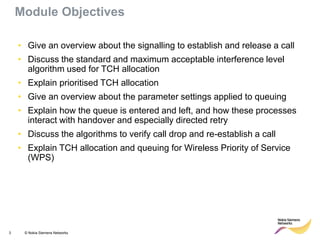
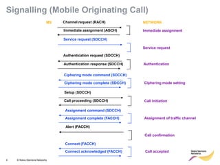
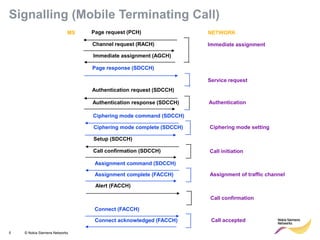
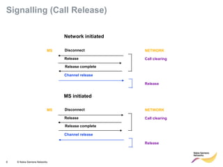
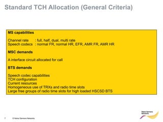
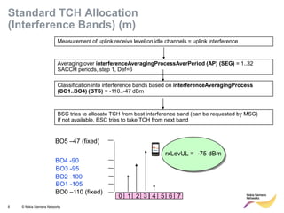
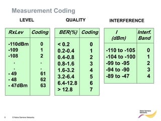
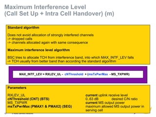
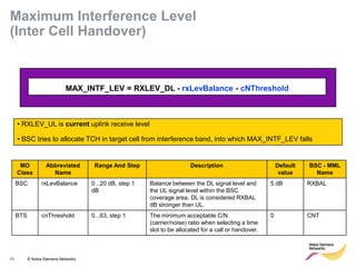
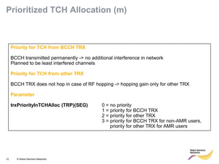
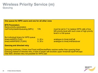

This document provides an overview of radio resource management for cellular networks. It discusses topics like call signaling, traffic channel allocation algorithms, interference level measurements, prioritized allocation, queuing parameters and processes for entering and leaving the queue. The document is copyrighted material from Nokia Siemens Networks and cannot be copied or shared without their permission.


![14 gsm bss network kpi (call setup time) optimization manual[1].doc](https://cdn.slidesharecdn.com/ss_thumbnails/14gsmbssnetworkkpicallsetuptimeoptimizationmanual1-140618022447-phpapp02-thumbnail.jpg?width=640&height=640&fit=bounds)


