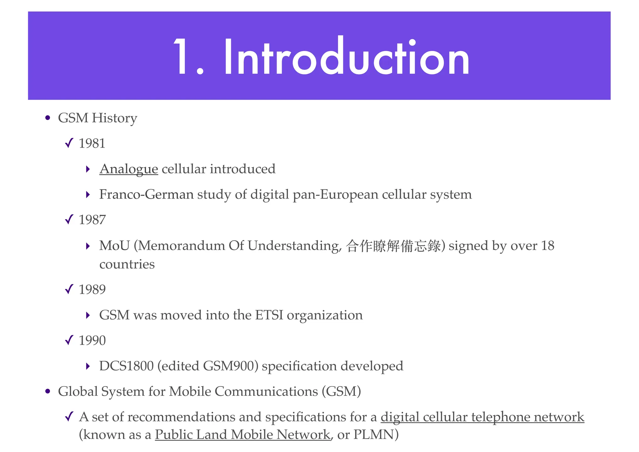
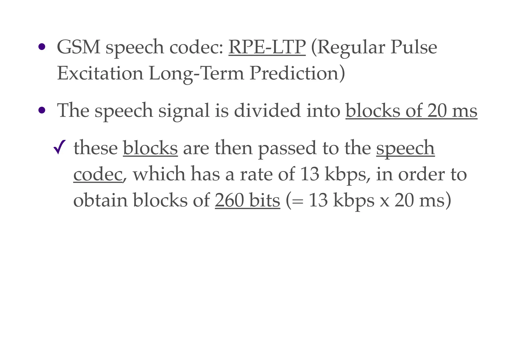
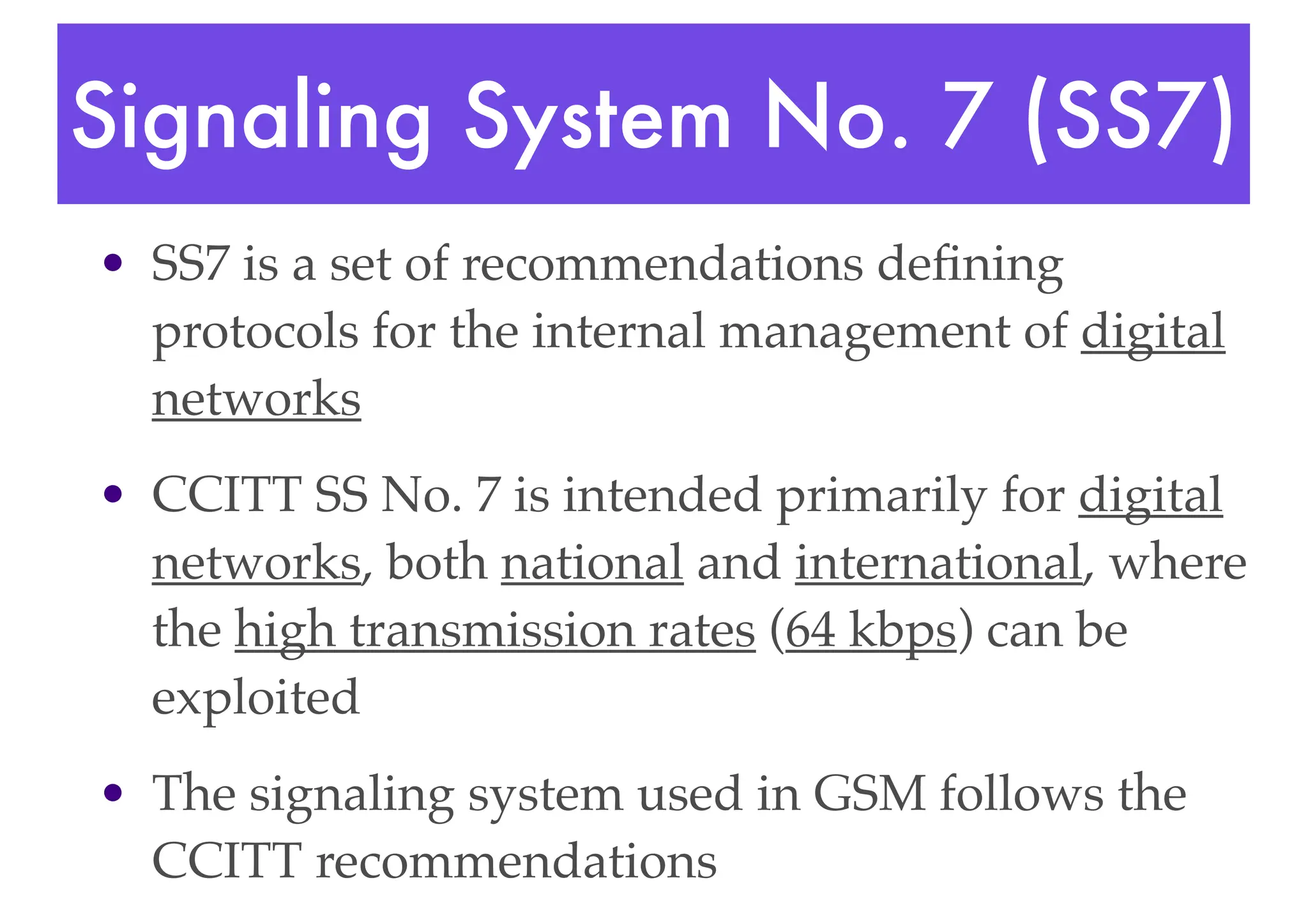
The document provides an overview of the Global System for Mobile Communications (GSM). Key points include:
- GSM is a digital cellular network developed to provide improved voice quality, capacity, and security compared to earlier analog networks.
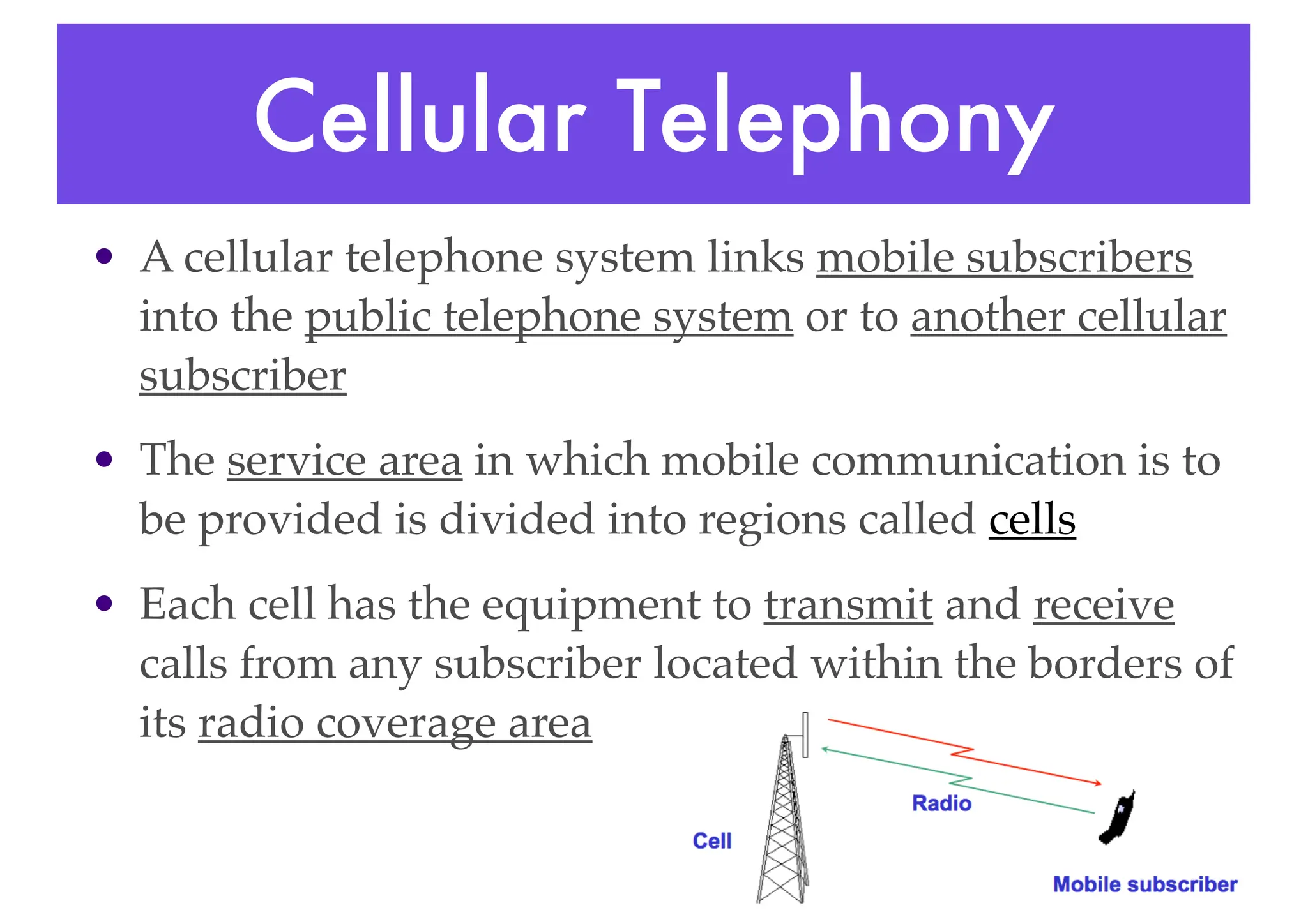
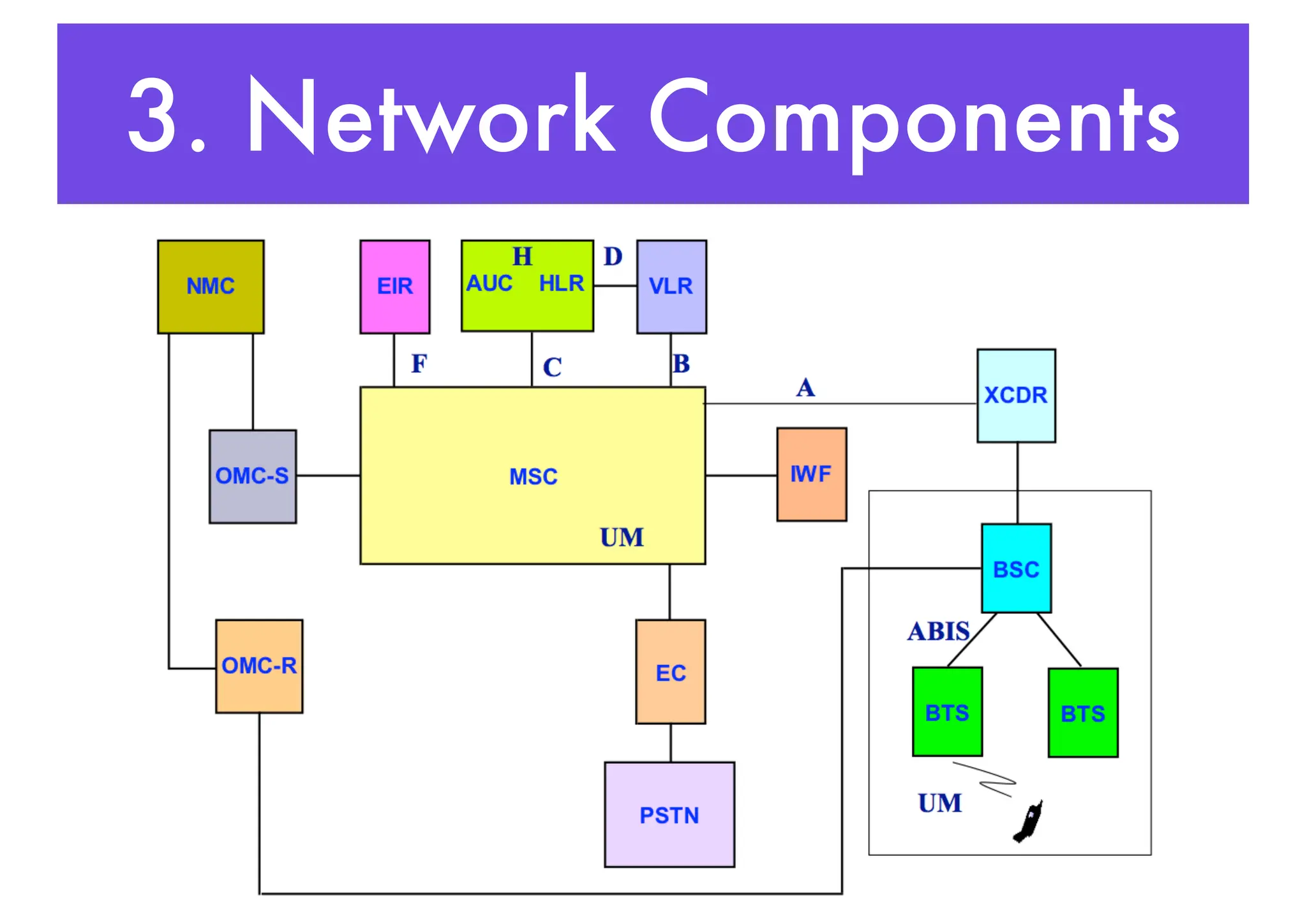
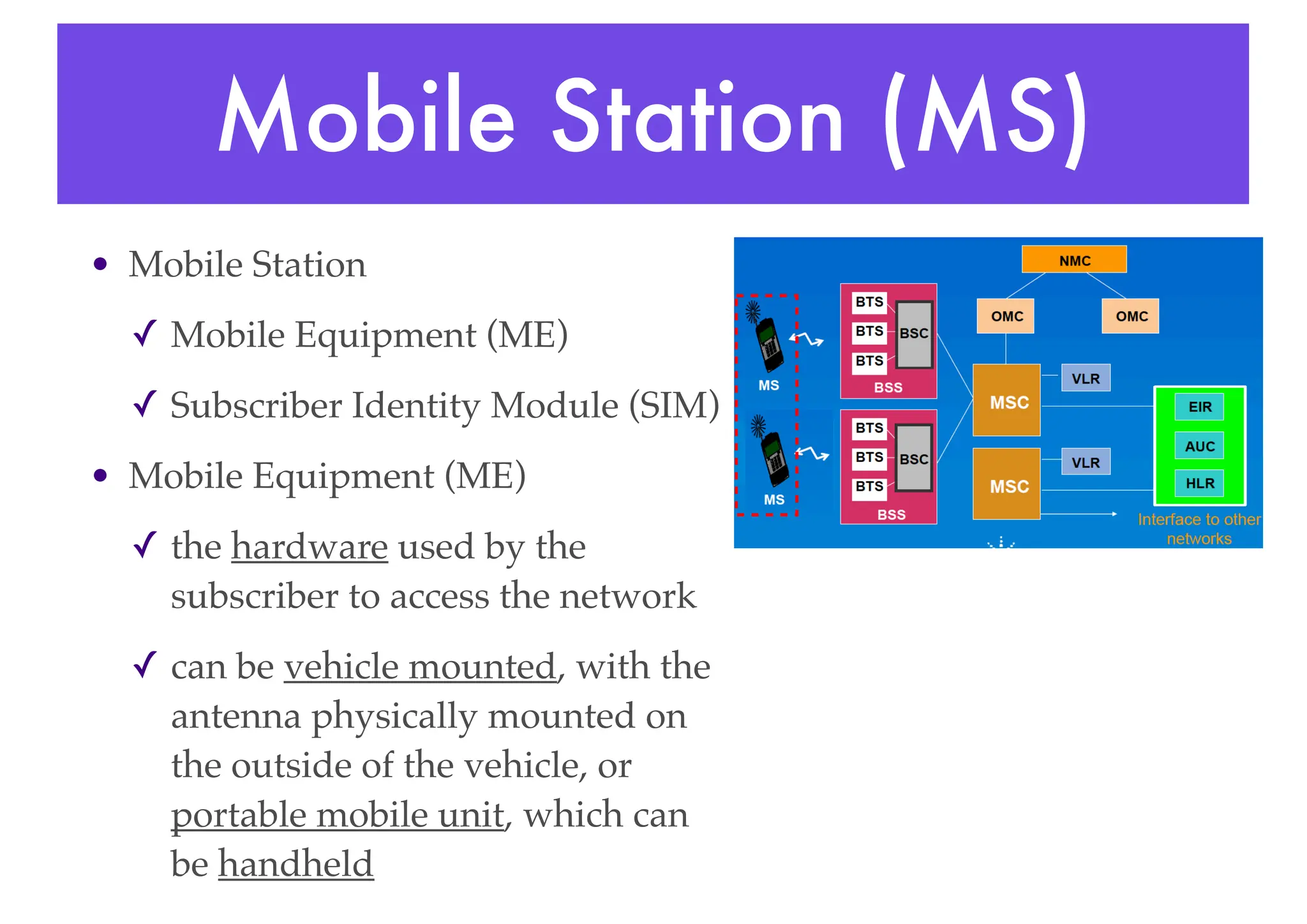
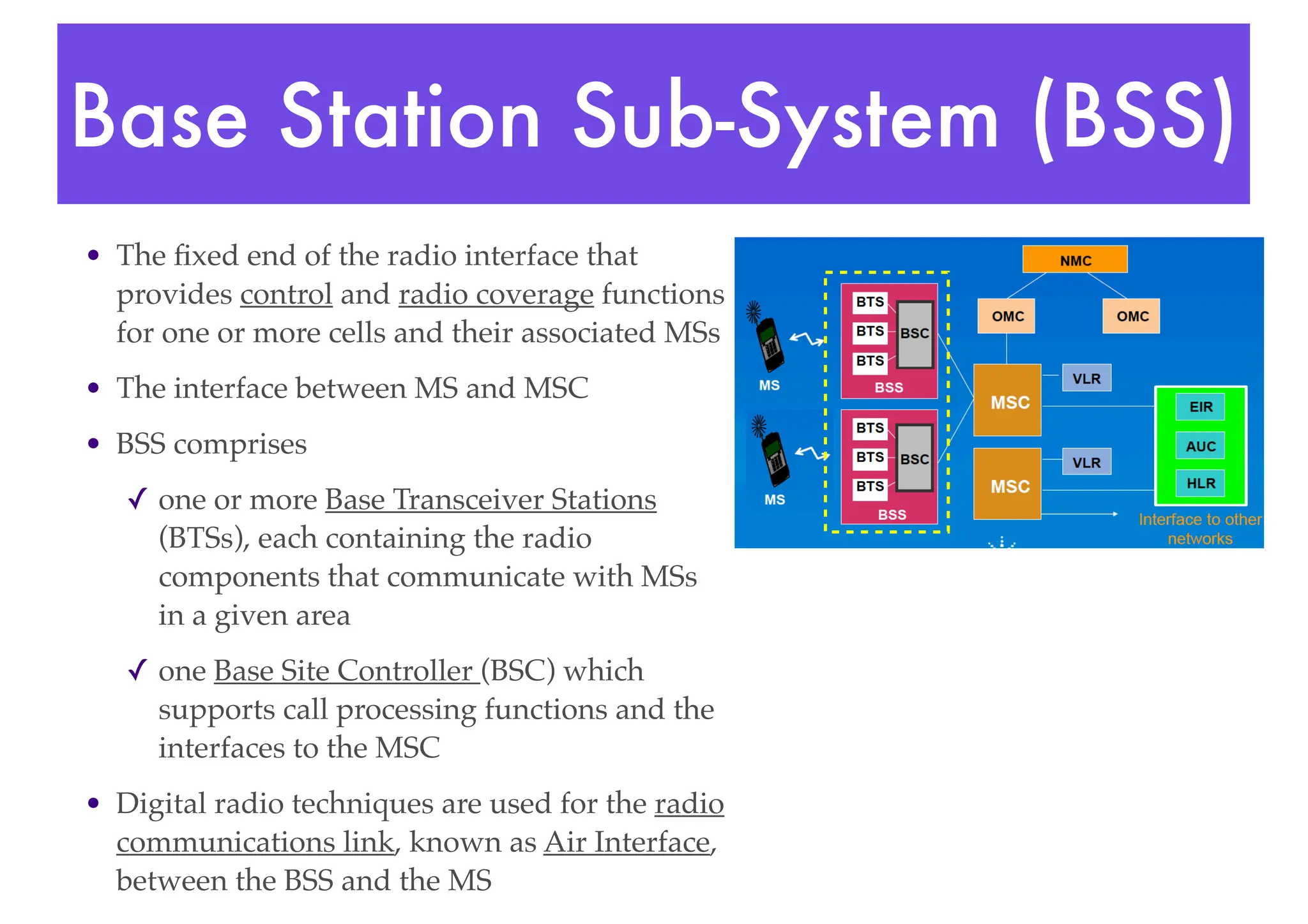
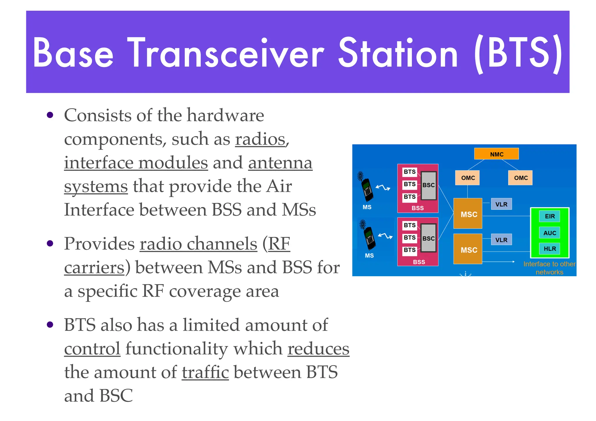
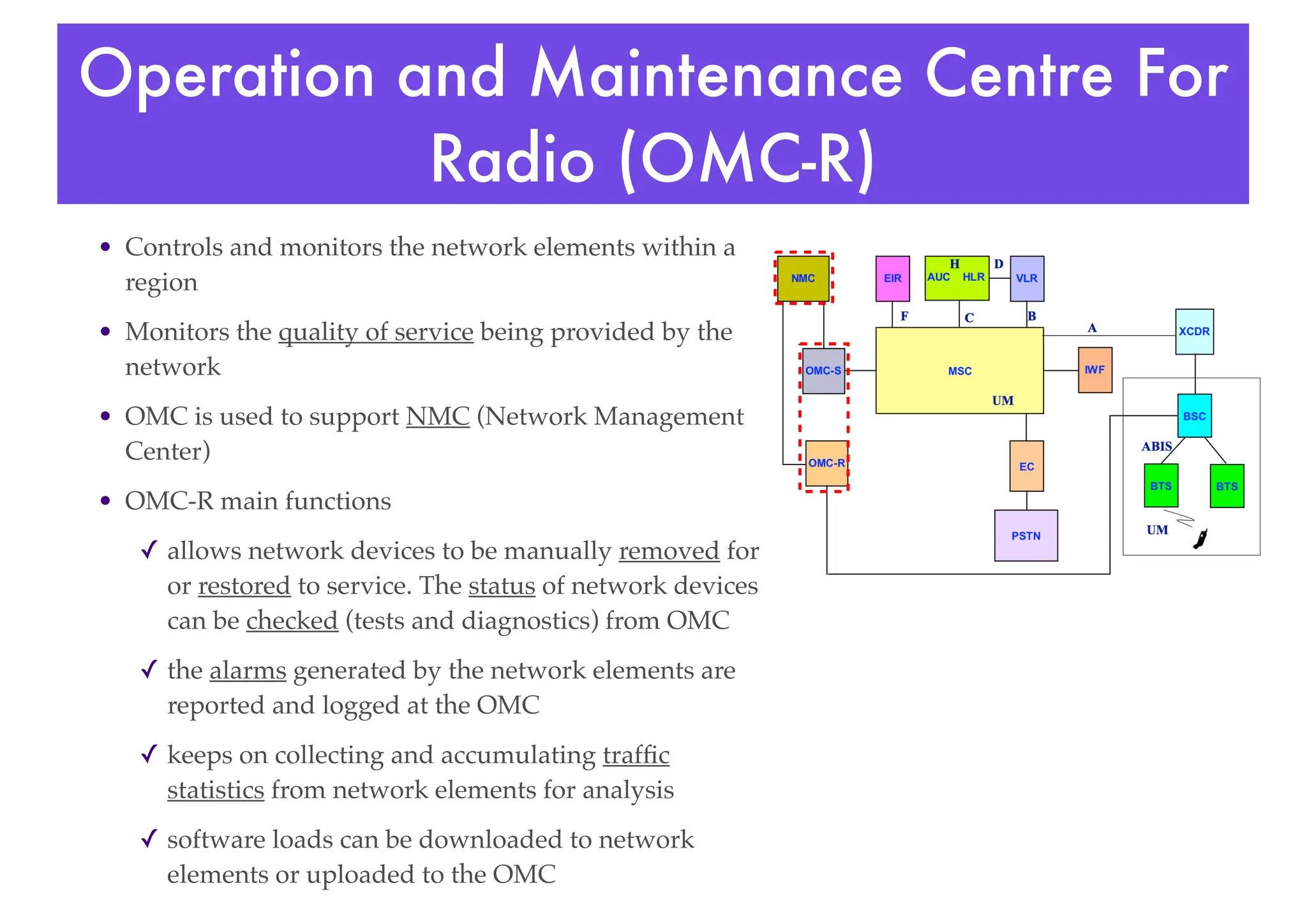
- The network uses a cell structure where each cell contains radio transmission equipment and is connected to switches that provide access to wired networks.
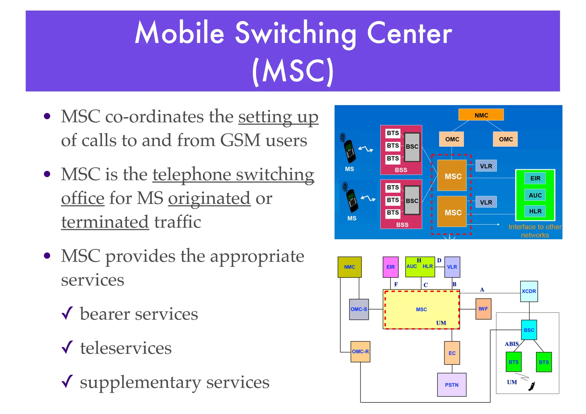
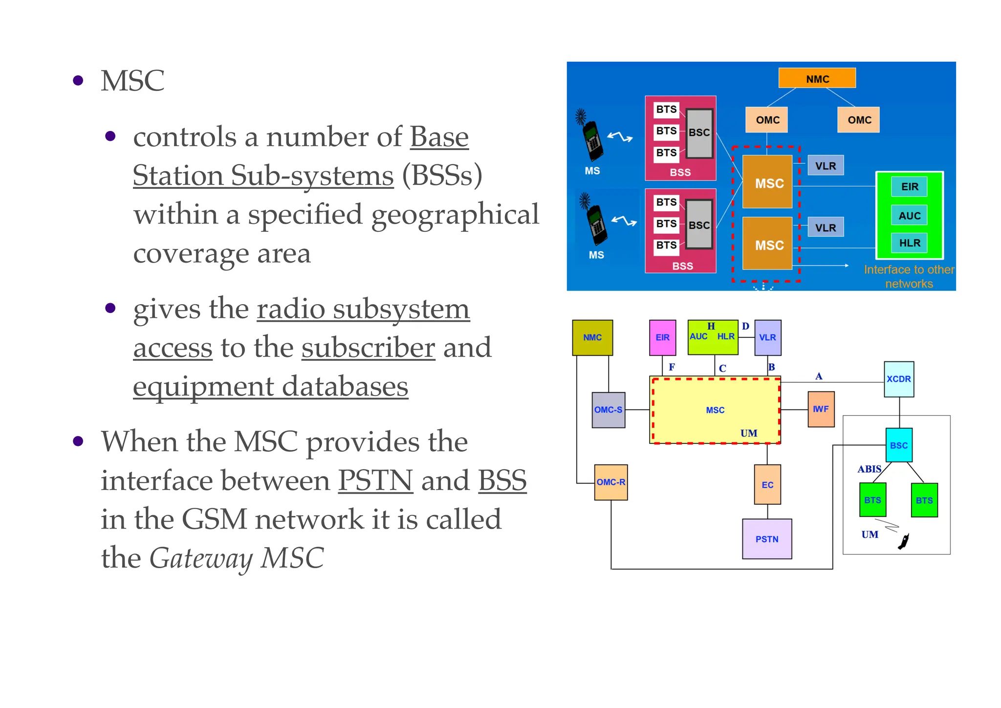
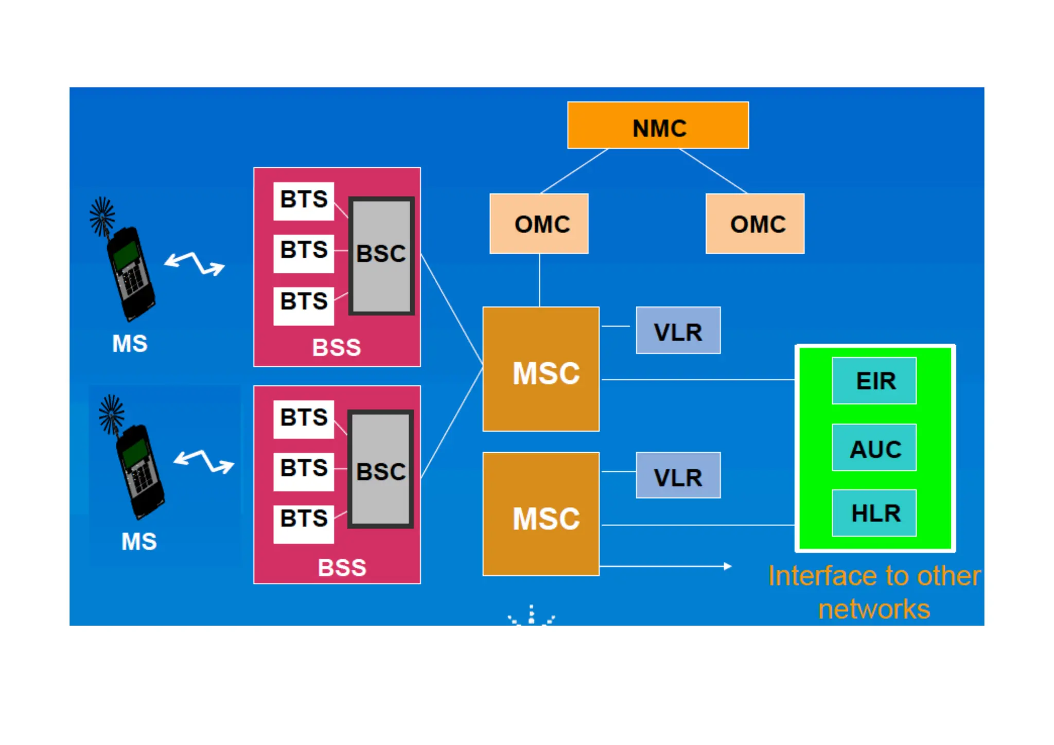
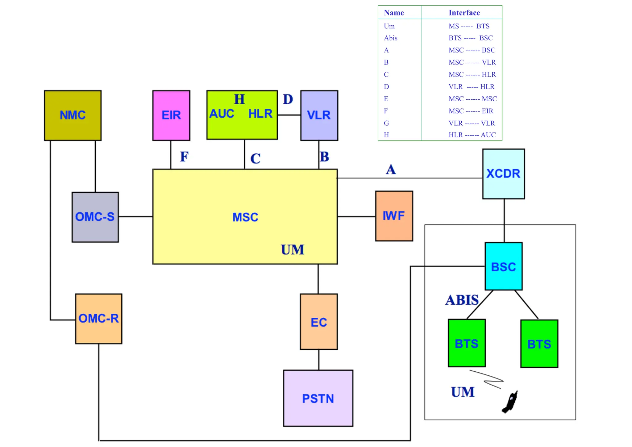
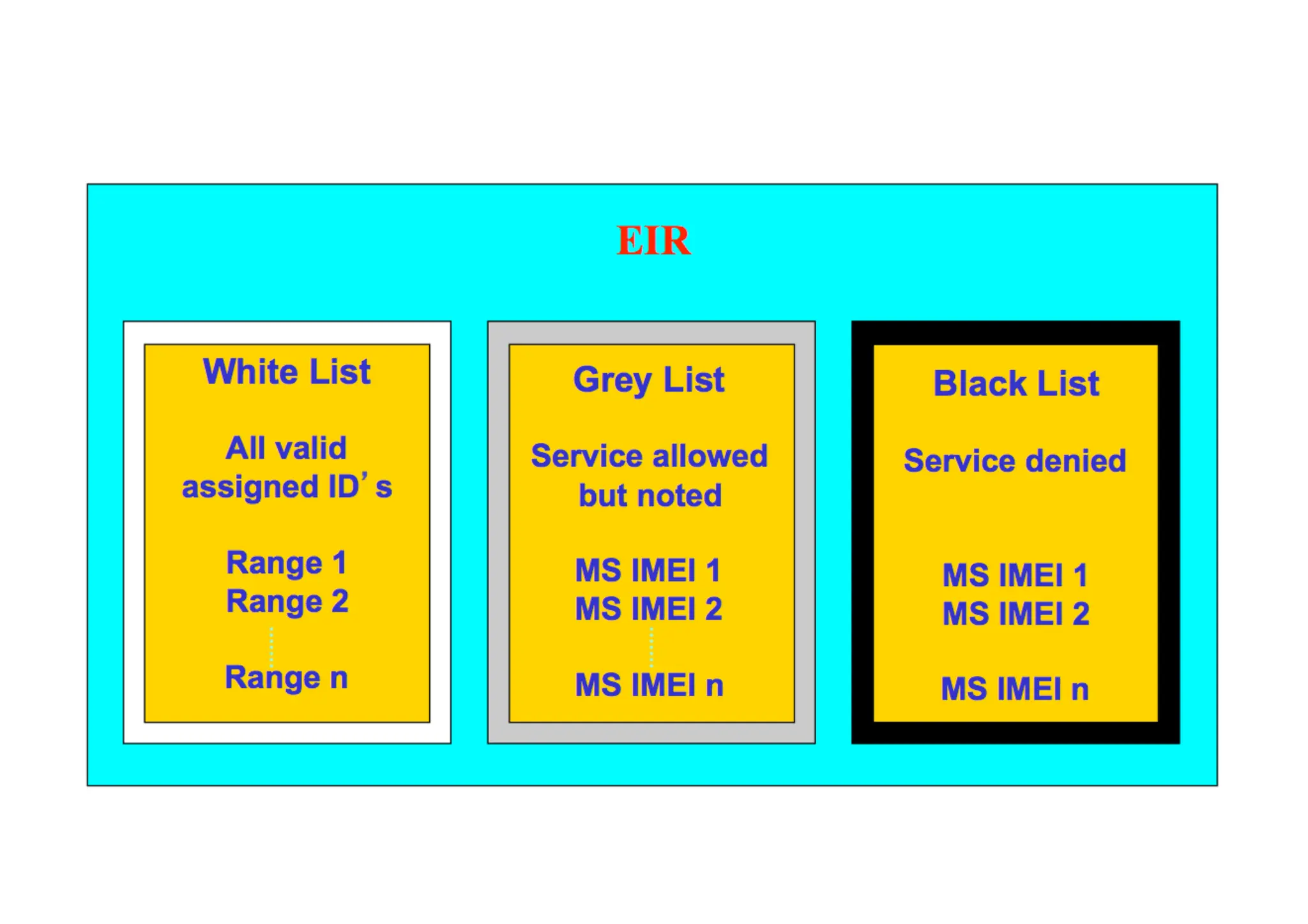
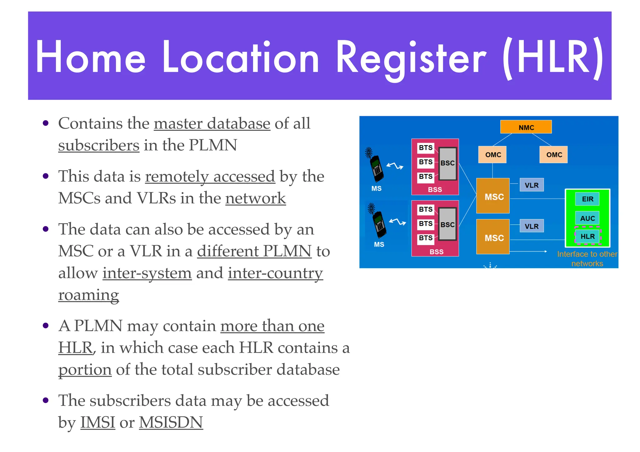
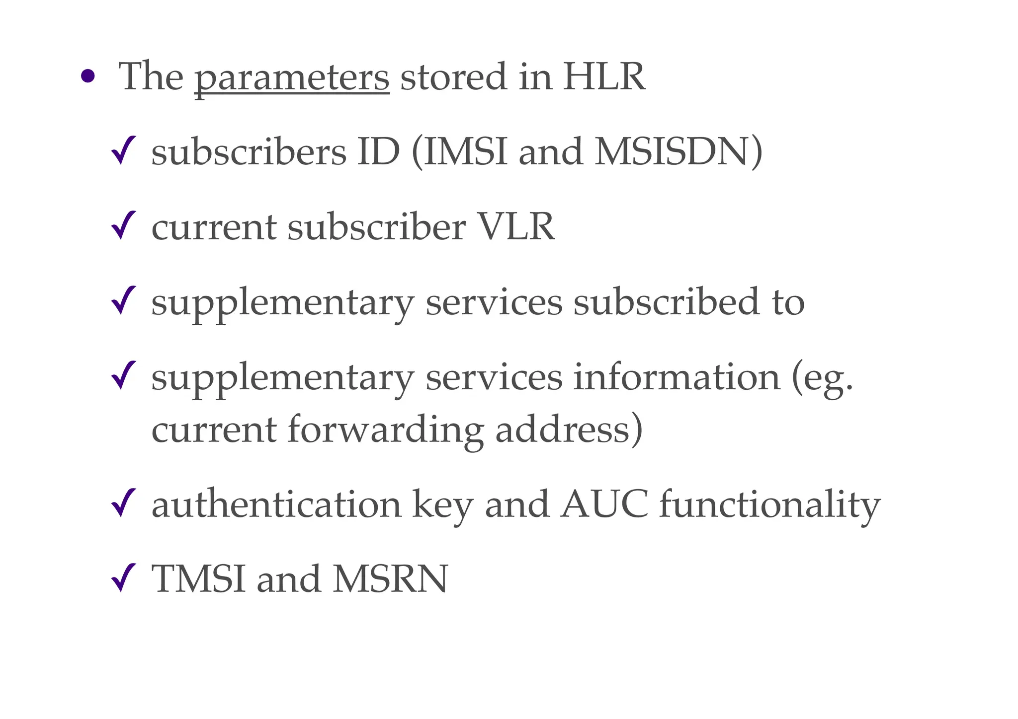
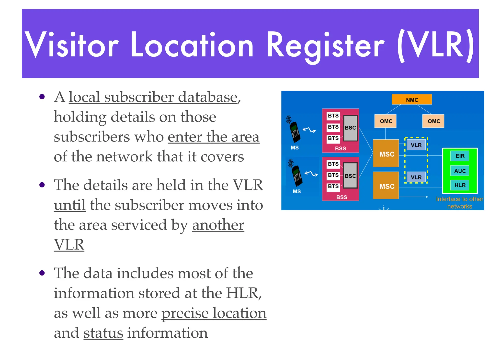
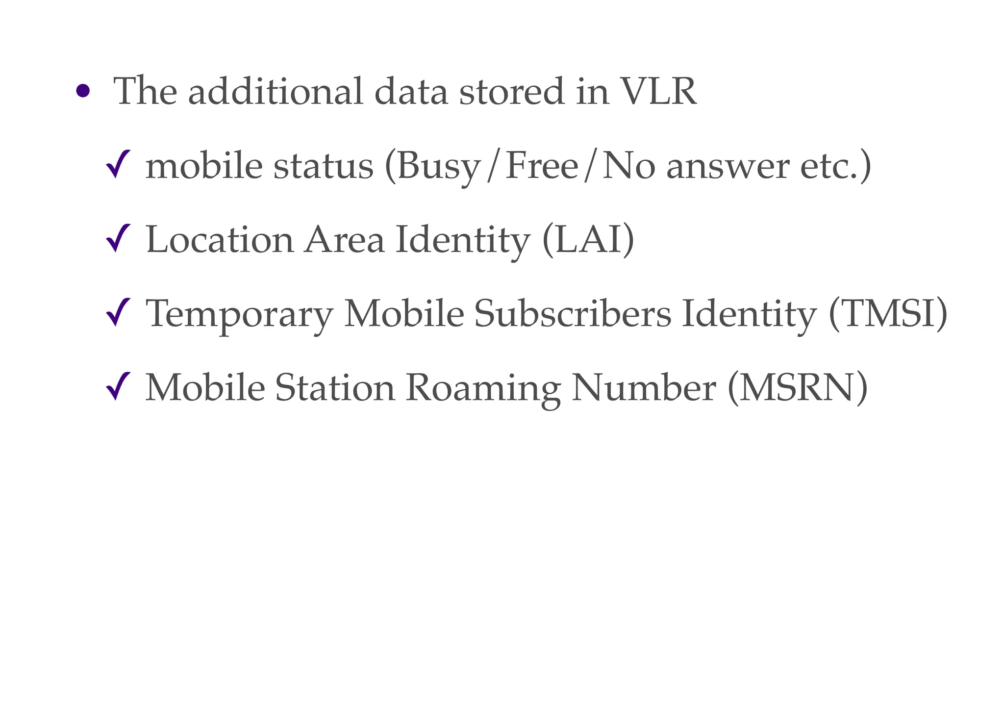
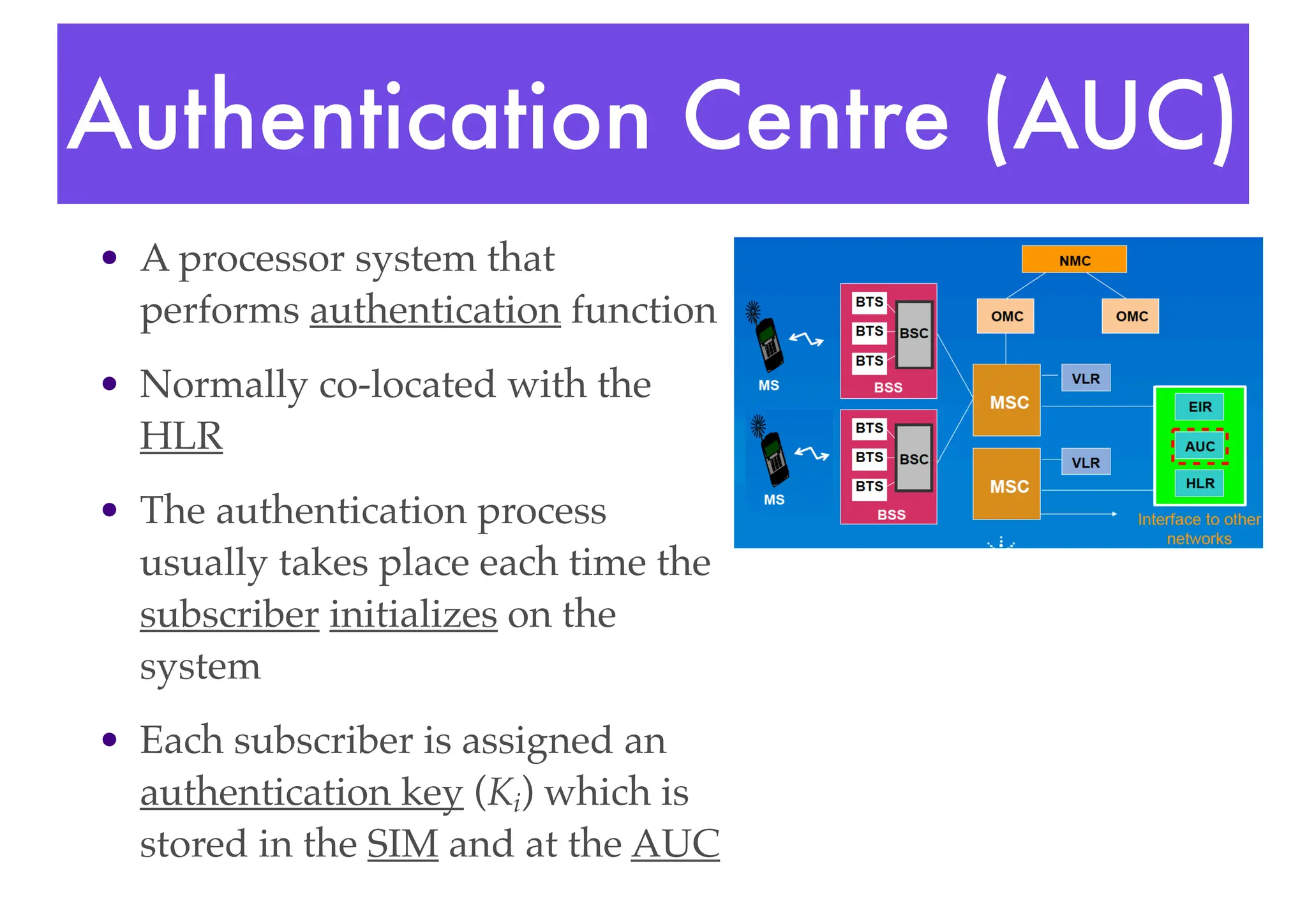
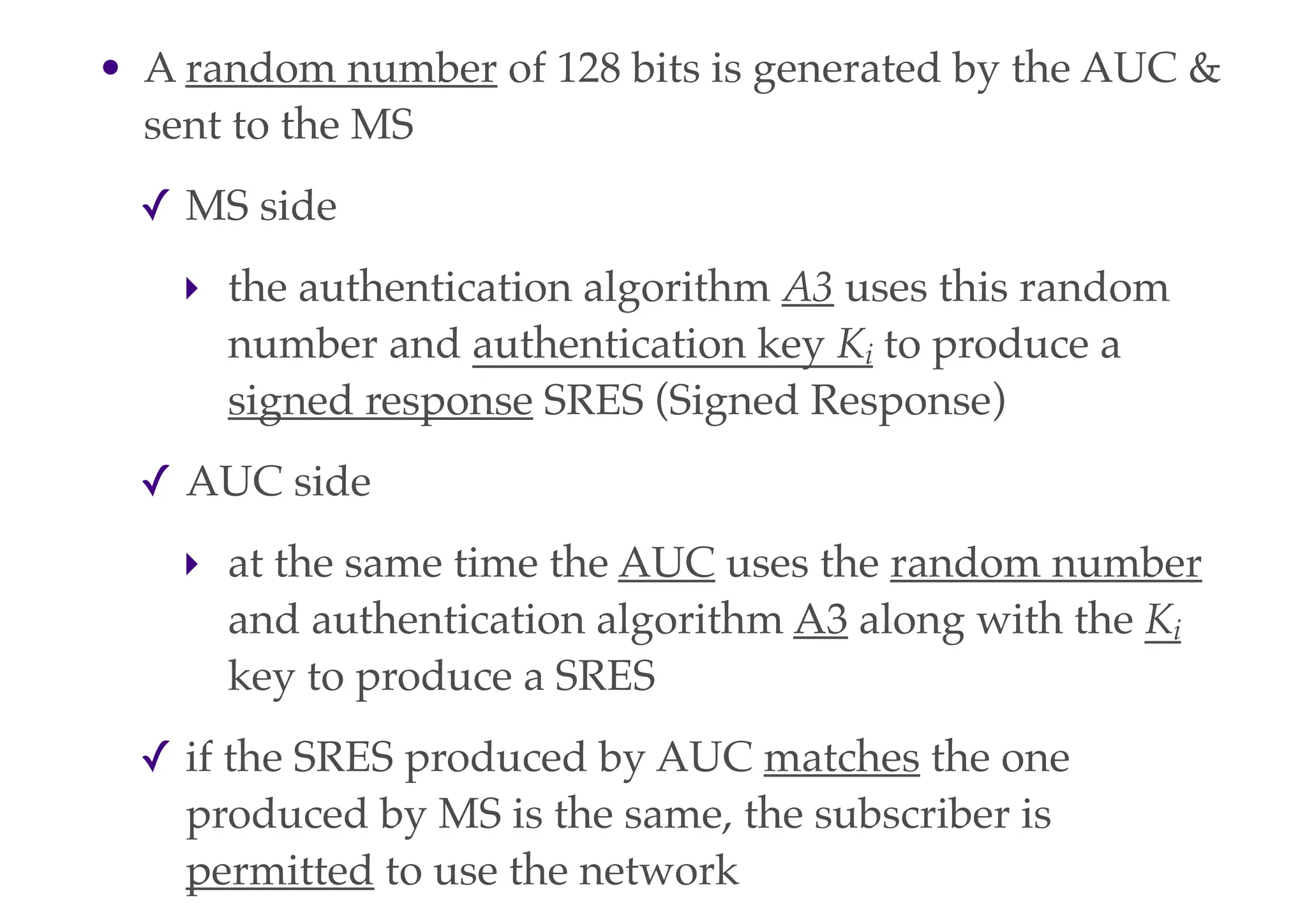
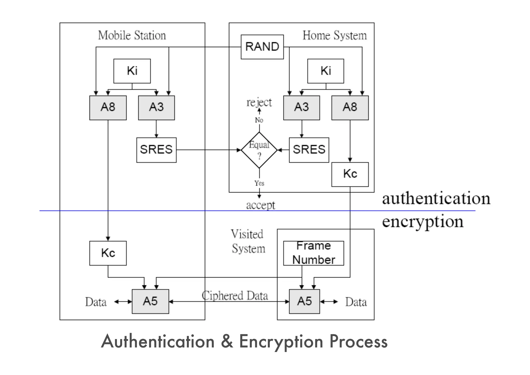
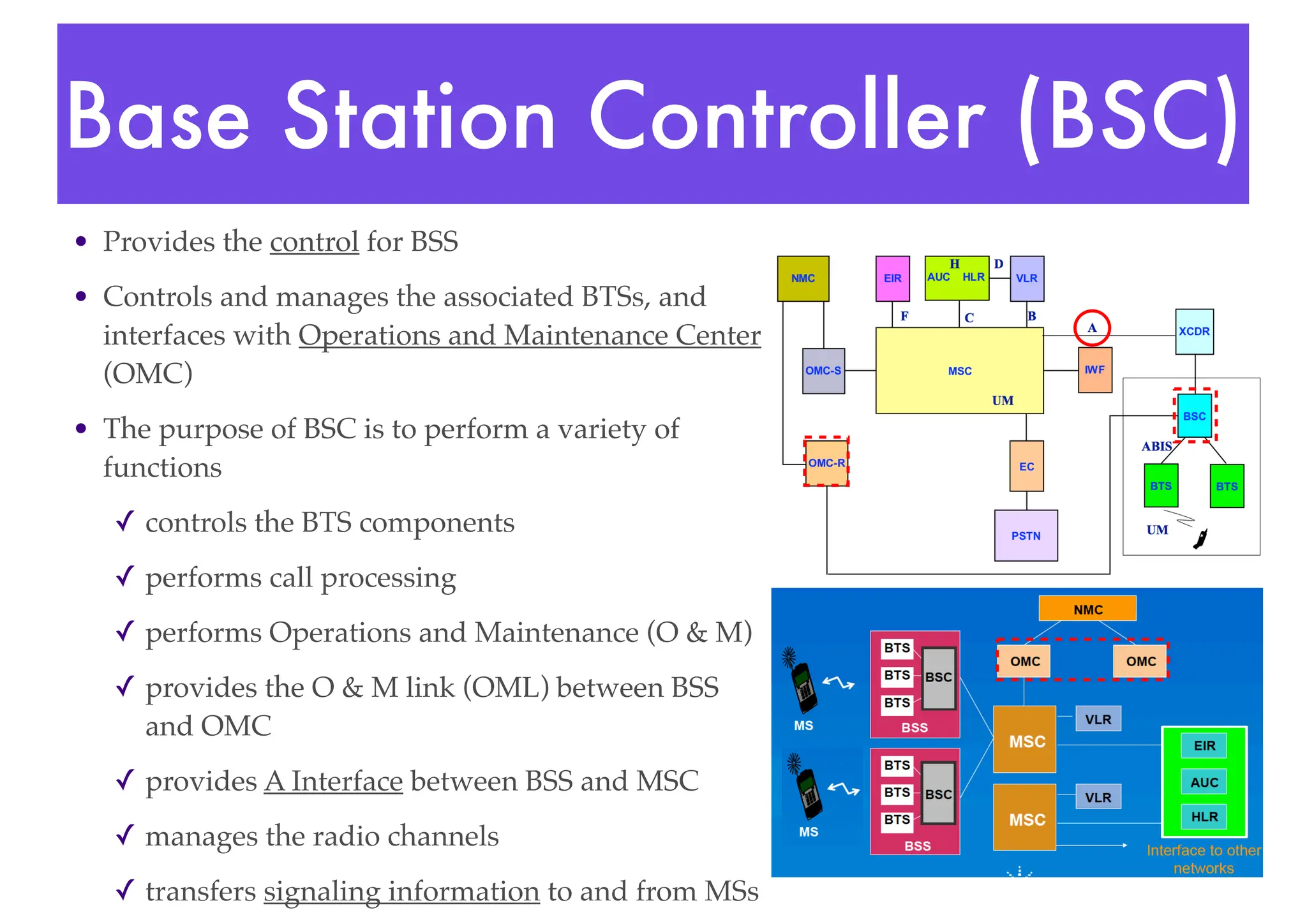
- Core network components include Mobile Switching Centers (MSCs), Home Location Registers (HLRs), Visitor Location Registers (VLRs), and Authentication Centers (AUCs) that manage subscriber data and authentication.
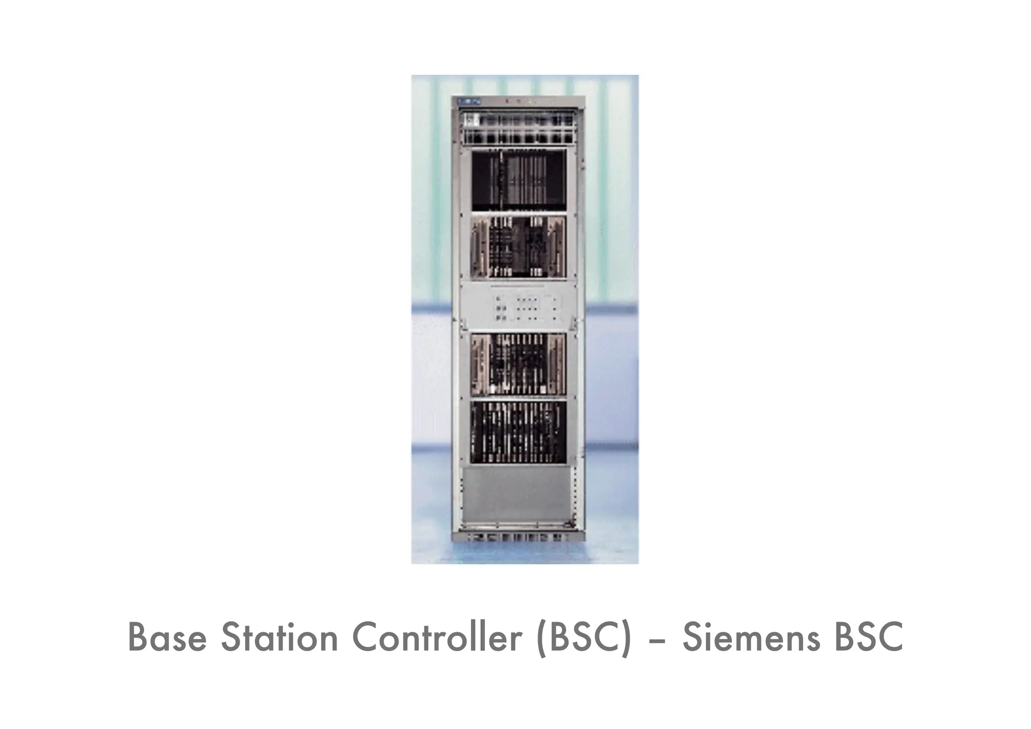
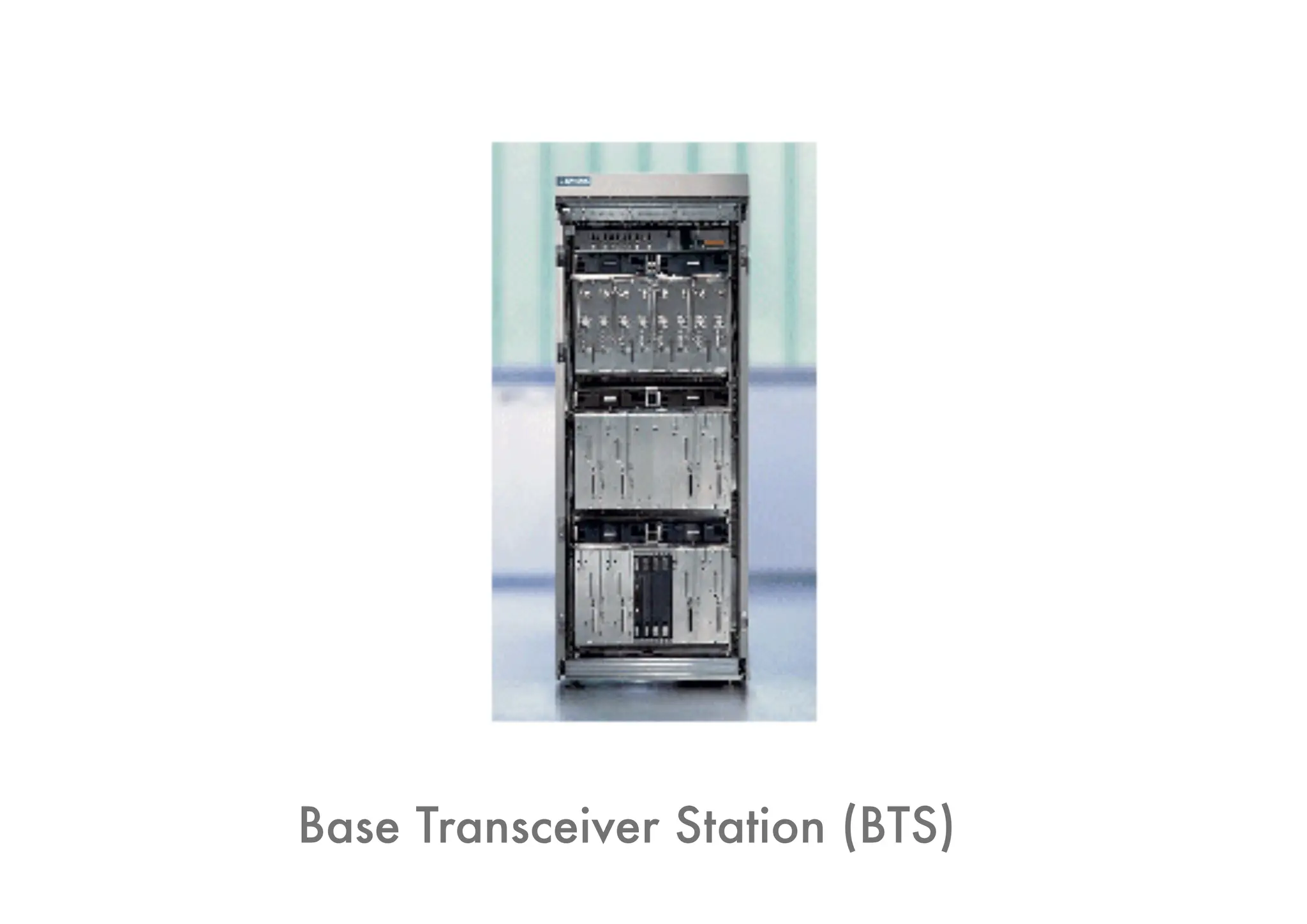
- Radio access is handled by Base Transceiver Stations (BTSs) and Base Station Controllers (BSCs)
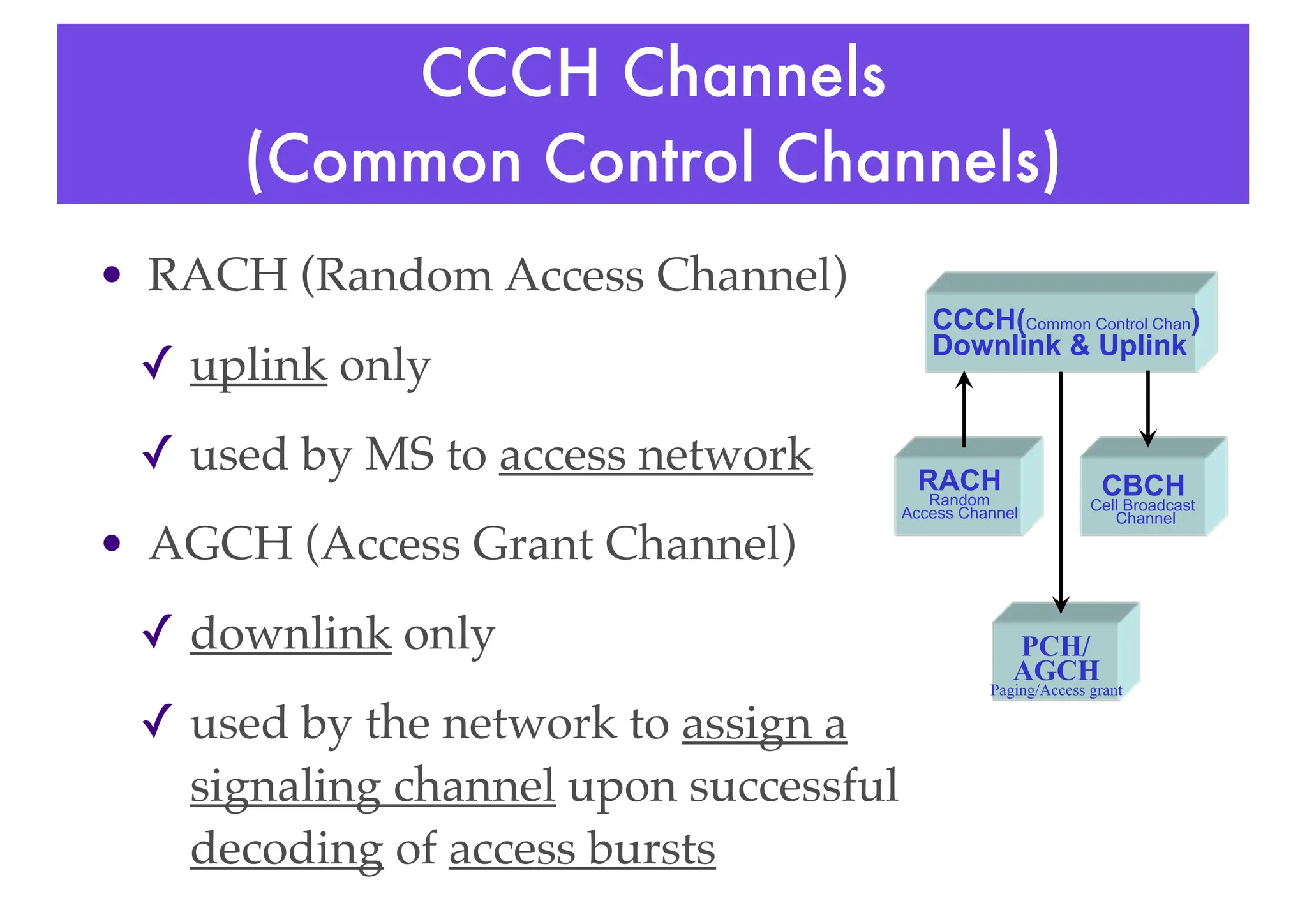
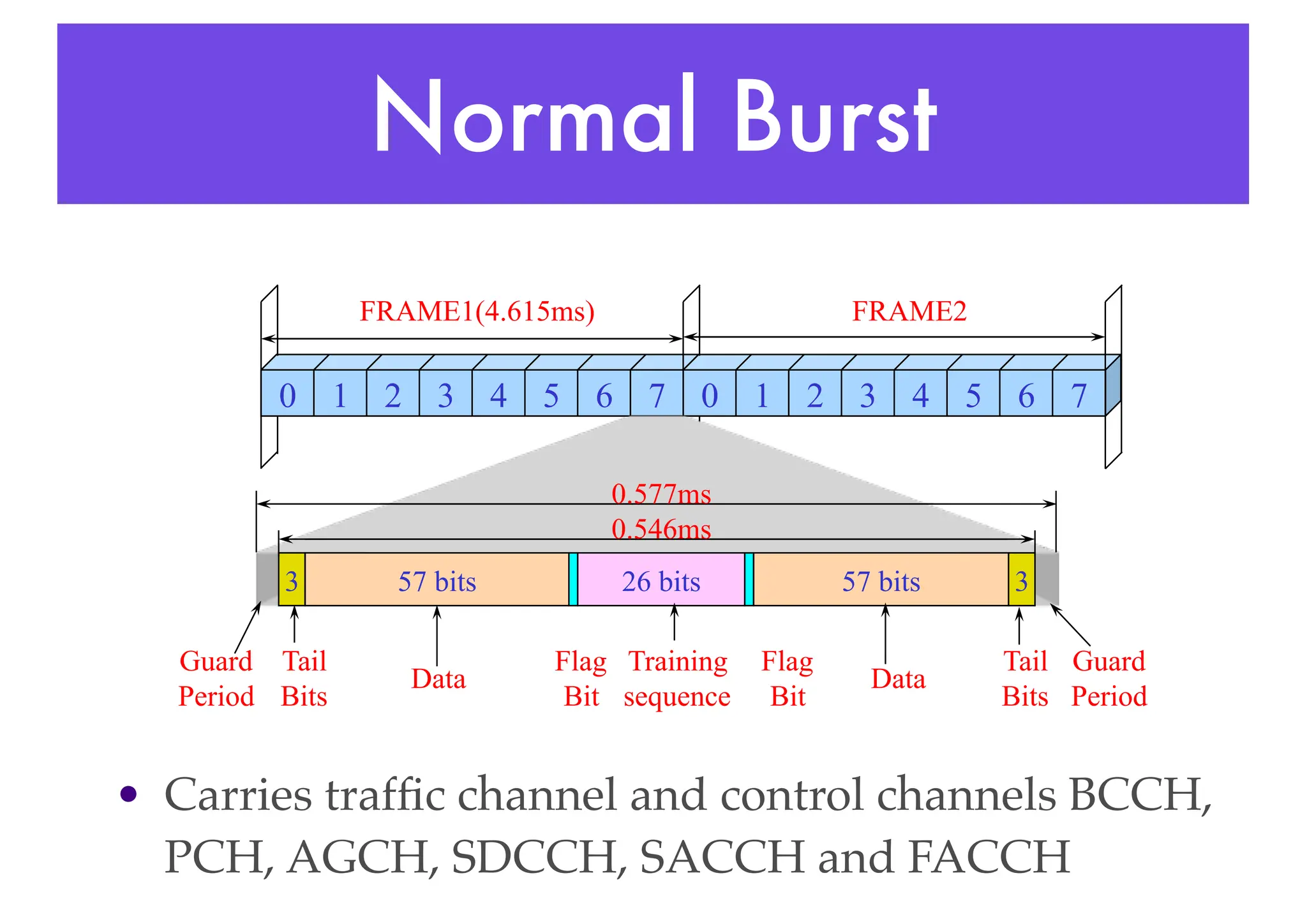
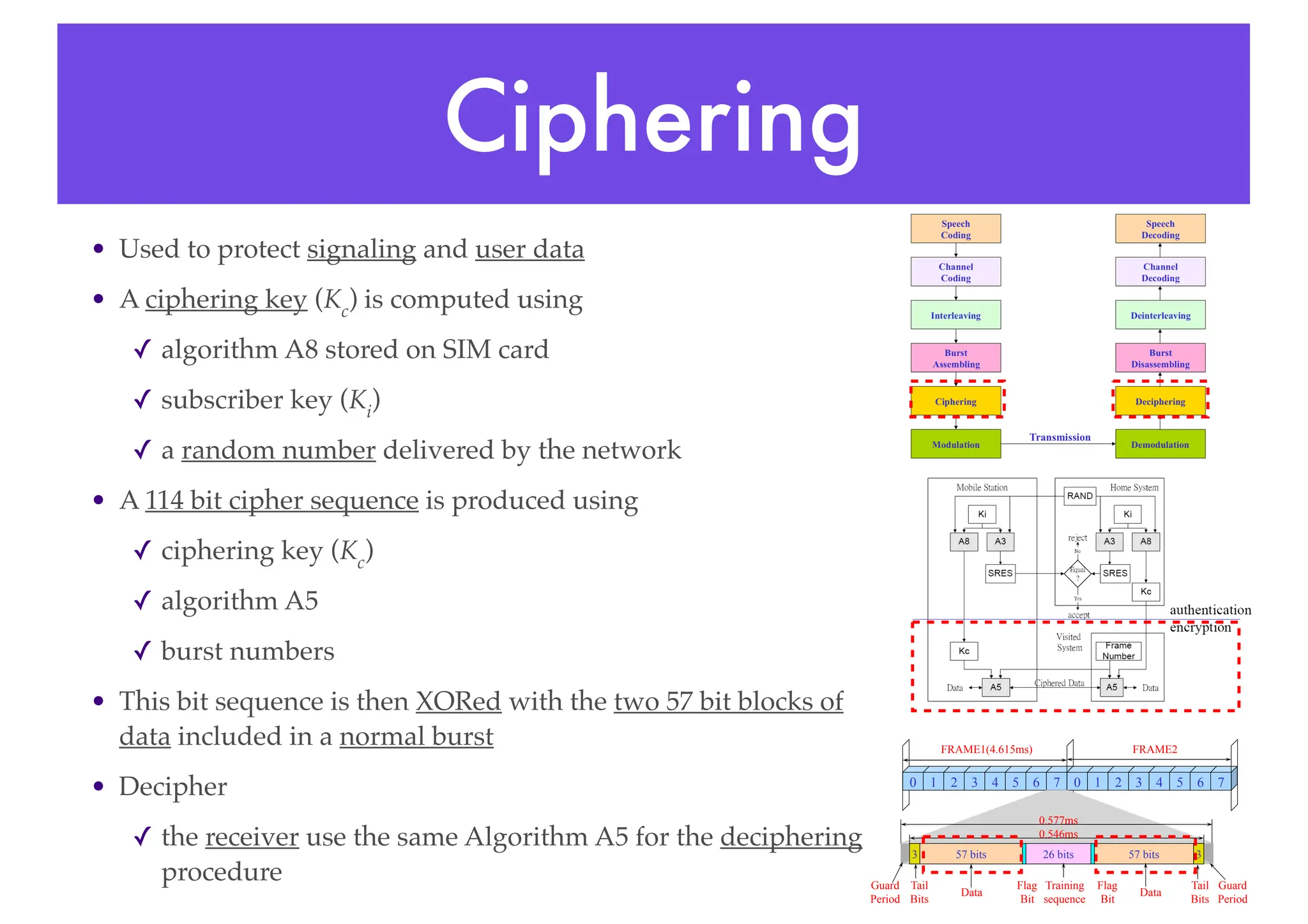
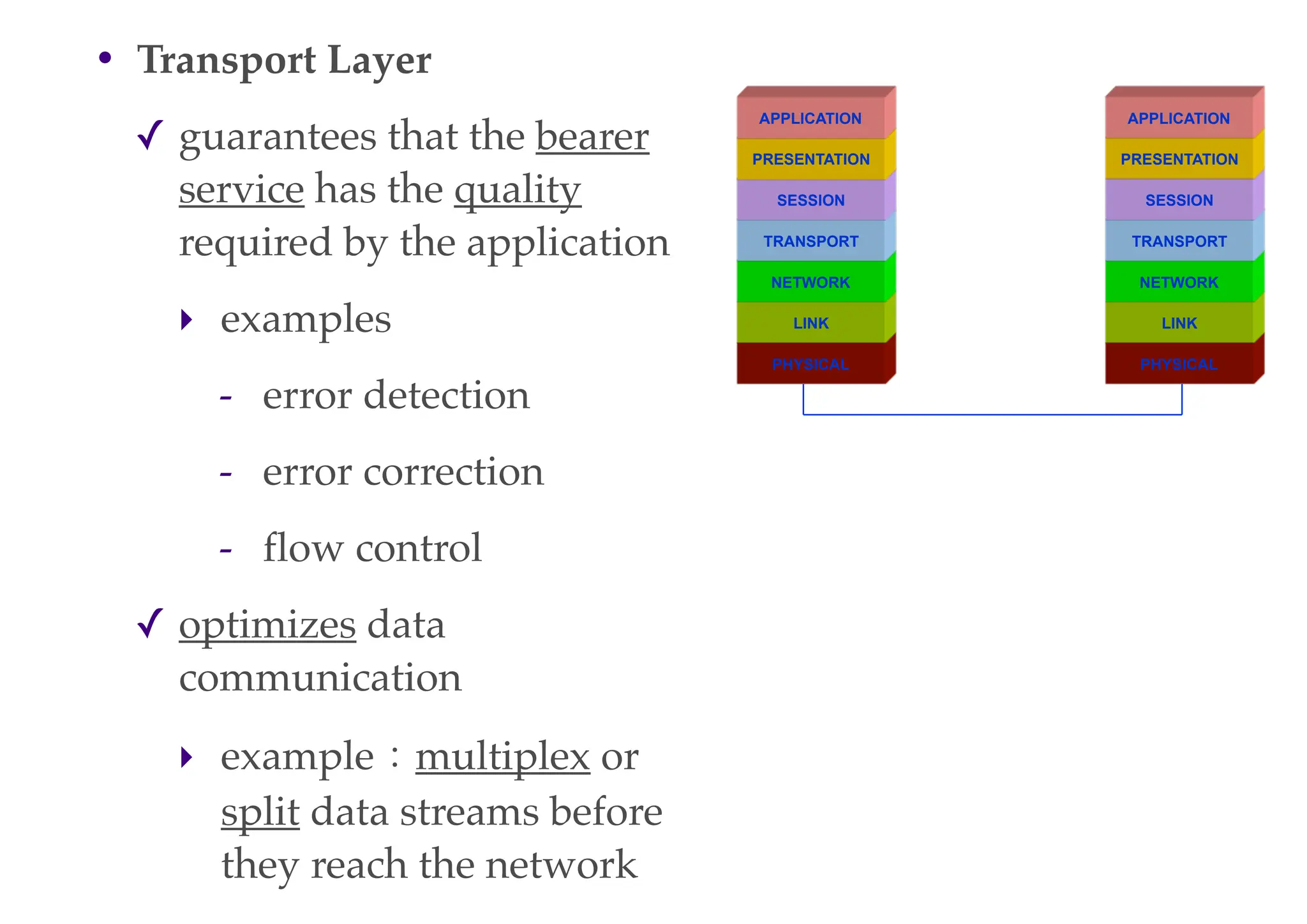
![• Flag bits
✓ this bit is used to indicate if the 57 bits
data block is used as FACCH (Fast
Associated Control Channel)
• Training Sequence
✓ a set sequence of bits known by both the
transmitter and the receiver (BCC of BSIC)
✓ when a burst of information is received
the equalizer searches for the training
sequence code
✓ the receiver measures and then mimics the
distortion which the signal has been
subjected to [受...影響]
✓ the receiver then compares the received
data with the distorted possible
transmitted sequence and chooses the
most likely one
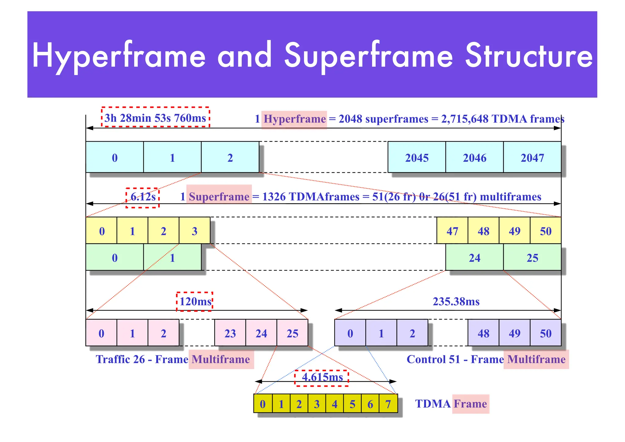
0 1 2 3 4 5 6 7 0 1 2 3 4 5 6 7
57 bits 57 bits
26 bits 3
3
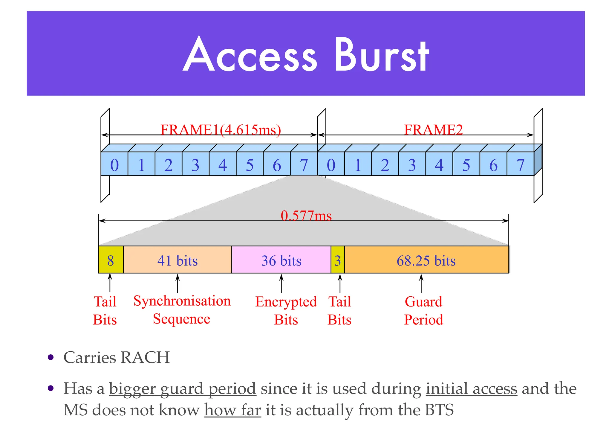
FRAME1(4.615ms) FRAME2
Training
sequence
Data Data
Tail
Bits
Tail
Bits
Flag
Bit
Flag
Bit
Guard
Period
Guard
Period
0.546ms
0.577ms
BCC:Base station Color Code
BSIC:Base Station Identity Code](https://image.slidesharecdn.com/globalsystemformobilecommunications1-240318191335-f6ac809a/75/Global-System-for-Mobile-Communications-1-pdf-62-2048.jpg)
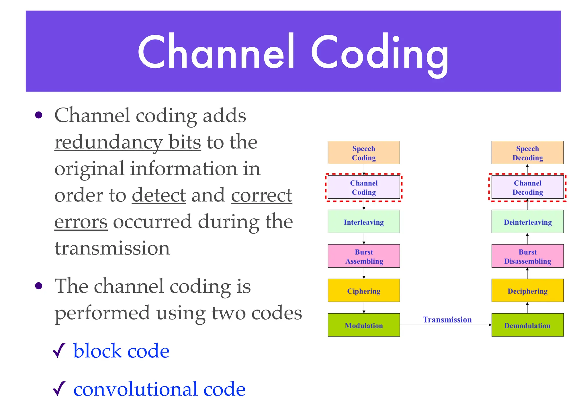
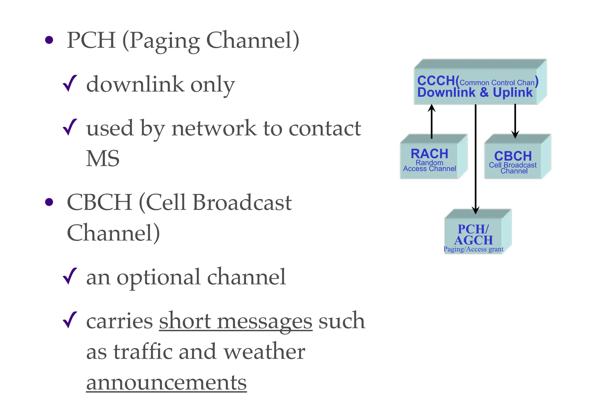
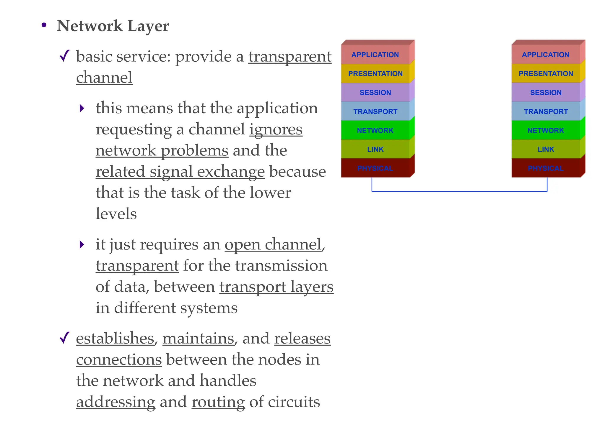
![• Block code
✓ receives an input block of 240 bits and adds four
zero tail bits at the end of the input block
✓ the output of the block code is consequently a block
of 244 bits
✓ every block codes submit k bits in their inputs and
forwards n bits in their output [known as (n,k) code]
• Convolutional code
✓ adds redundancy bits in order to protect the
information
✓ a convolutional encoder contains memory
✓ this property differentiates a convolutional code
from a block code
✓ every convolutional code uses m units of memory
[known as (n,k,m) code]](https://image.slidesharecdn.com/globalsystemformobilecommunications1-240318191335-f6ac809a/75/Global-System-for-Mobile-Communications-1-pdf-75-2048.jpg)
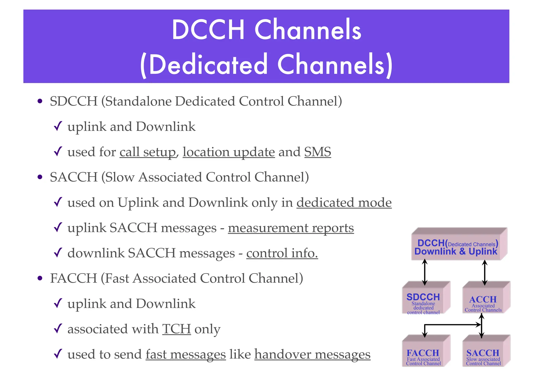
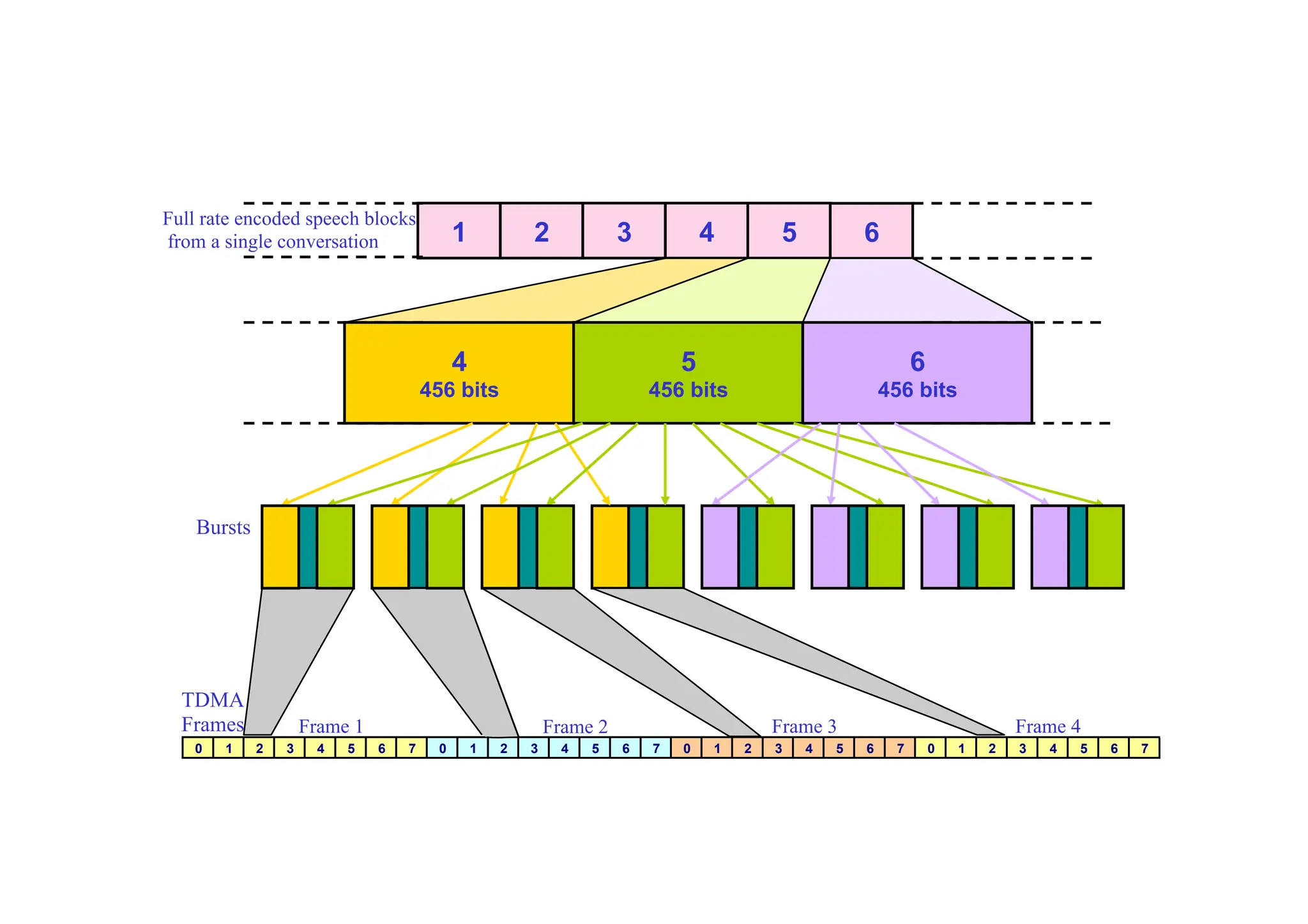
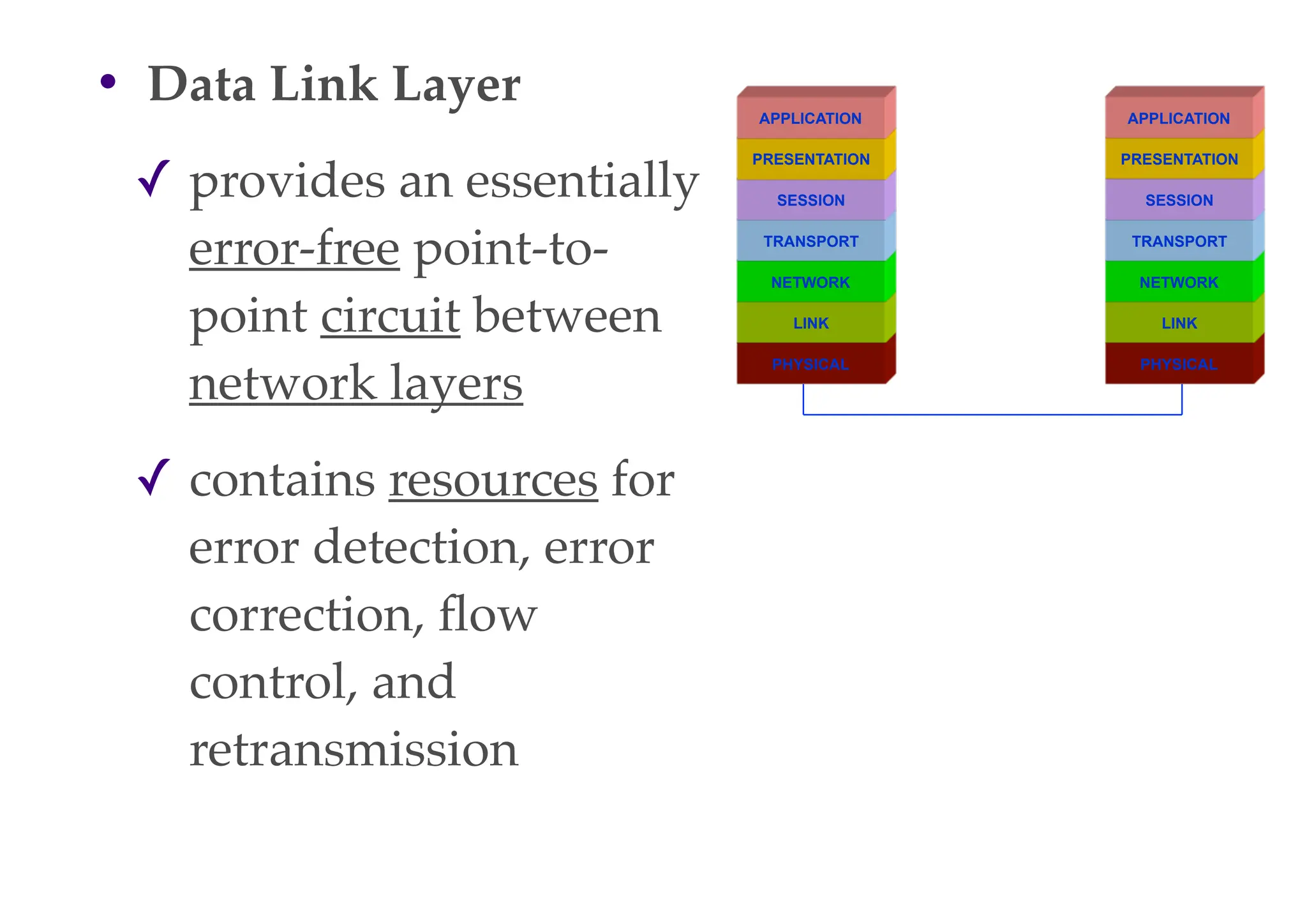
![Interleaving
• An interleaving rearranges a group of
bits in a particular way
• It is used in combination with FEC
codes (Forward Error Correction
Codes) in order to improve the
performance of error correction
mechanisms
• The interleaving decreases the
possibility of losing whole bursts
during the transmission, by
dispersing [分散] the errors
• As the errors are less concentrated, it
is then easier to correct them](https://image.slidesharecdn.com/globalsystemformobilecommunications1-240318191335-f6ac809a/75/Global-System-for-Mobile-Communications-1-pdf-76-2048.jpg)

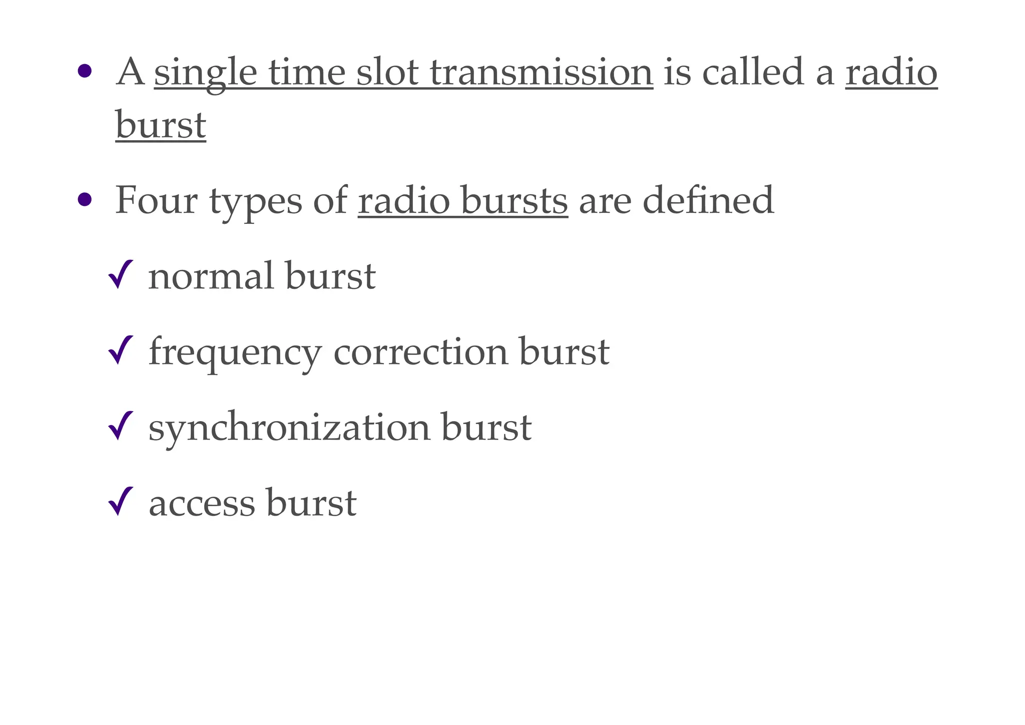
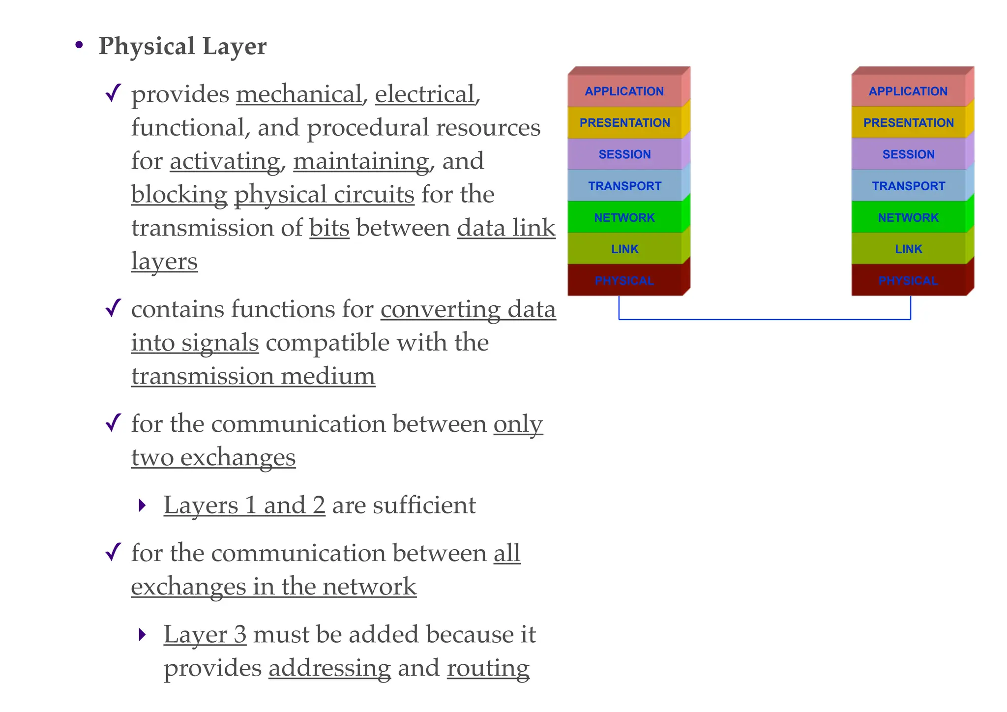
![• Dialed digits can be sent in two different ways
✓ decadic [⼗〸十進位] pulses (used for old-type rotary-
dial telephones), or
✓ combination of two tones (used for modern
pushbutton telephones) - Dual Tone Multi
Frequency (DTMF)
• Information tones (dial tone, ringing tone, busy
tone, etc.)
✓ the audio signals used to keep the calling party
(the A-subscriber) informed about what is going
on in the network during the set-up of a call](https://image.slidesharecdn.com/globalsystemformobilecommunications1-240318191335-f6ac809a/75/Global-System-for-Mobile-Communications-1-pdf-89-2048.jpg)
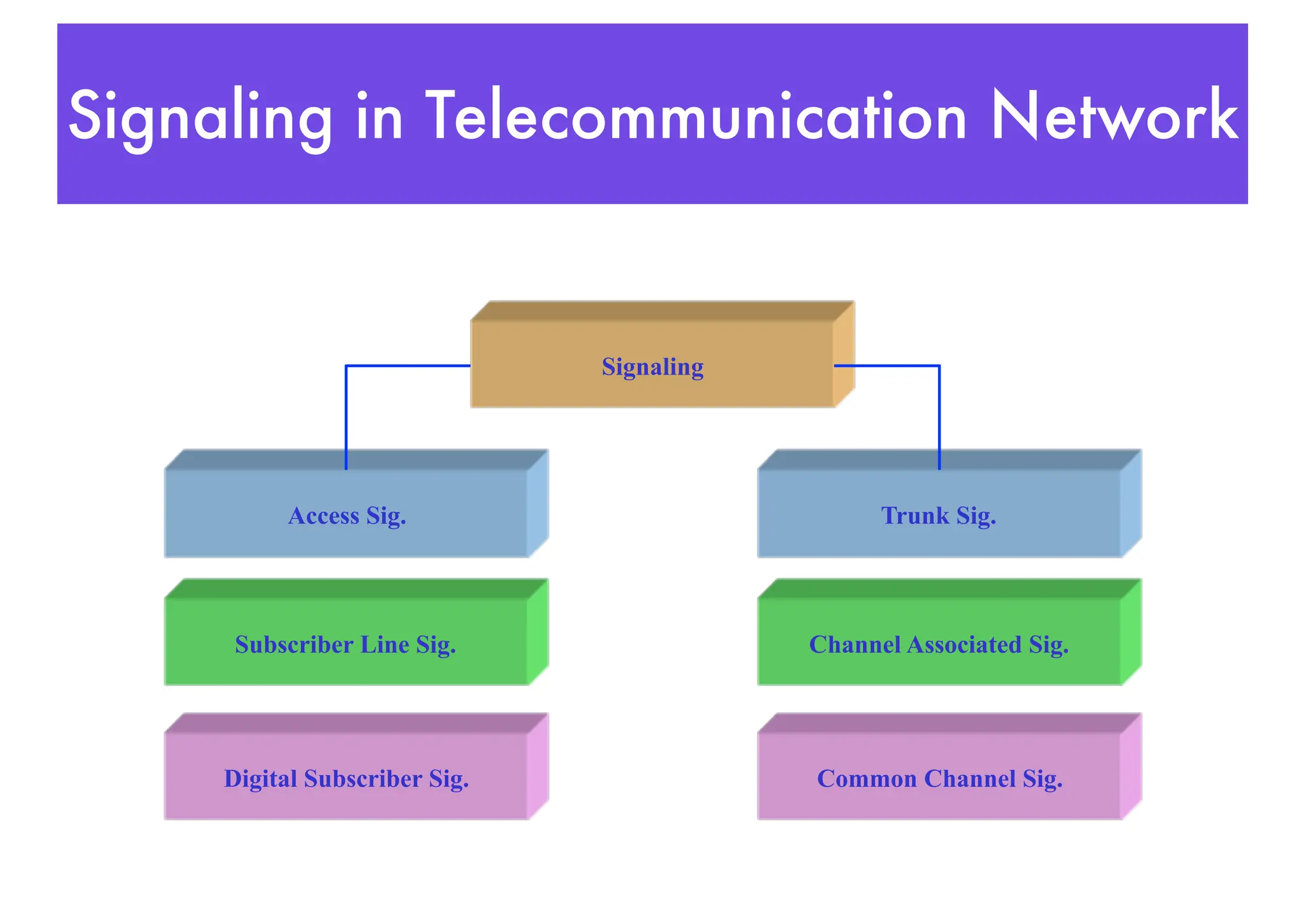
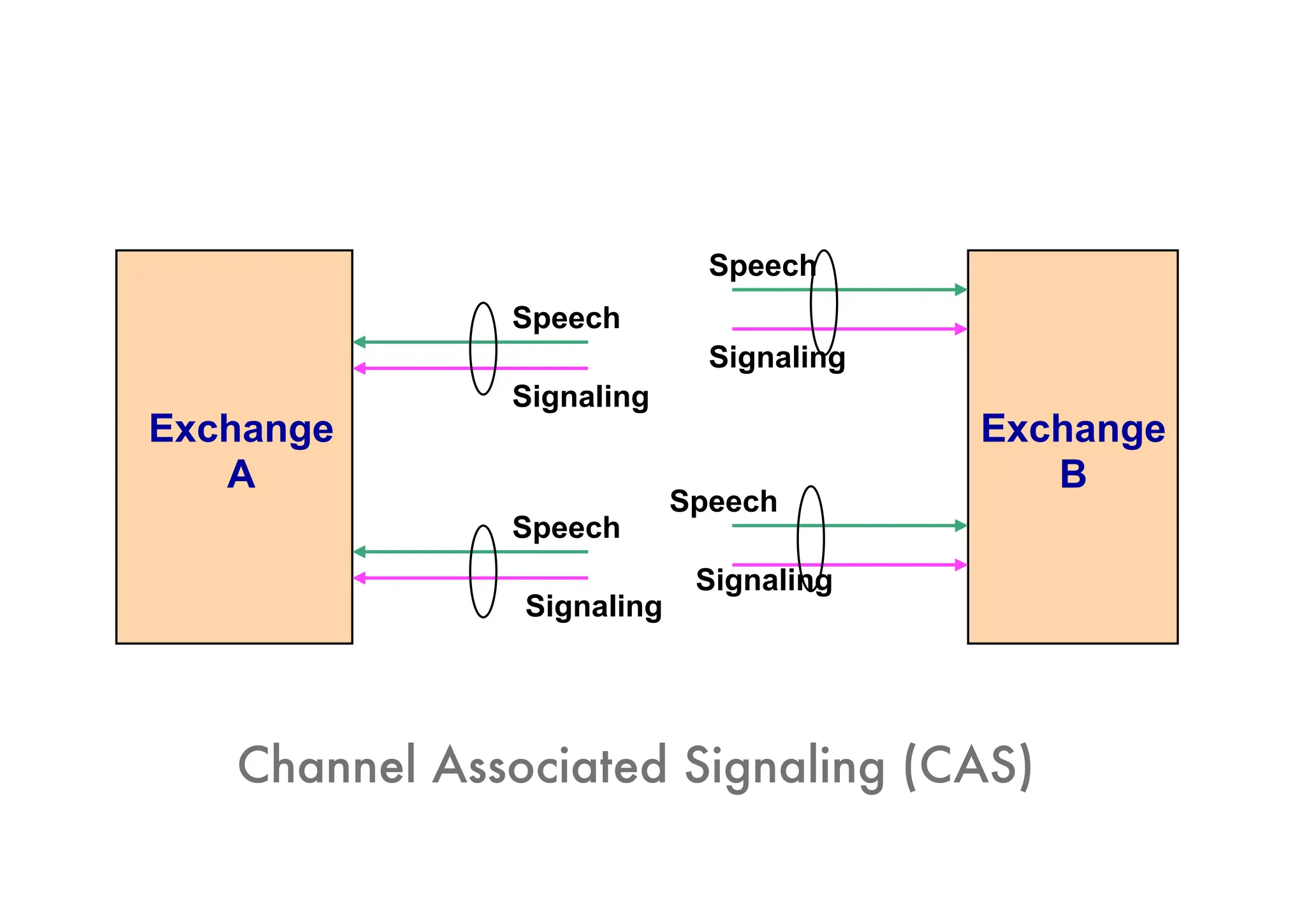
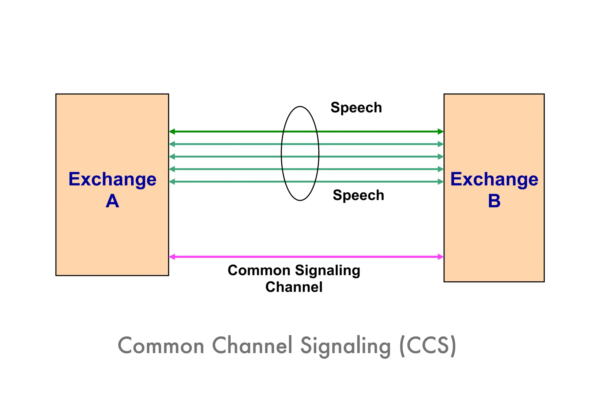
![Trunk Signaling
• Trunk signaling is inter-exchange
signaling information
• Two commonly used methods for
inter exchange signaling
✓ Channel Associated Signaling
(CAS)
‣ the signaling is always sent on
the same connection (PCM link)
as the traffic
‣ signaling is associated with the
traffic channel
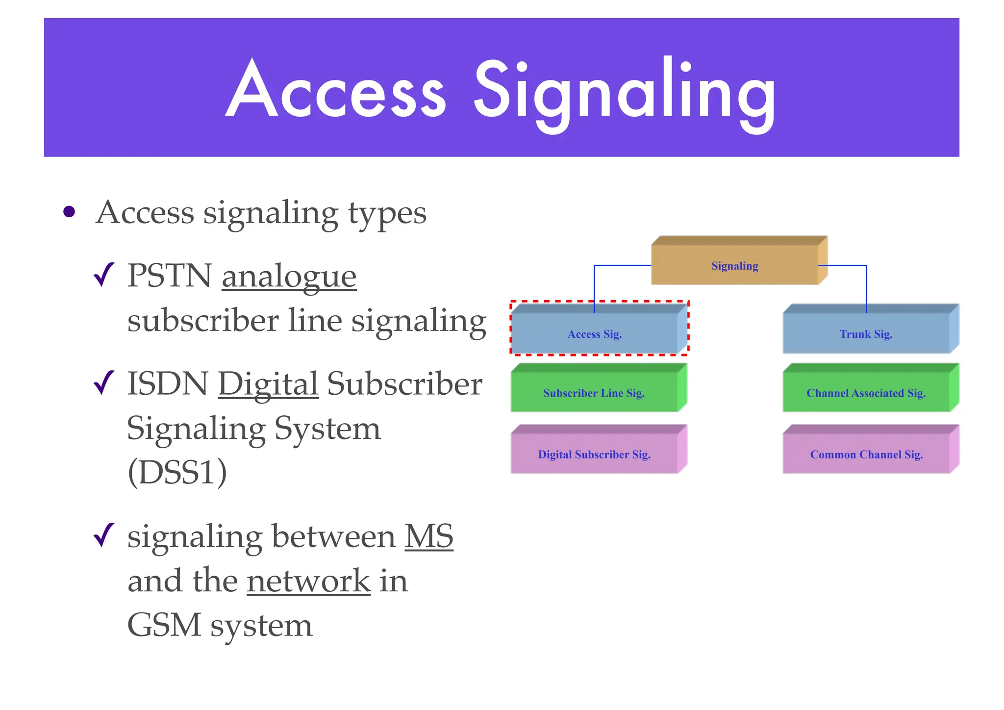
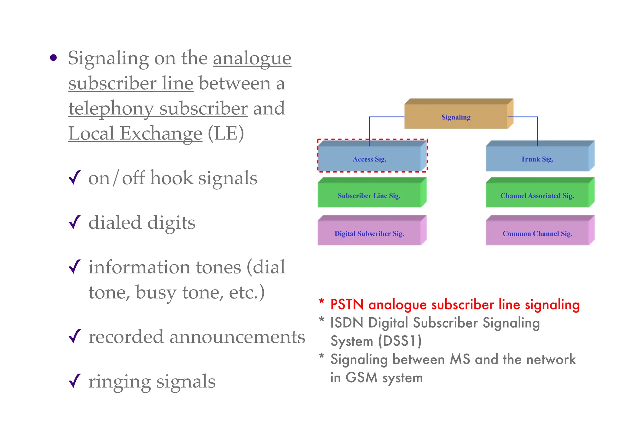
Digital Subscriber Sig.
Subscriber Line Sig.
Access Sig.
Signaling
Trunk Sig.
Channel Associated Sig.
Common Channel Sig.
Pulse-Code Modulation (PCM)
* A method used to digitally represent
sampled analog signals. It is the standard
form of digital audio in computers,
Compact Discs, digital telephony and
other digital audio applications.
* In a PCM stream, the magnitude [強度] of
the analog signal is sampled regularly at
uniform intervals, and each sample is
quantized to the nearest value within a
range of digital steps.](https://image.slidesharecdn.com/globalsystemformobilecommunications1-240318191335-f6ac809a/75/Global-System-for-Mobile-Communications-1-pdf-91-2048.jpg)
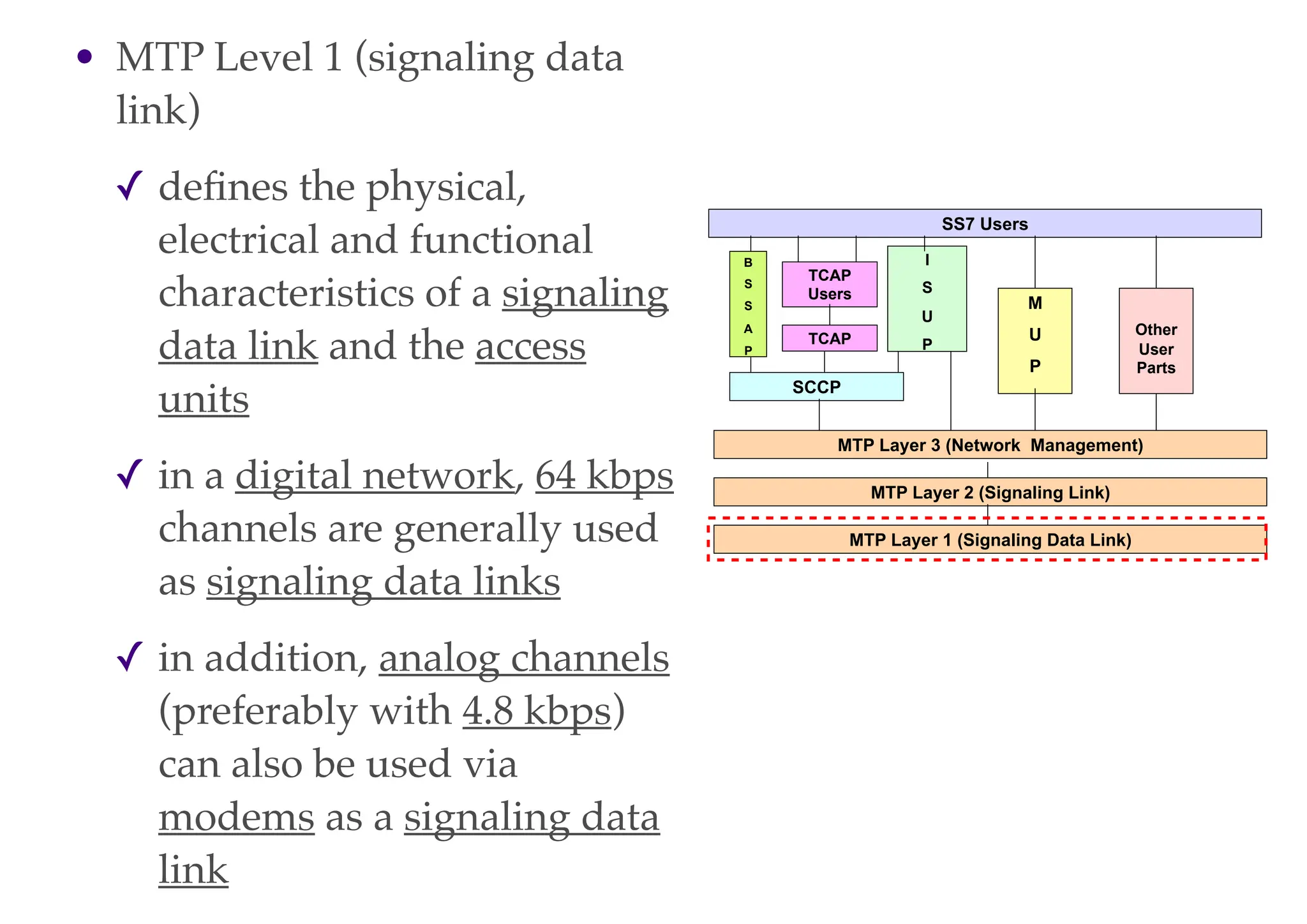
![• MTP Level 2 (signaling link)
✓ defines the functions and procedures
for a correct exchange of user
messages via a signaling link
✓ functions
‣ delimitation of the signal units by
flags
‣ elimination of superfluous [多餘的]
flags
‣ error detection using check bits
‣ error correction by retransmitting
signal units
‣ error rate monitoring on the
signaling data link
‣ restoration of fault-free operation,
e.g., after disruption [破裂] of the
signaling data link
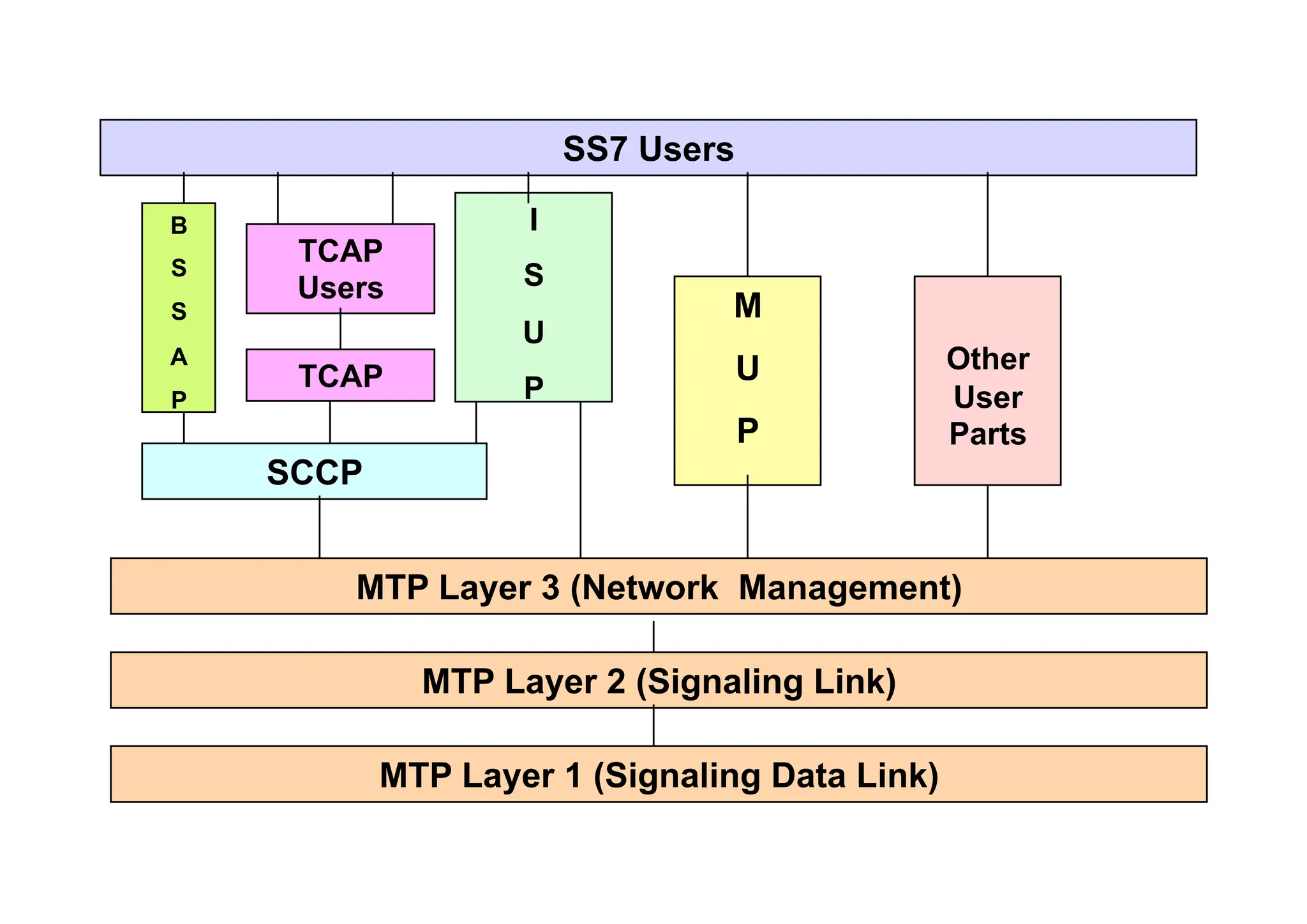
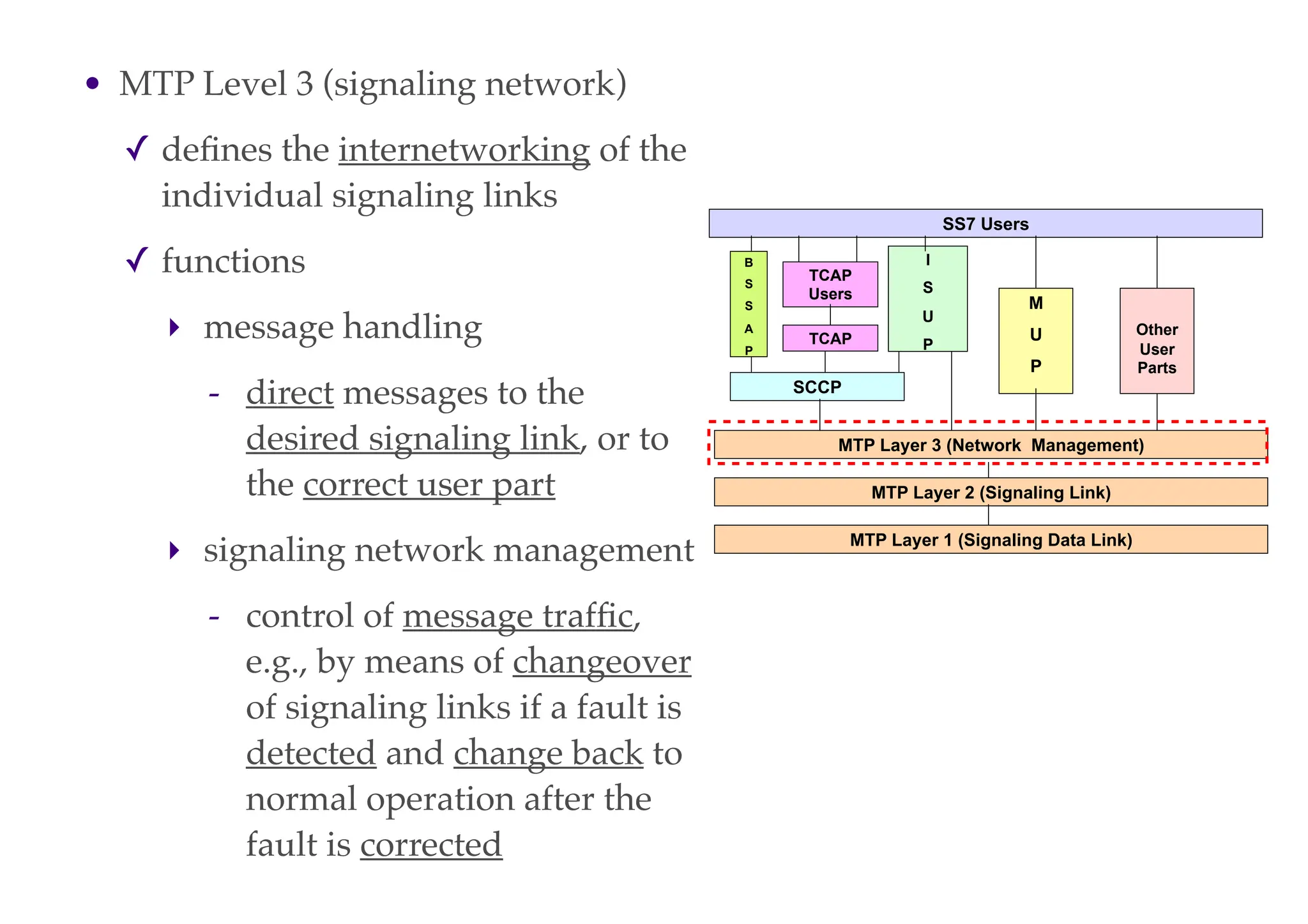
MTP Layer 3 (Network Management)
MTP Layer 1 (Signaling Data Link)
MTP Layer 2 (Signaling Link)
SCCP
B
S
S
A
P
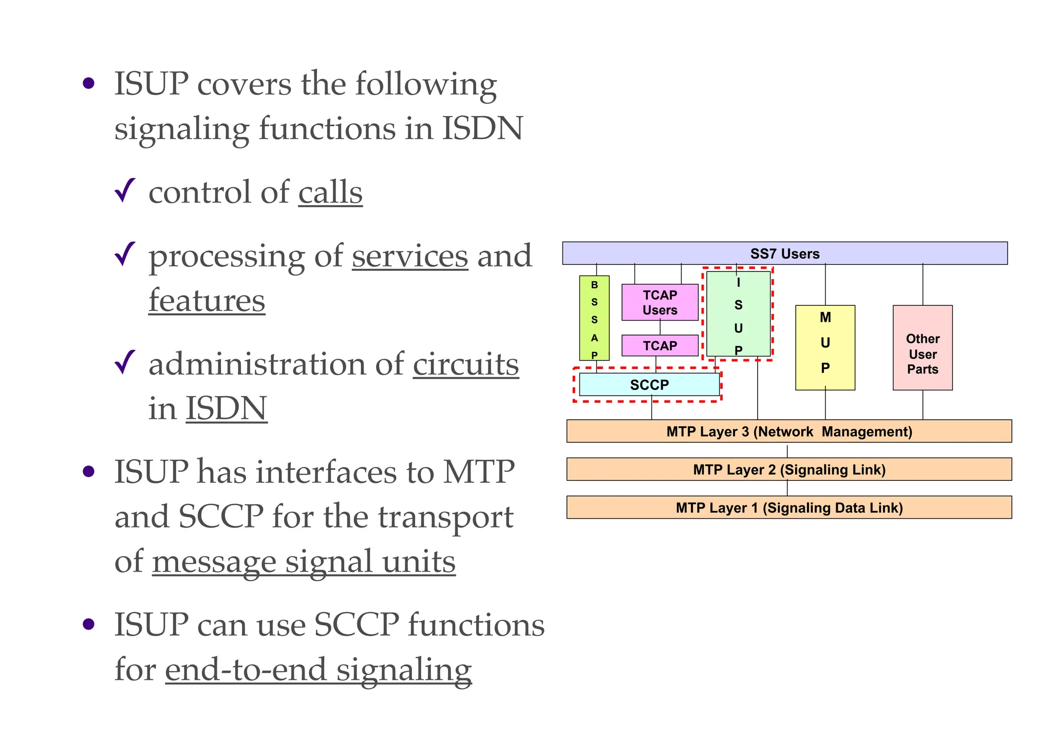
I
S
U
P
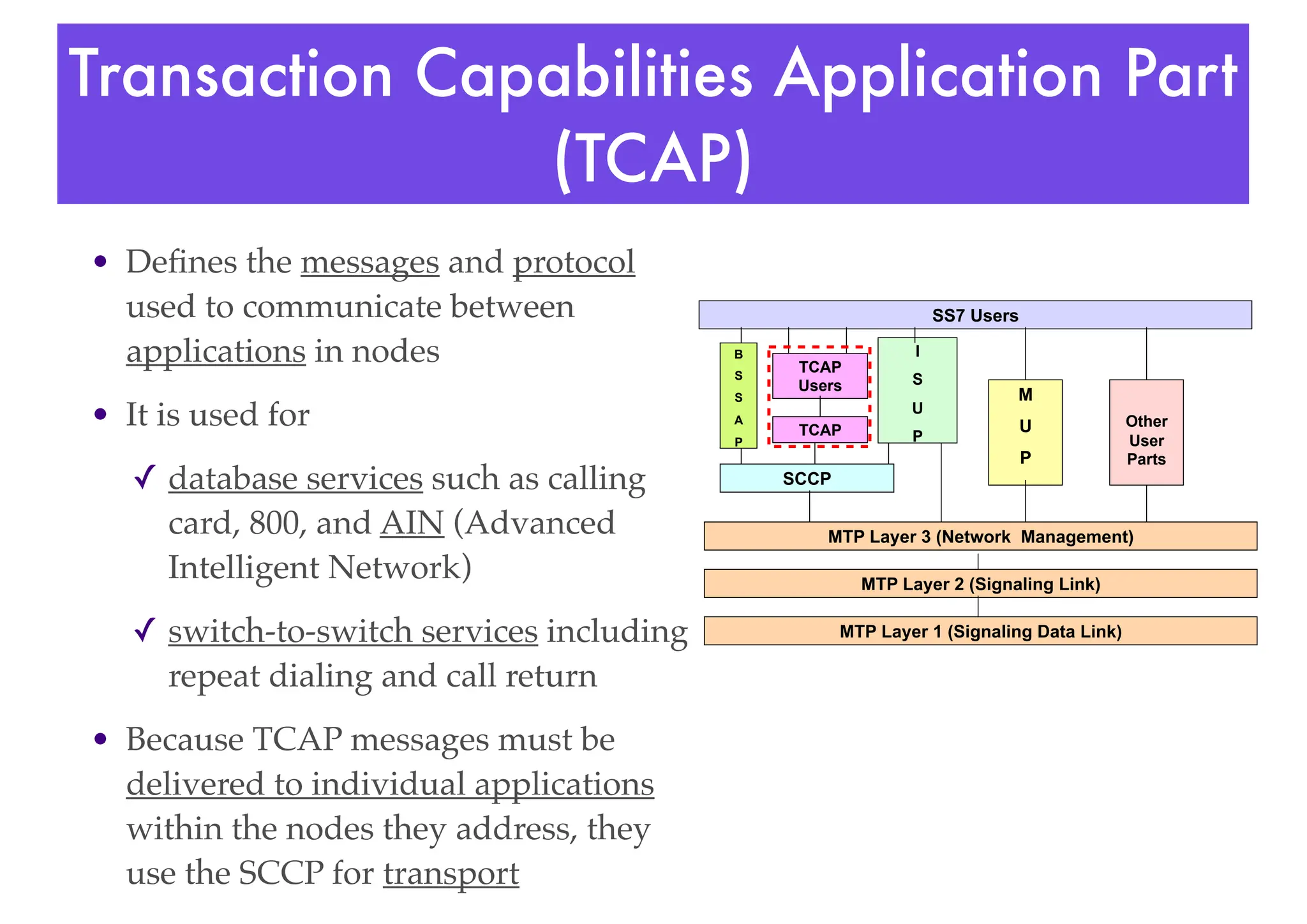
TCAP
TCAP
Users
SS7 Users
M
U
P
Other
User
Parts](https://image.slidesharecdn.com/globalsystemformobilecommunications1-240318191335-f6ac809a/75/Global-System-for-Mobile-Communications-1-pdf-111-2048.jpg)
![• Periodic location update
✓ many times the MS enters non-coverage zone
✓ the MSC will keep on paging the MS thus
wasting precious resources
✓ to avoid this the MS has to inform the MSC about
its current LAI in a set period of time
✓ this time ranges from 0 to 255 decihours
[1 decihour = 6 minutes]
✓ periodic location timer value is broadcast on
BCCH sys info messages](https://image.slidesharecdn.com/globalsystemformobilecommunications1-240318191335-f6ac809a/75/Global-System-for-Mobile-Communications-1-pdf-129-2048.jpg)