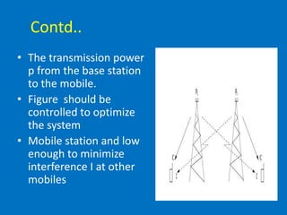
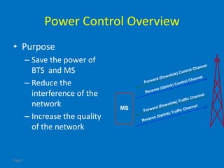
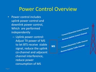
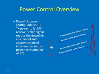
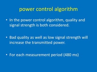
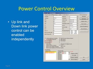
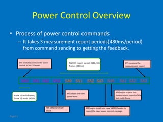
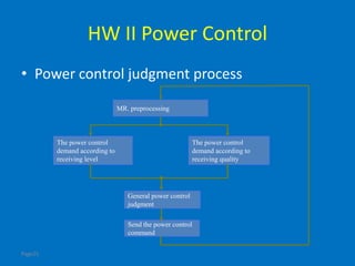
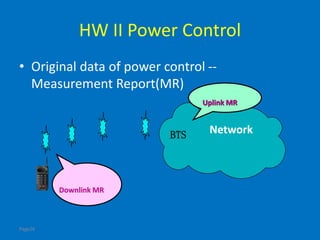
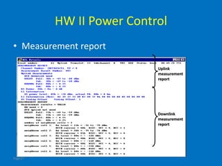
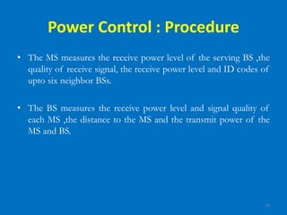
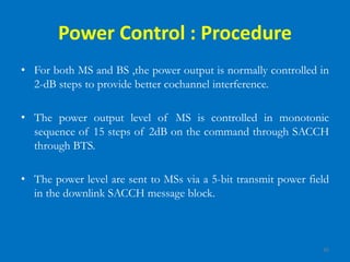
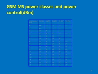
Power Control Strategies
of GSM And CDMA
Presented By.
Prashant Kumar
152613
M.E(ECE)
Submitted To
Dr. S B L Sachan
(Professor)
Power Control in GSM
Introduction
• Power control (PC) refers to the strategies or
techniques required to adjust the transmitted
power
• Power control regulates the transmitted
power to achieve a desired signal strength
Page4
Power Control Overview
–Adjust the transmitting power of BTS and
MS when needed.
–Based on measurement reports of BTS and
MS
• Power control is used both in uplink and in
downlink between base station and mobile
Contd..
• The transmission power
p from the base station
to the mobile.
• Figure should be
controlled to optimize
the system
• Mobile station and low
enough to minimize
interference I at other
mobiles
Page6
Power Control Overview
• Purpose
– Save the power of
BTS and MS
– Reduce the
interference of the
network
– Increase the quality
of the network
MS
Page7
Power Control Overview
• Power control includes
uplink power control and
downlink power control,
Which are performed
independently
– Uplink power control:
Adjust TX power of MS
to let BTS receive stable
signal, reduce the uplink
co-channel and adjacent
channel interference,
reduce power
consumption of MS
MS
Page8
Power Control Overview
– Downlink power
control: Adjust BTS
TX power to let MS
receive stable signal,
reduce the downlink
co-channel and
adjacent channel
interference, reduce
power consumption
of BTS
MS
The carrier to interference ratio(C/I)
• This measurement is the relation between the
carrier signal power C and the interference
power I.
• The carrier signal power, in dB, for one
connection is defined as.
C(t) = p(t) + g(t),
p(t) is the transmitted power in the downlink
g(t) is the gain between the mobile and the base station
Contd..
• The interfering power from neighboring cells
with the same carrier frequencies.
• The C/I, in dB, for each mobile is defined as
C/I = C(t) − I(t) = p(t) + g(t) − I(t).
Where I(t) contains both of the interference carrier power from
other base stations and the thermal noise,
power control algorithm
• In the power control algorithm, quality and
signal strength is both considered.
• Bad quality as well as low signal strength will
increase the transmitted power.
• For each measurement period (480 ms)
Contd..
• There are two variables, rxqual and rxlev, are
reported based on measurement from all
bursts during that measurement period.
• The variables rxqual and rxlev stands for
received quality and received signal strenght
Contd.
• These variables are used to adjust the
transmitted power.
• Predefined values for quality respectively
signal strength defines values for controlling
rxqual and rxlev in the regulation process
Contd.
• The variables, rxqual and rxlev are filtered
with nonlinear exponential filters in order to
eliminate variations of temporal nature.
• The measurement reporting causes a delay
that typically is three periods
Contd..
• The controlling parameter for rxqual in the
regulation is qdes, and for rxlev the parameter
ssdes.
• The qdes value is the target value that
specifies
• The desired quality. Internally, qdes and rxqual
are converted to C/I-valus, expressed in dB
according to Table.
Contd..
• Table : The conversion between qdes, rxqual
and C/I. The unit dtqu stands for deci-
transformed quality units.
Contd.
• The instruction for the change in power for
the regulation is given by.
where α and β is the path loss respective quality compensation
and qdesDBand rxqualDBfiltered are the qdes and rxqual
mapped to C/I as in table
Contd.
• The power level down regulation order is then
given by.
• where INT truncates the power level to a higher value. PL
could have values from 0 to 15, and that represent a down
regulation of 0 to 30 dB
The final output power level by the BTS
• The final output power level by the BTS,
BTS output power = pmax − 2 PL
where pmax correspond to full power
Page20
Power Control Overview
• Up link and
Down link power
control can be
enabled
independently
Page21
Power Control Overview
• Process of power control commands
– It takes 3 measurement report periods(480ms/period)
from command sending to getting the feedback.
SA0 SA1SA0 SA0SA1SA1 SA2SA2SA2 SA3SA3SA3
BTS sends the command for power
control in SACCH header.
MS obtains SACCH
block
MS begins to send the
measurement report of the
last multi-frame.
In the 26 multi-frames,
frame 12 sends SACCH.
BTS receives the
measurement report
SACCCH report period: 26X4=104
frames (480ms)
MS adopts the new
power level
MS begins to set up a new SACCH header to
report the new power control message.
Page22
Data Configuration of Power Control Period
Page23
Power Control Judgment
– Power control judgment is controlled by BTS
measurement report pre-processing item which
can be selected in handover control data table
– MR. Pre-process (measurement report pre-
processing): This switch decide where power
control be processed. If measurement report pre-
processing is “yes”, power control is processed in
BTS, and when setting it “no”, power control is
processed in BSC
Page24
Data Configuration of MR Preprocessing(1)
Page25
HW II Power Control
• Power control judgment process
The power control
demand according to
receiving level
General power control
judgment
Send the power control
command
The power control
demand according to
receiving quality
MR. preprocessing
Page26
HW II Power Control
• Original data of power control --
Measurement Report(MR)
Network
Downlink MR
Uplink MR
BTS
Page27
HW II Power Control
• Measurement report
Uplink
measurement
report
Downlink
measurement
report
28
Power Control to Reduce Interference
 In practical systems, power level of every subscriber
is under constant control by the serving BS.
Power control not only reduces interference levels
but also prolongs battery life.
Reduced Interference leads to high capacity
29
Power Control
• The GSM network is designed so that the MS is instructed to use
only the minimum power level necessary to achieve effective
communication with the BTS.
• GSM requires that every mobile station is subject to power
control. For the BTS, on the other hand, power control is
optional.
• Depending on the quality of a connection, the BSC will request
the BTS and the mobile station to adjust their output power.
Power Control: Need?
• Power control allows
the modification of
MS and BTS transmit
power.
Minimizes interference
Maximizes battery life
Max. MS
Power
(W)/dBm
BS Power
class
Maximum RF
Power (W)/dBm
20/43 I 320/55
8/39 II 160/52
5/37 III 80/49
2/33 IV 40/46
0.8/29 V 20/43
VI 10/40
VII 5/37
VIII 2.5/34
Power Control: Need?
• GSM defines eight
power classes for the
BTS transmitter to
cover five classes of
MS.
Max. MS
Power
(W)/dBm
BS Power
class
Maximum RF
Power (W)/dBm
20/43 I 320/55
8/39 II 160/52
5/37 III 80/49
2/33 IV 40/46
0.8/29 V 20/43
VI 10/40
VII 5/37
VIII 2.5/34
Signal and Quality Level In GSM
• Signal Lavel in
GSM
• Eight Signal
velues
> - 48638
- 49 to - 48627
..6
..5
- 108 to - 10734
- 109 to - 10823
- 110 to - 10912
< -11001
dBmRXLEVS.No
Signal level values in GSM
Signal and Quality Level In GSM
• Quality Level In
GSM
6.4 to 12.867
> 12.878
3.2 to 6..456
1.6 to 3.245
0.8 to 1.634
0.4 to 0.823
0.2 to 0.412
< 0.201
Bit Error Rate
(BER)(%)
RXQUALS.No
Quality level values in GSM
34
Power Control : Procedure
• The MS measures the receive power level of the serving BS ,the
quality of receive signal, the receive power level and ID codes of
upto six neighbor BSs.
• The BS measures the receive power level and signal quality of
each MS ,the distance to the MS and the transmit power of the
MS and BS.
35
Power Control : Procedure
• For both MS and BS ,the power output is normally controlled in
2-dB steps to provide better cochannel interference.
• The power output level of MS is controlled in monotonic
sequence of 15 steps of 2dB on the command through SACCH
through BTS.
• The power level are sent to MSs via a 5-bit transmit power field
in the downlink SACCH message block.
36
GSM MS power classes and power
control(dBm)
151515151514
131313131315
25252525259
232323232310
212121212111
27272727278
191919191912
171717171713
29292929297
----313131316
----333333335
--------3535354
--------3737373
------------39392
----------------411
----------------430
V(0.8W)IV (2W)III (5W)II (8W)I (20W )Power control
level
37
Power Control
• The BSC informs the BTS via the Abis-interface
within a BS_POWER_CON message of the
output power to be used .
• Only if necessary, the BSC will send an
MS_POWER_CON message to the BTS to
initiate an adjustment of the output power of
the mobile station.
Power Control
• This new output power level is forwarded to the
mobile station within the Layer 1 header of the
SACCH to be sent.
• One SACCH is sent to the mobile station every
480 ms, always telling the mobile station the
current output power.
39
Cellular Subscriber Growth Worldwide
• Graph plotted
between the
number of
subscriber
forecast and Year
40
Top 10 Emerging Mobile Markets
• World top 10
mobile
markets data
in 2006
Power Control in CDMA
References
• Vijay K Garg, ”Wireless Communications and
Networking”.
• Theodore S.Rappaport, “ Wireless
Communications”
• F.Gunnarsson, F.Gustafsson, J.Blom.
’Estimation and outer loop power control in
cellular radio systems’. Linköping University,
February, 2001.
THANK YOU

Wmc ppt

  • 1.
    Power Control Strategies ofGSM And CDMA Presented By. Prashant Kumar 152613 M.E(ECE) Submitted To Dr. S B L Sachan (Professor)
  • 2.
  • 3.
    Introduction • Power control(PC) refers to the strategies or techniques required to adjust the transmitted power • Power control regulates the transmitted power to achieve a desired signal strength
  • 4.
    Page4 Power Control Overview –Adjustthe transmitting power of BTS and MS when needed. –Based on measurement reports of BTS and MS • Power control is used both in uplink and in downlink between base station and mobile
  • 5.
    Contd.. • The transmissionpower p from the base station to the mobile. • Figure should be controlled to optimize the system • Mobile station and low enough to minimize interference I at other mobiles
  • 6.
    Page6 Power Control Overview •Purpose – Save the power of BTS and MS – Reduce the interference of the network – Increase the quality of the network MS
  • 7.
    Page7 Power Control Overview •Power control includes uplink power control and downlink power control, Which are performed independently – Uplink power control: Adjust TX power of MS to let BTS receive stable signal, reduce the uplink co-channel and adjacent channel interference, reduce power consumption of MS MS
  • 8.
    Page8 Power Control Overview –Downlink power control: Adjust BTS TX power to let MS receive stable signal, reduce the downlink co-channel and adjacent channel interference, reduce power consumption of BTS MS
  • 9.
    The carrier tointerference ratio(C/I) • This measurement is the relation between the carrier signal power C and the interference power I. • The carrier signal power, in dB, for one connection is defined as. C(t) = p(t) + g(t), p(t) is the transmitted power in the downlink g(t) is the gain between the mobile and the base station
  • 10.
    Contd.. • The interferingpower from neighboring cells with the same carrier frequencies. • The C/I, in dB, for each mobile is defined as C/I = C(t) − I(t) = p(t) + g(t) − I(t). Where I(t) contains both of the interference carrier power from other base stations and the thermal noise,
  • 11.
    power control algorithm •In the power control algorithm, quality and signal strength is both considered. • Bad quality as well as low signal strength will increase the transmitted power. • For each measurement period (480 ms)
  • 12.
    Contd.. • There aretwo variables, rxqual and rxlev, are reported based on measurement from all bursts during that measurement period. • The variables rxqual and rxlev stands for received quality and received signal strenght
  • 13.
    Contd. • These variablesare used to adjust the transmitted power. • Predefined values for quality respectively signal strength defines values for controlling rxqual and rxlev in the regulation process
  • 14.
    Contd. • The variables,rxqual and rxlev are filtered with nonlinear exponential filters in order to eliminate variations of temporal nature. • The measurement reporting causes a delay that typically is three periods
  • 15.
    Contd.. • The controllingparameter for rxqual in the regulation is qdes, and for rxlev the parameter ssdes. • The qdes value is the target value that specifies • The desired quality. Internally, qdes and rxqual are converted to C/I-valus, expressed in dB according to Table.
  • 16.
    Contd.. • Table :The conversion between qdes, rxqual and C/I. The unit dtqu stands for deci- transformed quality units.
  • 17.
    Contd. • The instructionfor the change in power for the regulation is given by. where α and β is the path loss respective quality compensation and qdesDBand rxqualDBfiltered are the qdes and rxqual mapped to C/I as in table
  • 18.
    Contd. • The powerlevel down regulation order is then given by. • where INT truncates the power level to a higher value. PL could have values from 0 to 15, and that represent a down regulation of 0 to 30 dB
  • 19.
    The final outputpower level by the BTS • The final output power level by the BTS, BTS output power = pmax − 2 PL where pmax correspond to full power
  • 20.
    Page20 Power Control Overview •Up link and Down link power control can be enabled independently
  • 21.
    Page21 Power Control Overview •Process of power control commands – It takes 3 measurement report periods(480ms/period) from command sending to getting the feedback. SA0 SA1SA0 SA0SA1SA1 SA2SA2SA2 SA3SA3SA3 BTS sends the command for power control in SACCH header. MS obtains SACCH block MS begins to send the measurement report of the last multi-frame. In the 26 multi-frames, frame 12 sends SACCH. BTS receives the measurement report SACCCH report period: 26X4=104 frames (480ms) MS adopts the new power level MS begins to set up a new SACCH header to report the new power control message.
  • 22.
    Page22 Data Configuration ofPower Control Period
  • 23.
    Page23 Power Control Judgment –Power control judgment is controlled by BTS measurement report pre-processing item which can be selected in handover control data table – MR. Pre-process (measurement report pre- processing): This switch decide where power control be processed. If measurement report pre- processing is “yes”, power control is processed in BTS, and when setting it “no”, power control is processed in BSC
  • 24.
    Page24 Data Configuration ofMR Preprocessing(1)
  • 25.
    Page25 HW II PowerControl • Power control judgment process The power control demand according to receiving level General power control judgment Send the power control command The power control demand according to receiving quality MR. preprocessing
  • 26.
    Page26 HW II PowerControl • Original data of power control -- Measurement Report(MR) Network Downlink MR Uplink MR BTS
  • 27.
    Page27 HW II PowerControl • Measurement report Uplink measurement report Downlink measurement report
  • 28.
    28 Power Control toReduce Interference  In practical systems, power level of every subscriber is under constant control by the serving BS. Power control not only reduces interference levels but also prolongs battery life. Reduced Interference leads to high capacity
  • 29.
    29 Power Control • TheGSM network is designed so that the MS is instructed to use only the minimum power level necessary to achieve effective communication with the BTS. • GSM requires that every mobile station is subject to power control. For the BTS, on the other hand, power control is optional. • Depending on the quality of a connection, the BSC will request the BTS and the mobile station to adjust their output power.
  • 30.
    Power Control: Need? •Power control allows the modification of MS and BTS transmit power. Minimizes interference Maximizes battery life Max. MS Power (W)/dBm BS Power class Maximum RF Power (W)/dBm 20/43 I 320/55 8/39 II 160/52 5/37 III 80/49 2/33 IV 40/46 0.8/29 V 20/43 VI 10/40 VII 5/37 VIII 2.5/34
  • 31.
    Power Control: Need? •GSM defines eight power classes for the BTS transmitter to cover five classes of MS. Max. MS Power (W)/dBm BS Power class Maximum RF Power (W)/dBm 20/43 I 320/55 8/39 II 160/52 5/37 III 80/49 2/33 IV 40/46 0.8/29 V 20/43 VI 10/40 VII 5/37 VIII 2.5/34
  • 32.
    Signal and QualityLevel In GSM • Signal Lavel in GSM • Eight Signal velues > - 48638 - 49 to - 48627 ..6 ..5 - 108 to - 10734 - 109 to - 10823 - 110 to - 10912 < -11001 dBmRXLEVS.No Signal level values in GSM
  • 33.
    Signal and QualityLevel In GSM • Quality Level In GSM 6.4 to 12.867 > 12.878 3.2 to 6..456 1.6 to 3.245 0.8 to 1.634 0.4 to 0.823 0.2 to 0.412 < 0.201 Bit Error Rate (BER)(%) RXQUALS.No Quality level values in GSM
  • 34.
    34 Power Control :Procedure • The MS measures the receive power level of the serving BS ,the quality of receive signal, the receive power level and ID codes of upto six neighbor BSs. • The BS measures the receive power level and signal quality of each MS ,the distance to the MS and the transmit power of the MS and BS.
  • 35.
    35 Power Control :Procedure • For both MS and BS ,the power output is normally controlled in 2-dB steps to provide better cochannel interference. • The power output level of MS is controlled in monotonic sequence of 15 steps of 2dB on the command through SACCH through BTS. • The power level are sent to MSs via a 5-bit transmit power field in the downlink SACCH message block.
  • 36.
    36 GSM MS powerclasses and power control(dBm) 151515151514 131313131315 25252525259 232323232310 212121212111 27272727278 191919191912 171717171713 29292929297 ----313131316 ----333333335 --------3535354 --------3737373 ------------39392 ----------------411 ----------------430 V(0.8W)IV (2W)III (5W)II (8W)I (20W )Power control level
  • 37.
    37 Power Control • TheBSC informs the BTS via the Abis-interface within a BS_POWER_CON message of the output power to be used . • Only if necessary, the BSC will send an MS_POWER_CON message to the BTS to initiate an adjustment of the output power of the mobile station.
  • 38.
    Power Control • Thisnew output power level is forwarded to the mobile station within the Layer 1 header of the SACCH to be sent. • One SACCH is sent to the mobile station every 480 ms, always telling the mobile station the current output power.
  • 39.
    39 Cellular Subscriber GrowthWorldwide • Graph plotted between the number of subscriber forecast and Year
  • 40.
    40 Top 10 EmergingMobile Markets • World top 10 mobile markets data in 2006
  • 41.
  • 42.
    References • Vijay KGarg, ”Wireless Communications and Networking”. • Theodore S.Rappaport, “ Wireless Communications” • F.Gunnarsson, F.Gustafsson, J.Blom. ’Estimation and outer loop power control in cellular radio systems’. Linköping University, February, 2001.
  • 43.