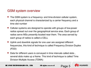
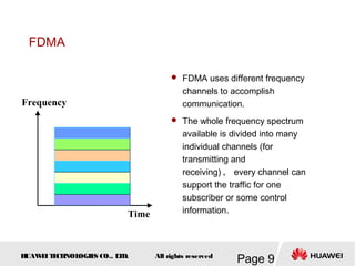
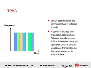
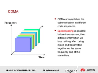
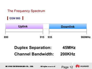
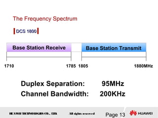
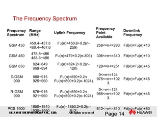
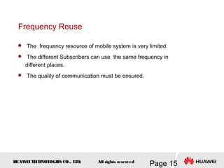
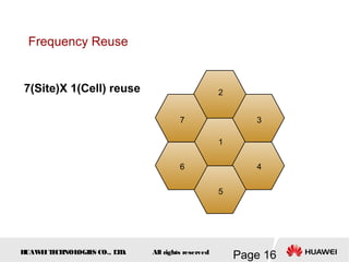
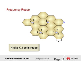
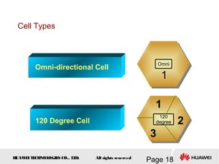
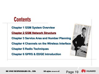
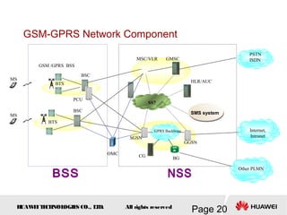
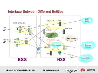
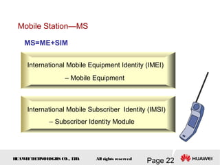
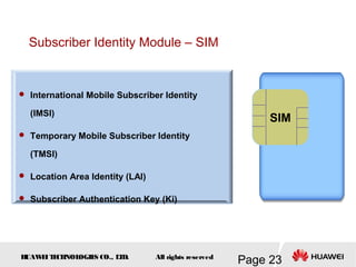
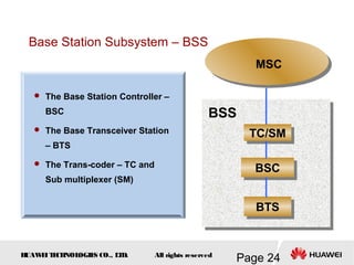
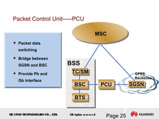
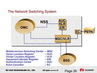
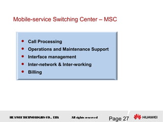
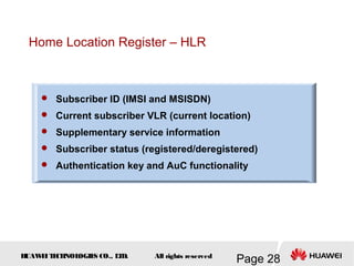
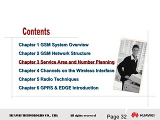
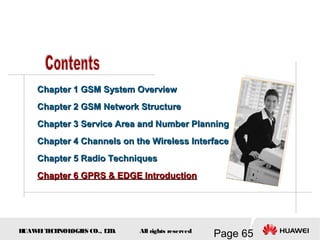
This document provides an overview of the fundamentals of GSM systems. It begins with learning objectives and outlines 6 chapters that will cover topics like GSM network structure, service area and number planning, channels on the wireless interface, radio techniques, and GPRS and EDGE introduction. The document then goes into details on concepts like GSM system overview describing frequency-division duplex and time-division multiple access techniques, frequency reuse, cell types, and multiple access techniques used in GSM. Network components of GSM like the mobile station, base station subsystem, and network switching system are also summarized.
Radioenlaces por microondas.
Caracteristicas, ventajas e inconvenientes, etructura general de un rarioenlace, canalizacion, planificacion de radioenlaces, traado de perfiles, equipos de radioenlaces, lineas de transmision y antenas, potencia, ruido, interferencia, desvanecimiento, técnicas de diversidad,
CFD Simulation of By-pass Flow in a HRSG module by R&R Consult.pptxR&R Consult
CFD analysis is incredibly effective at solving mysteries and improving the performance of complex systems!
Here's a great example: At a large natural gas-fired power plant, where they use waste heat to generate steam and energy, they were puzzled that their boiler wasn't producing as much steam as expected.
R&R and Tetra Engineering Group Inc. were asked to solve the issue with reduced steam production.
An inspection had shown that a significant amount of hot flue gas was bypassing the boiler tubes, where the heat was supposed to be transferred.
R&R Consult conducted a CFD analysis, which revealed that 6.3% of the flue gas was bypassing the boiler tubes without transferring heat. The analysis also showed that the flue gas was instead being directed along the sides of the boiler and between the modules that were supposed to capture the heat. This was the cause of the reduced performance.
Based on our results, Tetra Engineering installed covering plates to reduce the bypass flow. This improved the boiler's performance and increased electricity production.
It is always satisfying when we can help solve complex challenges like this. Do your systems also need a check-up or optimization? Give us a call!
Work done in cooperation with James Malloy and David Moelling from Tetra Engineering.
More examples of our work https://www.r-r-consult.dk/en/cases-en/
Industrial Training at Shahjalal Fertilizer Company Limited (SFCL)MdTanvirMahtab2
This presentation is about the working procedure of Shahjalal Fertilizer Company Limited (SFCL). A Govt. owned Company of Bangladesh Chemical Industries Corporation under Ministry of Industries.
Saudi Arabia stands as a titan in the global energy landscape, renowned for its abundant oil and gas resources. It's the largest exporter of petroleum and holds some of the world's most significant reserves. Let's delve into the top 10 oil and gas projects shaping Saudi Arabia's energy future in 2024.
Immunizing Image Classifiers Against Localized Adversary Attacksgerogepatton
This paper addresses the vulnerability of deep learning models, particularly convolutional neural networks
(CNN)s, to adversarial attacks and presents a proactive training technique designed to counter them. We
introduce a novel volumization algorithm, which transforms 2D images into 3D volumetric representations.
When combined with 3D convolution and deep curriculum learning optimization (CLO), itsignificantly improves
the immunity of models against localized universal attacks by up to 40%. We evaluate our proposed approach
using contemporary CNN architectures and the modified Canadian Institute for Advanced Research (CIFAR-10
and CIFAR-100) and ImageNet Large Scale Visual Recognition Challenge (ILSVRC12) datasets, showcasing
accuracy improvements over previous techniques. The results indicate that the combination of the volumetric
input and curriculum learning holds significant promise for mitigating adversarial attacks without necessitating
adversary training.
Hybrid optimization of pumped hydro system and solar- Engr. Abdul-Azeez.pdffxintegritypublishin
Advancements in technology unveil a myriad of electrical and electronic breakthroughs geared towards efficiently harnessing limited resources to meet human energy demands. The optimization of hybrid solar PV panels and pumped hydro energy supply systems plays a pivotal role in utilizing natural resources effectively. This initiative not only benefits humanity but also fosters environmental sustainability. The study investigated the design optimization of these hybrid systems, focusing on understanding solar radiation patterns, identifying geographical influences on solar radiation, formulating a mathematical model for system optimization, and determining the optimal configuration of PV panels and pumped hydro storage. Through a comparative analysis approach and eight weeks of data collection, the study addressed key research questions related to solar radiation patterns and optimal system design. The findings highlighted regions with heightened solar radiation levels, showcasing substantial potential for power generation and emphasizing the system's efficiency. Optimizing system design significantly boosted power generation, promoted renewable energy utilization, and enhanced energy storage capacity. The study underscored the benefits of optimizing hybrid solar PV panels and pumped hydro energy supply systems for sustainable energy usage. Optimizing the design of solar PV panels and pumped hydro energy supply systems as examined across diverse climatic conditions in a developing country, not only enhances power generation but also improves the integration of renewable energy sources and boosts energy storage capacities, particularly beneficial for less economically prosperous regions. Additionally, the study provides valuable insights for advancing energy research in economically viable areas. Recommendations included conducting site-specific assessments, utilizing advanced modeling tools, implementing regular maintenance protocols, and enhancing communication among system components.
Overview of the fundamental roles in Hydropower generation and the components involved in wider Electrical Engineering.
This paper presents the design and construction of hydroelectric dams from the hydrologist’s survey of the valley before construction, all aspects and involved disciplines, fluid dynamics, structural engineering, generation and mains frequency regulation to the very transmission of power through the network in the United Kingdom.
Author: Robbie Edward Sayers
Collaborators and co editors: Charlie Sims and Connor Healey.
(C) 2024 Robbie E. Sayers
2. H
UAW
E
IT
E
CH
NOL
OGIE
S CO., L
T
D.
Page 2
All rights reserved
Upon completion of this course, you will be able to:
Grasp basic idea of GSM system such as
frequency spectrum, frequency reuse etc.
Grasp the structure of the GSM system and the
protocol used.
Grasp certain numbers that refer to BSS
Grasp the 4 kinds of channel combination and
understand the idea of multi-frame.
Know some radio techniques
Get the idea of EDGE
4. H
UAW
E
IT
E
CH
NOL
OGIE
S CO., L
T
D.
Page 4
All rights reserved
Chapter 1 GSM System Overview
Chapter 2 GSM Network Structure
Chapter 3
Chapter 3 Service Area and Number Planning
Service Area and Number Planning
Chapter 4
Chapter 4 Channels on the Wireless Interface
Channels on the Wireless Interface
Chapter 5 Radio Techniques
Chapter 6 GPRS & EDGE Introduction
5. H
UAW
E
IT
E
CH
NOL
OGIE
S CO., L
T
D.
Page 5
All rights reserved
GSM system overview
The GSM system is a frequency- and time-division cellular system,
each physical channel is characterized by a carrier frequency and a
time slot number
Cellular systems are designed to operate with groups of low-power
radios spread out over the geographical service area. Each group of
radios serve MSs presently located near them. The area served by
each group of radios is called a CELL
Uplink and downlink signals for one user are assigned different
frequencies, this kind of technique is called Frequency Division Duplex
(FDD)
Data for different users is conveyed in time intervals called slots ,
several slots make up a frame. This kind of technique is called Time
Division Multiple Access (TDMA)
6. H
UAW
E
IT
E
CH
NOL
OGIE
S CO., L
T
D.
Page 6
All rights reserved
GSM Development
Standard Protocol for GSM take effect
System was named as Global System for
Mobile Communication
GSM system began to provide service in Europe(2G)
Provide services for the whole world
Micro Cell Technique is used in GSM system
1989
1991
1992
1994
1996
7. H
UAW
E
IT
E
CH
NOL
OGIE
S CO., L
T
D.
Page 7
All rights reserved
Cell Technique
A certain radio coverage area formed by a set of transceivers that
connected to a set of antennas is called a CELL.
Macro Cell
In the beginning , High-Power BTSs are adopted to provide services.
The BTS covers a wider area , but its frequency utilization is not
efficient. So , it can only provide a few channels for subscribers.
Micro Cell
Later the Low-Power BTS joins the system for getting a better service
area with high capacity . At the same time it adopts the frequency reuse
technique to improve the efficiency of the frequency utilization and also
the whole capacity of the network.
Macro Cell and Micro Cell
8. H
UAW
E
IT
E
CH
NOL
OGIE
S CO., L
T
D.
Page 8
All rights reserved
Multiple Access Technique
Multiple Access Technique allows many subscribers to use the
same communication medium.
There are three kinds of basic Multiple Access Technique :
FDMA , TDMA and CDMA.
GSM system adopt FDD-TDMA (FDMA and TDMA together).
9. H
UAW
E
IT
E
CH
NOL
OGIE
S CO., L
T
D.
Page 9
All rights reserved
FDMA
FDMA uses different frequency
channels to accomplish
communication.
The whole frequency spectrum
available is divided into many
individual channels (for
transmitting and
receiving) , every channel can
support the traffic for one
subscriber or some control
information.
Frequency
Time
10. H
UAW
E
IT
E
CH
NOL
OGIE
S CO., L
T
D.
Page 10
All rights reserved
TDMA
TDMA accomplishes the
communication in different
timeslot.
A carrier is divided into
channels based on time.
Different signals occupy
different timeslots in certain
sequence , that is , many
signals are transmitted on
the same frequency in
different time.
Time
Frequency
11. H
UAW
E
IT
E
CH
NOL
OGIE
S CO., L
T
D.
Page 11
All rights reserved
CDMA
CDMA accomplishes the
communication in different
code sequences.
Special coding is adopted
before transmission, then
different information will
lose nothing after being
mixed and transmitted
together on the same
frequency and at the
same time.
Time
Frequency
12. H
UAW
E
IT
E
CH
NOL
OGIE
S CO., L
T
D.
Page 12
All rights reserved
GSM 900
GSM 900
Duplex Separation: 45MHz
Channel Bandwidth: 200KHz
The Frequency Spectrum
Uplink
890 915 935 960MHz
Downlink
13. H
UAW
E
IT
E
CH
NOL
OGIE
S CO., L
T
D.
Page 13
All rights reserved
Duplex Separation: 95MHz
Channel Bandwidth: 200KHz
Base Station Receive
1710 1785 1805 1880MHz
Base Station Transmit
DCS 1800
DCS 1800
The Frequency Spectrum
14. H
UAW
E
IT
E
CH
NOL
OGIE
S CO., L
T
D.
Page 14
All rights reserved
The Frequency Spectrum
Frequency
Spectrum
Range
(MHz)
Uplink Frequency
Frequency
Point
Available
Downlink
Frequency
GSM 450
450.4~457.6
460.4~467.6
Fu(n)=450.6+0.2(n-
259)
259<=n<=293 Fd(n)=Fu(n)+10
GSM 480
478.8~486
488.8~496
Fu(n)=479+0.2(n-306) 306<=n<=340 Fd(n)=Fu(n)+10
GSM 850
824~849
869~894
Fu(n)=824.2+0.2(n-
128)
128<=n<=251 Fd(n)=Fu(n)+45
E-GSM
900
880~915
925~960
Fu(n)=890+0.2n
Fu(n)=890+0.2(n-1024)
0<=n<=124
975<=n<=102
3
Fd(n)=Fu(n)+45
R-GSM
900
876~915
921~960
Fu(n)=890+0.2n
Fu(n)=890+0.2(n-1024)
0<=n<=124
955<=n<=102
3
Fd(n)=Fu(n)+45
PCS 1900
1850~1910
1930~1990
Fu(n)=1850.2+0.2(n-
512)
512<=n<=810 Fd(n)=Fu(n)+80
15. H
UAW
E
IT
E
CH
NOL
OGIE
S CO., L
T
D.
Page 15
All rights reserved
Frequency Reuse
The frequency resource of mobile system is very limited.
The different Subscribers can use the same frequency in
different places.
The quality of communication must be ensured.
19. H
UAW
E
IT
E
CH
NOL
OGIE
S CO., L
T
D.
Page 19
All rights reserved
Chapter 1 GSM System Overview
Chapter 2 GSM Network Structure
Chapter 3
Chapter 3 Service Area and Number Planning
Service Area and Number Planning
Chapter 4
Chapter 4 Channels on the Wireless Interface
Channels on the Wireless Interface
Chapter 5 Radio Techniques
Chapter 6 GPRS & EDGE Introduction
20. H
UAW
E
IT
E
CH
NOL
OGIE
S CO., L
T
D.
Page 20
All rights reserved
GSM-GPRS Network Component
GSM /GPRS BSS
BTS
BSC
BTS
BSC
PCU
SS7
SMS system
PSTN
ISDN
Internet,
Intranet
MSC/VLR GMSC
HLR/AUC
SGSN
CG BG
GGSN
GPRS Backbone
Other PLMN
MS
MS
OMC
21. H
UAW
E
IT
E
CH
NOL
OGIE
S CO., L
T
D.
Page 21
All rights reserved
Interface Between Different Entities
GSM /GPRS BSS
BTS
BSC
BTS
BSC
PCU
SS7
SMS system
PSTN
ISDN
Internet,
Intranet
MSC/VLR GMSC
HLR/AUC
SGSN
CG BG
GGSN
GPRS backbone
Other PLMN
A
Gb
Gi
Gp
C/D/Gs
Gr/Gs/Gd/Ge Gc
Ga
Abis
Um
MS
MS
OMC
22. H
UAW
E
IT
E
CH
NOL
OGIE
S CO., L
T
D.
Page 22
All rights reserved
Mobile Station—MS
International Mobile Equipment Identity (IMEI)
– Mobile Equipment
MS=ME+SIM
International Mobile Subscriber Identity (IMSI)
– Subscriber Identity Module
23. H
UAW
E
IT
E
CH
NOL
OGIE
S CO., L
T
D.
Page 23
All rights reserved
Subscriber Identity Module – SIM
International Mobile Subscriber Identity
(IMSI)
Temporary Mobile Subscriber Identity
(TMSI)
Location Area Identity (LAI)
Subscriber Authentication Key (Ki)
SIM
24. H
UAW
E
IT
E
CH
NOL
OGIE
S CO., L
T
D.
Page 24
All rights reserved
BTS
BTS
BSC
BSC
TC/SM
TC/SM
BSS
MSC
Base Station Subsystem – BSS
The Base Station Controller –
BSC
The Base Transceiver Station
– BTS
The Trans-coder – TC and
Sub multiplexer (SM)
25. H
UAW
E
IT
E
CH
NOL
OGIE
S CO., L
T
D.
Page 25
All rights reserved
BTS
BTS
BSC
BSC
TC/SM
TC/SM
BSS
MSC
Packet Control Unit-----PCU
Packet data
switching
Bridge between
SGSN and BSC
Provide Pb and
Gb interface
GPRS
Backbone
PCU
PCU SGSN
SGSN
26. H
UAW
E
IT
E
CH
NOL
OGIE
S CO., L
T
D.
Page 26
All rights reserved
Mobile-service Switching Center – MSC
Home Location Register – HLR
Visitor Location Register – VLR
Equipment Identity Register – EIR
Authentication Center – AUC
Echo Cancellor – EC
AUC
AUC
HLR
HLR
MSC/VLR
MSC/VLR
PSTN
NSS
EIR
EIR
OMC
BSS
EC
EC
The Network Switching System
27. H
UAW
E
IT
E
CH
NOL
OGIE
S CO., L
T
D.
Page 27
All rights reserved
Mobile-service Switching Center – MSC
Call Processing
Operations and Maintenance Support
Interface management
Inter-network & Inter-working
Billing
28. H
UAW
E
IT
E
CH
NOL
OGIE
S CO., L
T
D.
Page 28
All rights reserved
Home Location Register – HLR
Subscriber ID (IMSI and MSISDN)
Current subscriber VLR (current location)
Supplementary service information
Subscriber status (registered/deregistered)
Authentication key and AuC functionality
29. H
UAW
E
IT
E
CH
NOL
OGIE
S CO., L
T
D.
Page 29
All rights reserved
Visitor Location Register – VLR
Mobile Status (IMSI attached / detached / busy / idle etc.)
Location Area Identity(LAI)
Temporary Mobile Subscriber Identity(TMSI)
Allocating the Roaming Number
30. H
UAW
E
IT
E
CH
NOL
OGIE
S CO., L
T
D.
Page 30
All rights reserved
IMEI is Checked In White List
IMEI is Checked in Black/Grey List
If NOT found
EIR focus on the
equipment , not the
subscriber!!
Equipment Identity Register – EIR
White List
Black List
Grey List
31. H
UAW
E
IT
E
CH
NOL
OGIE
S CO., L
T
D.
Page 31
All rights reserved
OMC Functional Architecture
OS
MMI
DB
Event/Alarm
Management
Security
Management
Configuration
Management
Performance
Management
Fault
Management
32. H
UAW
E
IT
E
CH
NOL
OGIE
S CO., L
T
D.
Page 32
All rights reserved
Chapter 1 GSM System Overview
Chapter 2 GSM Network Structure
Chapter 3
Chapter 3 Service Area and Number Planning
Service Area and Number Planning
Chapter 4
Chapter 4 Channels on the Wireless Interface
Channels on the Wireless Interface
Chapter 5 Radio Techniques
Chapter 6 GPRS & EDGE Introduction
33. H
UAW
E
IT
E
CH
NOL
OGIE
S CO., L
T
D.
Page 33
All rights reserved
Service Area
PLMN service area
......
Service Area
MSC service area...
Location area...
cell
PLMN service area PLMN service area
MSC service area...
Location area...
cell
34. H
UAW
E
IT
E
CH
NOL
OGIE
S CO., L
T
D.
Page 34
All rights reserved
LAI
Location Area Identification
The LAI is the international code for a location area.
MCC: Mobile Country Code , It consists of 3 digits .
For example: The MCC of China is "460"
MNC: Mobile Network Code , It consists of 2 digits .
For example: The MNC of China Mobile is "00"
LAC: Location Area Code , It is a two bytes hex code.
The value 0000 and FFFF is invalid.
For example: 460-00-0011
MCC MNC LAC
35. H
UAW
E
IT
E
CH
NOL
OGIE
S CO., L
T
D.
Page 35
All rights reserved
CGI
The CGI is a unique international identification for a cell
The format is LAI+CI
LAI: Location Area Identification
CI: Cell Identity. This code uses two bytes hex code to
identify the cells within an LAI.
For example : 460-00-0011-0001
CGI: Cell Global Identification
36. H
UAW
E
IT
E
CH
NOL
OGIE
S CO., L
T
D.
Page 36
All rights reserved
BSIC
NCC: PLMN network color code. It comprises 3 bit. It
allows various neighboring PLMNs to be
distinguished.
BCC: BTS color code. It comprises 3 bit, used to
distinguish different cells assigned the same
frequency!
NCC BCC
BSIC
BSIC ( Base Station Identification Color Code)
37. H
UAW
E
IT
E
CH
NOL
OGIE
S CO., L
T
D.
Page 37
All rights reserved
CC: Country Code. For example: The CC of China is "86".
NDC: National Destination Code. For example: The NDC of
China Telecom is 139, 138, 137, 136, 135.
SN: Subscriber Number. Format:H0 H1 H2 H3 ABCD
Example: 86-139-0666-1234
MSISDN
CC NDC SN
National (significant)
Mobile number
Mobile station international
ISDN number
38. H
UAW
E
IT
E
CH
NOL
OGIE
S CO., L
T
D.
Page 38
All rights reserved
MCC: Mobile Country Code , It consists of 3 digits .
For example: The MCC of China is "460" 。
MNC: Mobile Network Code , It consists of 2 digits .
For example: The MNC of China Telecom is "00" 。
MSIN: Mobile Subscriber Identification Number. H1H2H3 S ABCDEF
For example: 666-9777001
NMSI: National Mobile Subscriber Identification , MNC and MSIN
form it together.
For Example of IMSI : 460-00-666-9777001
Not more than 15 digits
3 digits 2 digits
IMSI
MCC MNC MSIN
NMSI
IMSI
39. H
UAW
E
IT
E
CH
NOL
OGIE
S CO., L
T
D.
Page 39
All rights reserved
TMSI
The TMSI is assigned only after successful subscriber
authentication.
The VLR controls the allocation of new TMSI numbers and notifies
them to the HLR.
TMSI is used to ensure that the identity of the mobile subscriber
on the air interface is kept secret.
The TMSI consists of 4 bytes( 8 HEX numbers) and determined by
the operator.
TMSI: Temporary Mobile Subscriber Identification)
40. H
UAW
E
IT
E
CH
NOL
OGIE
S CO., L
T
D.
Page 40
All rights reserved
IMEI
TAC FAC SNR SP
IMEI
IMEI: International Mobile Station Equipment Identification
TAC: Type approval code, 6 bit, determined by the type approval center
FAC: Final assembly code, 2 bit, It is determined by the manufacturer.
SNR: Serial number, 6 bits, It is issued by the manufacturer of the MS.
SP: 1 bit , Not used.
Check the IMEI in your MS : *#06#
TAC: Type approval code, 6 bit, determined by the type approval center
FAC: Final assembly code, 2 bit, It is determined by the manufacturer.
SNR: Serial number, 6 bits, It is issued by the manufacturer of the MS.
SP: 1 bit , Not used.
Check the IMEI in your MS : *#06#
41. H
UAW
E
IT
E
CH
NOL
OGIE
S CO., L
T
D.
Page 41
All rights reserved
Chapter 1 GSM System Overview
Chapter 2 GSM Network Structure
Chapter 3
Chapter 3 Service Area and Number Planning
Service Area and Number Planning
Chapter 4
Chapter 4 Channels on the Wireless Interface
Channels on the Wireless Interface
Chapter 5 Radio Techniques
Chapter 6 GPRS & EDGE Introduction
42. H
UAW
E
IT
E
CH
NOL
OGIE
S CO., L
T
D.
Page 42
All rights reserved
2 3
0 1
6 7
4 5
2 3
The physical channel is the medium over which the
information is carried: 200KHz and 0.577ms
0 1
TDMA FRAME
Timeslot
The information carried in one time
slot is called a “burst”
The information carried in one time
slot is called a “burst”
Physical Channel and Logical Channel
The logical channel consists of the information carried
over the physical channels
TDMA FRAME
43. H
UAW
E
IT
E
CH
NOL
OGIE
S CO., L
T
D.
Page 43
All rights reserved
Two types of Logical Channel
Traffic Channel (TCH) :
Transmits traffic information, include data
and speech.
Control Channel (CCH) :
Or Signaling Channel, transmits all kinds of
control information.
44. H
UAW
E
IT
E
CH
NOL
OGIE
S CO., L
T
D.
Page 44
All rights reserved
Traffic Channel (TCH)
TCH
Traffic Channels
Speech
TCH/FS
Data
TCH/HS
TCH/9.6 TCH/2.4
TCH/4.8
TCH Traffic Channel
TCH/FS Full rate Speech Channel
TCH/HS Half rate Speech Channel
TCH/9.6 Data Channel 9.6kb/s
TCH/4.8 Data Channel 4.8kb/s
TCH/2.4 Data Channel 2.4Kb/s
45. H
UAW
E
IT
E
CH
NOL
OGIE
S CO., L
T
D.
Page 45
All rights reserved
FCCH
SCH
CCH (Control Channels)
DCCH
SDCCH
BCH
BCCH Synch. CH.
ACCH
SACCH
FACCH CCCH
RACH CBCH
PCH/AGCH
Broadcast Control Channel – BCCH
Common Control Channel – CCCH
Dedicated Control Channel – DCCH
Associated Control Channel – ACCH
Control Channel (CCH)
46. H
UAW
E
IT
E
CH
NOL
OGIE
S CO., L
T
D.
Page 46
All rights reserved
CCH
BCH
BCCH
Synch.
Channels
SCH FCCH
The information carried on the BCCH
is monitored by the MS
periodically when it is in idle mode
BCCH: Broadcast Control Channel
FCCH: Frequency Correction Channel
SCH: Synchronization Channel
Broadcast Control Channel – BCCH
47. H
UAW
E
IT
E
CH
NOL
OGIE
S CO., L
T
D.
Page 47
All rights reserved
CCH
CCCH
RACH
uplink
CBCH
downlink
PCH/AGCH
downlink
The CCCH is responsible for
transferring control information
between all mobiles and the
network.
RACH: Random Access Channel
PCH: Paging Channel
AGCH: Access Granted Channel
CBCH: Cell Broadcast Channel
Common Control Channel – CCCH
48. H
UAW
E
IT
E
CH
NOL
OGIE
S CO., L
T
D.
Page 48
All rights reserved
CCH
DCCH
SDCCH
FACCH SACCH
DCCH is assigned to a single
wireless connection for
measurement and handover
purpose.
SDCCH: Stand-alone Dedicated
Control Channel
ACCH: Associated Control Channel
SACCH: Slow Associated
Control Channel
FACCH: Fast Associated Control
Channel
ACCH
Dedicated Control Channel – DCCH
51. H
UAW
E
IT
E
CH
NOL
OGIE
S CO., L
T
D.
Page 51
All rights reserved
Allocate signaling channel
FCCH
SCH
BCCH
PCH
RACH
AGCH
SDCCH
SDCCH
TCH
FACCH
Power-off
Idle mode
Dedicated mode
Idle mode
How to use these channels?
Search for frequency correction burst
Search for synchronous burst
Extract system information
Monitor paging message
Send access burst
Set up the call
Allocate voice channel
Conversation
Release the call
52. H
UAW
E
IT
E
CH
NOL
OGIE
S CO., L
T
D.
Page 52
All rights reserved
Packet data channel (PDCH)
Comprising packet service channel and packet control channel
Packet service channel (PDTCH)
Combined into the single-directional service channel
Packet control channel
Broadcast control channel: PBCCH
Public control channel: PPCH, PRACH, PAGCH
Private control channel: PACCH, PTCCH
TCH
BCCH
SACCH
Packet logic channel
CCCH
TCH
53. H
UAW
E
IT
E
CH
NOL
OGIE
S CO., L
T
D.
Page 53
All rights reserved
GSM Logical Channel Combination
Main BCCH combination – FCCH + SCH + BCCH + CCCH
SDCCH combination – SDCCH/8 + SACCH/8
Combined BCCH – BCCH + CCCH +SDCCH/4 + SACCH/4
TCH/FR combination – TCH/F + FACCH/F + SACCH/F
TCH/HR combination – TCH/H + FACCH/H + SACCH/H
54. H
UAW
E
IT
E
CH
NOL
OGIE
S CO., L
T
D.
Page 54
All rights reserved
Packet logic channels (PDCH) can be combined via the following three modes
Mode 1: PBCCH+PCCCH+PDTCH+PACCH+PTCCH;
Mode 2: PCCCH+PDTCH+PACCH+PTCCH;
Mode 3: PDTCH+PACCH+PTCCH
In case of small GPRS traffic, GPRS and circuit services use the same BCCH
and CCCH in the cell. In this case, only combination mode 3 is needed in the cell
With the increase of traffic, the packet public channel should be configured in the
cell. Channel combination mode 1 and mode 2 should be adopted
Combination of packet logic channel
55. H
UAW
E
IT
E
CH
NOL
OGIE
S CO., L
T
D.
Page 55
All rights reserved
TDMA Frames
0 1
0 1 2 4
3 46 47 48 50
49
51 – Frame Multi-frames
0 1 1
0
CONTROL
CHANNELS
2 3 4 5 6 7 2 3 5 7
6
4
GSM Multi-frames
56. H
UAW
E
IT
E
CH
NOL
OGIE
S CO., L
T
D.
Page 56
All rights reserved
GSM Multi-frames
TDMA Frames
0 1
0 1 2 4
3 21 22 23 25
24
26 – Frame Multi-frames
0 1 1
0
TRAFFIC
CHANNELS
2 3 4 5 6 7 2 3 5 7
6
4
57. H
UAW
E
IT
E
CH
NOL
OGIE
S CO., L
T
D.
Page 57
All rights reserved
Chapter 1 GSM System Overview
Chapter 2 GSM Network Structure
Chapter 3
Chapter 3 Service Area and Number Planning
Service Area and Number Planning
Chapter 4
Chapter 4 Channels on the Wireless Interface
Channels on the Wireless Interface
Chapter 5 Radio Techniques
Chapter 6 GPRS & EDGE Introduction
58. H
UAW
E
IT
E
CH
NOL
OGIE
S CO., L
T
D.
Page 58
All rights reserved
Power Control
Saves battery power
Reduces co-channel and
adjacent channel interference
8W
0.8W
5W
Both Uplink and Downlink
power settings can be
controlled independently
and individually.
BCCH -------
Does not attend Power control
59. H
UAW
E
IT
E
CH
NOL
OGIE
S CO., L
T
D.
Page 59
All rights reserved
DTX and VAD
Voice Activity Detection – VAD
Discontinuous Transmission – DTX
Battery Saving
Interference reduction
60. H
UAW
E
IT
E
CH
NOL
OGIE
S CO., L
T
D.
Page 60
All rights reserved
Timing Advance (TA)
Transmission delay t
TA
The mobile phone should
send the signal in advance!
62. H
UAW
E
IT
E
CH
NOL
OGIE
S CO., L
T
D.
Page 62
All rights reserved
Diversity – What’s Diversity?
Receive diversity provides an effective technique for both
overcoming the impact of fading across the radio channel and
increasing the received signal to interference ratio.
The former is achieved by ensuring “uncorrelated” (i.e. low enough
correlated) fading between antenna branches i.e. not all antennas
experience fades at the same time.
63. H
UAW
E
IT
E
CH
NOL
OGIE
S CO., L
T
D.
Page 63
All rights reserved
Kinds of Diversity
Time diversity
Coding, interleaving
Frequency diversity
Frequency hopping
Space diversity
Multiple antennas
Polarization diversity
Dual-polarized antennas
Multi-path diversity
Equalizer
t
f
65. H
UAW
E
IT
E
CH
NOL
OGIE
S CO., L
T
D.
Page 65
All rights reserved
Chapter 1 GSM System Overview
Chapter 2 GSM Network Structure
Chapter 3
Chapter 3 Service Area and Number Planning
Service Area and Number Planning
Chapter 4
Chapter 4 Channels on the Wireless Interface
Channels on the Wireless Interface
Chapter 5 Radio Techniques
Chapter 6 GPRS & EDGE Introduction
66. H
UAW
E
IT
E
CH
NOL
OGIE
S CO., L
T
D.
Page 66
All rights reserved
57.6 kbps
115 kbps
384kbps
2Mbps
GSM
HSCSD
GPRS
EDGE
IMT-2000
9.6 kbps
2G
2.5G
3G
GSM Development Evolution
67. H
UAW
E
IT
E
CH
NOL
OGIE
S CO., L
T
D.
Page 67
All rights reserved
Data rate of EDGE and GPRS
8PSK
GMSK
9.0
13.4
15.6
21.4
8.8
11.2
14.8
17.6
22.4
29.6
44.8
54.4
59.2
0.0
10.0
20.0
30.0
40.0
50.0
60.0
CS-1 CS-2 CS-3 CS-4 MCS-1 MCS-2 MCS-3 MCS-4 MCS-5 MCS-6 MCS-7 MCS-8 MCS-9
Kbps
G
PRS
EG
PRS
69. H
UAW
E
IT
E
CH
NOL
OGIE
S CO., L
T
D.
Page 69
All rights reserved
The basic idea of GSM
The frequency spectrum used in GSM
The structure of GSM
Certain service area and numbers
Some radio techniques used in GSM
Evolution of GSM
Summary
Summary