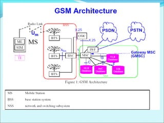
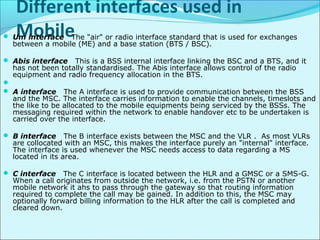
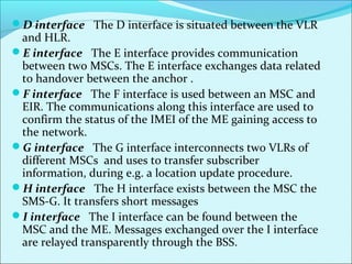
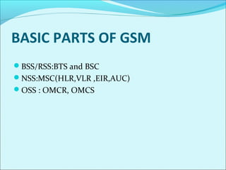
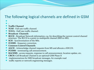
System for Mobile
communications
What is GSM?
Evolution of GSM.
Fundamental of GSM
Architecture of GSM
Establishment of Network
Fundamental of Radio Propagation
Call flow
What is GSM?
The Global System for Mobile communications is a
digital cellular communications system. It was
developed in order to create a common European
mobile telephone standard but it has been rapidly
accepted worldwide.
Formerly it was Groupe Spéciale Mobile (founded
1982)
now: Global System for Mobile Communication
Evolution of GSM.
The idea of cell-based mobile radio systems appeared
at Bell Laboratories (in USA) in the early 1970s.
However, mobile cellular systems were not
introduced for commercial use until the 1980s.
But in the beginnings of cellular systems, each country
developed its own system, which was an undesirable
situation for the following reasons:
The equipment was limited to operate only within
the boundaries of each country.
The market for each mobile equipment was limited.
In order to overcome these problems, the Conference of
European Posts and telecommunications (CEPT) formed,
in 1982 ,the Group Special Mobile (GSM) in order to
develop a pan-European mobile cellular radio system . The
standardized system had to meet certain criteria:
Spectrum efficiency
International roaming
Low mobile and base stations costs
Good subjective voice quality
Compatibility with other systems such as ISDN
(Integrated Services Digital Network)
Ability to support new services
YEAR EVENT TOOK PLACE
1982 CEPT establishes a GSM group in order to develop the standards for a pan-
European cellular mobile system
CEPT adopts WARC 79 recommendation allocating 890-915 MHz and
935-960 MHz for land mobile
GSM created to set standard
1985 Adoption of a list of recommendations to be generated by the group
1987 Digital Technology standards set for TDMA, speech coding, channel:
and modulation method.
Telecommunication carriers from 14 European countries sign
Memorandum of Understanding (MOU) and agree to install system in
1991
1988 Industrial development started
1989 Acceptance of GSM-1800 system, with GSM as standard
1991 First system deployed (July)
1992 First GSM terminals receive interim type approval
1993 First GSM-1800 network launched
1995 First GSM-1900 network in US & Canada
GENERATION OF GSM
1st
generation:- Analog mobile technologies :- AMPS , TACS & NMT.
2nd
generation:- digital mobile technologies :- GSM , CDMA
2.5generation:- Enhancement of GSM:- GPRS
3rd
generation:- Technologies coursed by ITU-IMT
The following table lists the key events in the GSM evolution
 AMPS—Advanced Mobile Phone System
 TACS----Total Access Communication System.
 NMT----Nordic Mobile Telephones
GSM
EDGE
2.5 G
GPRS
2G
2.5 g+
UMTS 3G
WCDMA
GPRS-Wireless Data Services .
EDGE—Provides 3 times the data capacity of GPRS.
3G---Uses WCDMA technologies Over Air interface
(5MHz).
GSM STANDARDSGSM-900 Standard
The GSM-900 standard is a standard for digital voice transmission in the 900
MHz band. This so called “primary band" includes two sub bands of 25 MHz
GSM-1800 Standard
In GSM-1800, 1800 MHz band was allocated for digital mobile telephone
services which has frequency of 75 MHz. This was three times the bandwidth
allocated for GSM-900.
GSM-1900 Standard
GSM-1900 is the standard for the 1900MHz band. It includes the same
network component as the GSM-900 or GSM-1800. The band width of this
standard is 60 MHz.
GSM Channels/Carriers
The following table will show the channels and carriers of different GSM models
P-
GSM(Pri
mary-
GSM)
900
E-GSM
900(Exte
nded-
GSM)
R-GSM
900(Rail
ways-
GSM)
GSM
1800
GSM
1900
Uplink frequency 890-915
MHz
880-915
MHz
886-915
MHz
1710-
1785
MHz
1850-
1910
MHz
Down link
frequency
935-960
MHz
925-960
MHz
931-960
MHz
1805-
1855
MHz
1930-
1990
MHz
Channel spacing 200 kHz 200 kHz 200 kHz 200
kHz
200 kHz
Carrier
Frequency
124 174 144 374 299
Duplex spacing 45 MHZ 45 MHZ 45 MHZ 95
MHZ
80 MHZ
Type of access Technology
FDMA (Frequency division Multiple Access):- In FDMA,
signals from various users are assigned different frequencies.
Frequency guard bands are maintained between adjacent
signal spectra to minimize crosstalk between channels.
TDMA (TIME DIVISION MULTIPLE ACCESS):- In a
TDMA system, data from each user is conveyed in time
intervals called “Time slots”. Several slots make up a
frame . Each slot is made up of a preamble plus information
bits addressed to various stations .the functions of the
preamble are to provide identification and incidental
information and to allow synchronization of the slot at the
intended receiver .Guard times are used between each user’s
transmission to minimize crosstalk between channels.
GSM NUMBERING STRUCTURE:
MSISDN :- The real telephone number of a mobile station
is the mobile subscriber ISDN number (MSISDN). It is
assigned to the subscriber (his or her SIM, respectively),
such that a mobile station set can have several MSISDNs
depending on the SIM. - CC+NDC+SN - 12digits
IMSI - Each registered user is uniquely identified by its
international mobile subscriber identity (IMSI). It is stored
in the subscriber identity module (SIM) A mobile station
can only be operated if a SIM with a valid IMSI is inserted
into equipment with a valid IMEI. MCC (3)+MNC
(2)+MSIN (10) - 15 digits
TMSI - The VLR, which is responsible for the current location
of a subscriber, can assign a temporary mobile subscriber
identity (TMSI) which has only local significance in the area
handled by the VLR. It is stored on the network side only in the
VLR and is not passed to the HLR. 4 octets
IMEI - The international mobile station equipment identity
(IMEI) uniquely identifies a mobile station internationally. It is
a kind of serial number. The IMEI is allocated by the equipment
manufacturer and registered by the network operator and
registered by the network operator who stores it in the EIR. By
means of IMEI one recognizes obsolete, stolen or nonfunctional
equipment. TAC+FAC+SNR+Spare - 15 digits
LAI - Each LA of an PLMN has its own identifier. The Location
Area Identifier (LAI) is also structured hierarchically and
internationally unique as follows: MCC+MNC+LAC
GSM Multiplex structure
GSM works on a combination of frequency-division
multiplexing and time-division multiplexing for providing
multiple access by mobile stations.

 GSM utilizes a cellular concept, in which a
geographical area is divided into planned radio cells , with
one BTS per cell with which a mobile can make contact.
The radio cells, each having the exclusive use of specific
FDM channels. The same frequencies are only used after
sufficiently long distances in neighboring cell clusters. The
cell radius can vary according to user density from 300
mtrs to 35 Kms.

Cells
Different interfaces used in
Mobile Um interface The "air" or radio interface standard that is used for exchanges
between a mobile (ME) and a base station (BTS / BSC).
 Abis interface This is a BSS internal interface linking the BSC and a BTS, and it
has not been totally standardised. The Abis interface allows control of the radio
equipment and radio frequency allocation in the BTS.

 A interface The A interface is used to provide communication between the BSS
and the MSC. The interface carries information to enable the channels, timeslots and
the like to be allocated to the mobile equipments being serviced by the BSSs. The
messaging required within the network to enable handover etc to be undertaken is
carried over the interface.
 B interface The B interface exists between the MSC and the VLR . As most VLRs
are collocated with an MSC, this makes the interface purely an "internal" interface.
The interface is used whenever the MSC needs access to data regarding a MS
located in its area.
 C interface The C interface is located between the HLR and a GMSC or a SMS-G.
When a call originates from outside the network, i.e. from the PSTN or another
mobile network it ahs to pass through the gateway so that routing information
required to complete the call may be gained. In addition to this, the MSC may
optionally forward billing information to the HLR after the call is completed and
cleared down.
D interface The D interface is situated between the VLR
and HLR.
E interface The E interface provides communication
between two MSCs. The E interface exchanges data related
to handover between the anchor .
F interface The F interface is used between an MSC and
EIR. The communications along this interface are used to
confirm the status of the IMEI of the ME gaining access to
the network.
G interface The G interface interconnects two VLRs of
different MSCs and uses to transfer subscriber
information, during e.g. a location update procedure.
H interface The H interface exists between the MSC the
SMS-G. It transfers short messages
I interface The I interface can be found between the
MSC and the ME. Messages exchanged over the I interface
are relayed transparently through the BSS.
BASIC PARTS OF GSM
BSS/RSS:BTS and BSC
NSS:MSC(HLR,VLR ,EIR,AUC)
OSS : OMCR, OMCS
Mobile station(MS)The mobile station (MS) represents the terminal equipment used by the wireless
subscriber supported by the GSM Wireless system. Man machine interface. The
SIM may be a removable module, while the equipment identity is not linked to a
particular subscriber.
 Functions of a Mobile Station :-
 Radio transmission termination. Radio Channel Management.
 Speech Encoding/Decoding .Radio Link error Protection.
 Flow control of data. Mobility Management.
 SIM (Subscriber identity Module) - It is basically a removable smart card in
compliance with the ISO 7816 standard and a plug-in module (25 x 15 mm) .It
includes a microprocessor with all the subscriber-related information . SIM (and
consequently MS) is protected by a Personal Identification Number (PIN). It has a
PIN Unblocking Key (PUK) used to unblock it.

 Information stored in a SIM card- Serial number
 International Mobile Subscriber Identity (IMSI)
 Security authentication and cyphering information
 Temporary Network information (LAI, TMSI)
 List of services subscribed by the user
BSSThe BSS is responsible for communicating with mobile stations in cell areas.
BTS is a network element with transmission and reception devices (transceivers) to
and from the MS, including
 antennas
 signal processing specific devices for the Air interface management
 It can be considered as a complex radio modem controlled by the BSC
 It is involved also in the transmission and reception with the BSC through the A-
bis interface
 It has just executive functions (no management
 Function
 Broadcast/receive to/from the MS either signalling and traffic signals
 Perform source and channel coding
 Modulate/Demodulate signals to be broadcasted/received through the Air
interface radio channel
 Multiplex the information to be transmitted over each carrier.
BSC One BSC controls one or more BTS’s and can perform
inter-BTS and intra-BTS handover.

BSC Function
Control and supervise the BTSs
Configure each cell with the allocation and the release of traffic
and signalling channels
Manage the paging operation
Collect the signals quality measures acquired by the BTSs over
the downlink and uplink channels
Manage all the radio interfaces
Manage the handover procedures
Transcode and Sub-multiplex the bit stream
Function of NSS
Call control identification of the subscriber
establishing a call and release of the connection after the call is
over
Mobility management
taking care of the location of the subscribers before, during and
after a call
Collecting the charging information about a call
number of the caller and of the called subscriber
length and type of the provided services
Transfer the acquired charging information to the Billing centre
Signalling with other networks and BSS through the different
interfaces
Subscriber data handling
Data storage permanently or temporarily in some databases
OMCR:- It is used to monitor and maintain the alarms of the
system.
The following logical channels are defined in GSM

 :
 Traffic Channel
 TCHf - Full rate traffic channel.
 TCH h - Half rate traffic channel.
 Broadcast Channels
 BCCH - Broadcast Network information, e.g. for describing the current control channel
structure. The BCCH is a point-to-multipoint channel (BSS-to-MS).
 SCH - Synchronisation of the MSs.
 FCHMS - frequency correction.
 Common Control Channels
 AGCH - Acknowledge channel requests from MS and allocate a SDCCH.
 PCHMS - terminating call announcement.
 RACHMS - access requests, response to call announcement, location update, etc.
 CBCH: Cell Broadcast Channel is an optional GSM Phase II
 implementations for SMS broadcast messages, for example road
 traffic reports or network engineering messages.
NCH: Used for GSM Phase II voice services such as Voice Broadcast
Service (VBS) or Voice Group Calling Service (VGCS
Dedicated Control Channels
DCCH comprise the following bi-directional (uplink / downlink)
point to point control channels:
SDCCH - For signalling exchanges, e.g. during call setup,
registration / location updates.

FACCHs - FACCH for the SDCCH. The SDCCH burst is stolen for a
full signalling burst. Function not clear in the present version of GSM
(could be used for e.g. handover of an eight-rate channel, i.e. using a
"SDCCH-like" channel for other purposes than signalling).
SACCHs - SDCCH in-band signalling, e.g. for link monitoring
Types of GSM handover
 Within the GSM system there are four types of handover that can be
performed for GSM only systems:
 Intra-BTS handover: This form of GSM handover occurs if it is required to
change the frequency or slot being used by a mobile because of interference,
or other reasons. In this form of GSM handover, the mobile remains attached
to the same base station transceiver, but changes the channel or slot.
 Inter-BTS Intra BSC handover: This for of GSM handover or GSM handoff
occurs when the mobile moves out of the coverage area of one BTS but into
another controlled by the same BSC. In this instance the BSC is able to
perform the handover and it assigns a new channel and slot to the mobile,
before releasing the old BTS from communicating with the mobile.
 Inter-BSC handover: When the mobile moves out of the range of cells
controlled by one BSC, a more involved form of handover has to be
performed, handing over not only from one BTS to another but one BSC to
another. For this the handover is controlled by the MSC.
 Inter-MSC handover: This form of handover occurs when changing
between networks. The two MSCs involved negotiate to control the handover

Gsm overview

  • 1.
  • 2.
    What is GSM? Evolutionof GSM. Fundamental of GSM Architecture of GSM Establishment of Network Fundamental of Radio Propagation Call flow
  • 3.
    What is GSM? TheGlobal System for Mobile communications is a digital cellular communications system. It was developed in order to create a common European mobile telephone standard but it has been rapidly accepted worldwide. Formerly it was Groupe Spéciale Mobile (founded 1982) now: Global System for Mobile Communication
  • 4.
    Evolution of GSM. Theidea of cell-based mobile radio systems appeared at Bell Laboratories (in USA) in the early 1970s. However, mobile cellular systems were not introduced for commercial use until the 1980s. But in the beginnings of cellular systems, each country developed its own system, which was an undesirable situation for the following reasons: The equipment was limited to operate only within the boundaries of each country. The market for each mobile equipment was limited.
  • 5.
    In order toovercome these problems, the Conference of European Posts and telecommunications (CEPT) formed, in 1982 ,the Group Special Mobile (GSM) in order to develop a pan-European mobile cellular radio system . The standardized system had to meet certain criteria: Spectrum efficiency International roaming Low mobile and base stations costs Good subjective voice quality Compatibility with other systems such as ISDN (Integrated Services Digital Network) Ability to support new services
  • 6.
    YEAR EVENT TOOKPLACE 1982 CEPT establishes a GSM group in order to develop the standards for a pan- European cellular mobile system CEPT adopts WARC 79 recommendation allocating 890-915 MHz and 935-960 MHz for land mobile GSM created to set standard 1985 Adoption of a list of recommendations to be generated by the group 1987 Digital Technology standards set for TDMA, speech coding, channel: and modulation method. Telecommunication carriers from 14 European countries sign Memorandum of Understanding (MOU) and agree to install system in 1991 1988 Industrial development started 1989 Acceptance of GSM-1800 system, with GSM as standard 1991 First system deployed (July) 1992 First GSM terminals receive interim type approval 1993 First GSM-1800 network launched 1995 First GSM-1900 network in US & Canada
  • 7.
    GENERATION OF GSM 1st generation:-Analog mobile technologies :- AMPS , TACS & NMT. 2nd generation:- digital mobile technologies :- GSM , CDMA 2.5generation:- Enhancement of GSM:- GPRS 3rd generation:- Technologies coursed by ITU-IMT The following table lists the key events in the GSM evolution  AMPS—Advanced Mobile Phone System  TACS----Total Access Communication System.  NMT----Nordic Mobile Telephones
  • 8.
  • 9.
    GPRS-Wireless Data Services. EDGE—Provides 3 times the data capacity of GPRS. 3G---Uses WCDMA technologies Over Air interface (5MHz).
  • 10.
    GSM STANDARDSGSM-900 Standard TheGSM-900 standard is a standard for digital voice transmission in the 900 MHz band. This so called “primary band" includes two sub bands of 25 MHz GSM-1800 Standard In GSM-1800, 1800 MHz band was allocated for digital mobile telephone services which has frequency of 75 MHz. This was three times the bandwidth allocated for GSM-900. GSM-1900 Standard GSM-1900 is the standard for the 1900MHz band. It includes the same network component as the GSM-900 or GSM-1800. The band width of this standard is 60 MHz. GSM Channels/Carriers The following table will show the channels and carriers of different GSM models
  • 11.
    P- GSM(Pri mary- GSM) 900 E-GSM 900(Exte nded- GSM) R-GSM 900(Rail ways- GSM) GSM 1800 GSM 1900 Uplink frequency 890-915 MHz 880-915 MHz 886-915 MHz 1710- 1785 MHz 1850- 1910 MHz Downlink frequency 935-960 MHz 925-960 MHz 931-960 MHz 1805- 1855 MHz 1930- 1990 MHz Channel spacing 200 kHz 200 kHz 200 kHz 200 kHz 200 kHz Carrier Frequency 124 174 144 374 299 Duplex spacing 45 MHZ 45 MHZ 45 MHZ 95 MHZ 80 MHZ
  • 12.
    Type of accessTechnology FDMA (Frequency division Multiple Access):- In FDMA, signals from various users are assigned different frequencies. Frequency guard bands are maintained between adjacent signal spectra to minimize crosstalk between channels. TDMA (TIME DIVISION MULTIPLE ACCESS):- In a TDMA system, data from each user is conveyed in time intervals called “Time slots”. Several slots make up a frame . Each slot is made up of a preamble plus information bits addressed to various stations .the functions of the preamble are to provide identification and incidental information and to allow synchronization of the slot at the intended receiver .Guard times are used between each user’s transmission to minimize crosstalk between channels.
  • 13.
    GSM NUMBERING STRUCTURE: MSISDN:- The real telephone number of a mobile station is the mobile subscriber ISDN number (MSISDN). It is assigned to the subscriber (his or her SIM, respectively), such that a mobile station set can have several MSISDNs depending on the SIM. - CC+NDC+SN - 12digits IMSI - Each registered user is uniquely identified by its international mobile subscriber identity (IMSI). It is stored in the subscriber identity module (SIM) A mobile station can only be operated if a SIM with a valid IMSI is inserted into equipment with a valid IMEI. MCC (3)+MNC (2)+MSIN (10) - 15 digits
  • 14.
    TMSI - TheVLR, which is responsible for the current location of a subscriber, can assign a temporary mobile subscriber identity (TMSI) which has only local significance in the area handled by the VLR. It is stored on the network side only in the VLR and is not passed to the HLR. 4 octets IMEI - The international mobile station equipment identity (IMEI) uniquely identifies a mobile station internationally. It is a kind of serial number. The IMEI is allocated by the equipment manufacturer and registered by the network operator and registered by the network operator who stores it in the EIR. By means of IMEI one recognizes obsolete, stolen or nonfunctional equipment. TAC+FAC+SNR+Spare - 15 digits LAI - Each LA of an PLMN has its own identifier. The Location Area Identifier (LAI) is also structured hierarchically and internationally unique as follows: MCC+MNC+LAC
  • 15.
    GSM Multiplex structure GSMworks on a combination of frequency-division multiplexing and time-division multiplexing for providing multiple access by mobile stations.   GSM utilizes a cellular concept, in which a geographical area is divided into planned radio cells , with one BTS per cell with which a mobile can make contact. The radio cells, each having the exclusive use of specific FDM channels. The same frequencies are only used after sufficiently long distances in neighboring cell clusters. The cell radius can vary according to user density from 300 mtrs to 35 Kms. 
  • 16.
  • 19.
    Different interfaces usedin Mobile Um interface The "air" or radio interface standard that is used for exchanges between a mobile (ME) and a base station (BTS / BSC).  Abis interface This is a BSS internal interface linking the BSC and a BTS, and it has not been totally standardised. The Abis interface allows control of the radio equipment and radio frequency allocation in the BTS.   A interface The A interface is used to provide communication between the BSS and the MSC. The interface carries information to enable the channels, timeslots and the like to be allocated to the mobile equipments being serviced by the BSSs. The messaging required within the network to enable handover etc to be undertaken is carried over the interface.  B interface The B interface exists between the MSC and the VLR . As most VLRs are collocated with an MSC, this makes the interface purely an "internal" interface. The interface is used whenever the MSC needs access to data regarding a MS located in its area.  C interface The C interface is located between the HLR and a GMSC or a SMS-G. When a call originates from outside the network, i.e. from the PSTN or another mobile network it ahs to pass through the gateway so that routing information required to complete the call may be gained. In addition to this, the MSC may optionally forward billing information to the HLR after the call is completed and cleared down.
  • 20.
    D interface TheD interface is situated between the VLR and HLR. E interface The E interface provides communication between two MSCs. The E interface exchanges data related to handover between the anchor . F interface The F interface is used between an MSC and EIR. The communications along this interface are used to confirm the status of the IMEI of the ME gaining access to the network. G interface The G interface interconnects two VLRs of different MSCs and uses to transfer subscriber information, during e.g. a location update procedure. H interface The H interface exists between the MSC the SMS-G. It transfers short messages I interface The I interface can be found between the MSC and the ME. Messages exchanged over the I interface are relayed transparently through the BSS.
  • 21.
    BASIC PARTS OFGSM BSS/RSS:BTS and BSC NSS:MSC(HLR,VLR ,EIR,AUC) OSS : OMCR, OMCS
  • 22.
    Mobile station(MS)The mobilestation (MS) represents the terminal equipment used by the wireless subscriber supported by the GSM Wireless system. Man machine interface. The SIM may be a removable module, while the equipment identity is not linked to a particular subscriber.  Functions of a Mobile Station :-  Radio transmission termination. Radio Channel Management.  Speech Encoding/Decoding .Radio Link error Protection.  Flow control of data. Mobility Management.  SIM (Subscriber identity Module) - It is basically a removable smart card in compliance with the ISO 7816 standard and a plug-in module (25 x 15 mm) .It includes a microprocessor with all the subscriber-related information . SIM (and consequently MS) is protected by a Personal Identification Number (PIN). It has a PIN Unblocking Key (PUK) used to unblock it.   Information stored in a SIM card- Serial number  International Mobile Subscriber Identity (IMSI)  Security authentication and cyphering information  Temporary Network information (LAI, TMSI)  List of services subscribed by the user
  • 23.
    BSSThe BSS isresponsible for communicating with mobile stations in cell areas. BTS is a network element with transmission and reception devices (transceivers) to and from the MS, including  antennas  signal processing specific devices for the Air interface management  It can be considered as a complex radio modem controlled by the BSC  It is involved also in the transmission and reception with the BSC through the A- bis interface  It has just executive functions (no management  Function  Broadcast/receive to/from the MS either signalling and traffic signals  Perform source and channel coding  Modulate/Demodulate signals to be broadcasted/received through the Air interface radio channel  Multiplex the information to be transmitted over each carrier.
  • 24.
    BSC One BSCcontrols one or more BTS’s and can perform inter-BTS and intra-BTS handover.  BSC Function Control and supervise the BTSs Configure each cell with the allocation and the release of traffic and signalling channels Manage the paging operation Collect the signals quality measures acquired by the BTSs over the downlink and uplink channels Manage all the radio interfaces Manage the handover procedures Transcode and Sub-multiplex the bit stream
  • 25.
    Function of NSS Callcontrol identification of the subscriber establishing a call and release of the connection after the call is over Mobility management taking care of the location of the subscribers before, during and after a call Collecting the charging information about a call number of the caller and of the called subscriber length and type of the provided services Transfer the acquired charging information to the Billing centre Signalling with other networks and BSS through the different interfaces Subscriber data handling Data storage permanently or temporarily in some databases OMCR:- It is used to monitor and maintain the alarms of the system.
  • 28.
    The following logicalchannels are defined in GSM   :  Traffic Channel  TCHf - Full rate traffic channel.  TCH h - Half rate traffic channel.  Broadcast Channels  BCCH - Broadcast Network information, e.g. for describing the current control channel structure. The BCCH is a point-to-multipoint channel (BSS-to-MS).  SCH - Synchronisation of the MSs.  FCHMS - frequency correction.  Common Control Channels  AGCH - Acknowledge channel requests from MS and allocate a SDCCH.  PCHMS - terminating call announcement.  RACHMS - access requests, response to call announcement, location update, etc.  CBCH: Cell Broadcast Channel is an optional GSM Phase II  implementations for SMS broadcast messages, for example road  traffic reports or network engineering messages.
  • 29.
    NCH: Used forGSM Phase II voice services such as Voice Broadcast Service (VBS) or Voice Group Calling Service (VGCS Dedicated Control Channels DCCH comprise the following bi-directional (uplink / downlink) point to point control channels: SDCCH - For signalling exchanges, e.g. during call setup, registration / location updates.  FACCHs - FACCH for the SDCCH. The SDCCH burst is stolen for a full signalling burst. Function not clear in the present version of GSM (could be used for e.g. handover of an eight-rate channel, i.e. using a "SDCCH-like" channel for other purposes than signalling). SACCHs - SDCCH in-band signalling, e.g. for link monitoring
  • 30.
    Types of GSMhandover  Within the GSM system there are four types of handover that can be performed for GSM only systems:  Intra-BTS handover: This form of GSM handover occurs if it is required to change the frequency or slot being used by a mobile because of interference, or other reasons. In this form of GSM handover, the mobile remains attached to the same base station transceiver, but changes the channel or slot.  Inter-BTS Intra BSC handover: This for of GSM handover or GSM handoff occurs when the mobile moves out of the coverage area of one BTS but into another controlled by the same BSC. In this instance the BSC is able to perform the handover and it assigns a new channel and slot to the mobile, before releasing the old BTS from communicating with the mobile.  Inter-BSC handover: When the mobile moves out of the range of cells controlled by one BSC, a more involved form of handover has to be performed, handing over not only from one BTS to another but one BSC to another. For this the handover is controlled by the MSC.  Inter-MSC handover: This form of handover occurs when changing between networks. The two MSCs involved negotiate to control the handover