This document discusses various topics related to transmission characteristics of optical fibers, including:
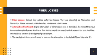
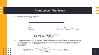
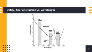
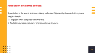
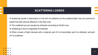
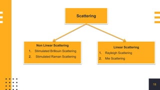
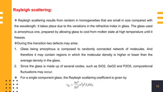
- The main types of losses in optical fibers are attenuation due to absorption and scattering. Absorption includes material absorption from defects, ions, and molecular vibrations. Scattering includes Rayleigh and Mie scattering.
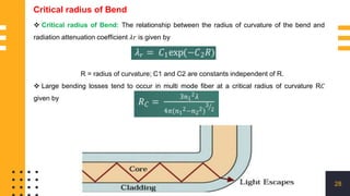
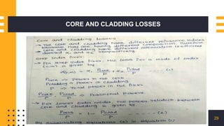
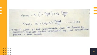
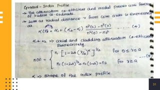
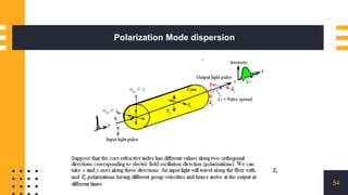
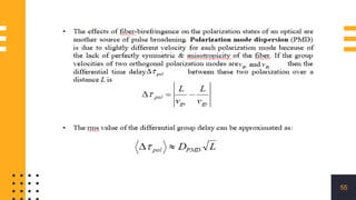
- Other losses include bending losses from micro- and macro-bends, core-cladding losses, and polarization mode dispersion.
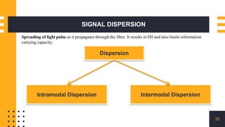
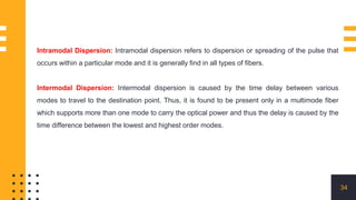
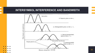
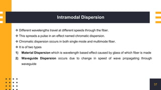
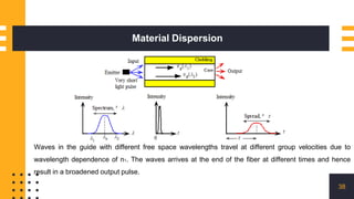
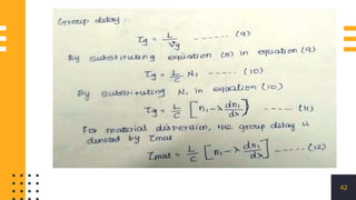
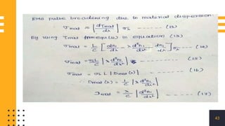
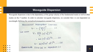
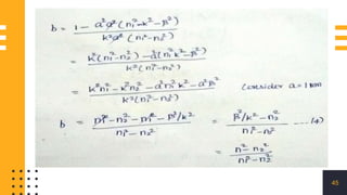
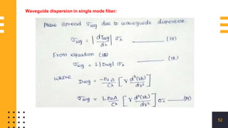
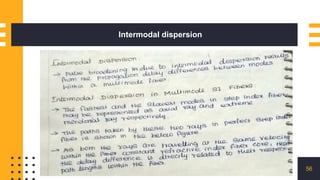
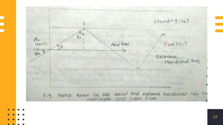
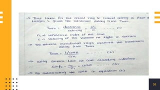
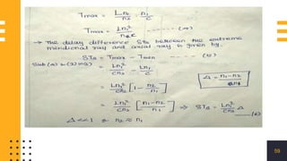
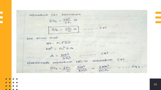
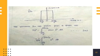
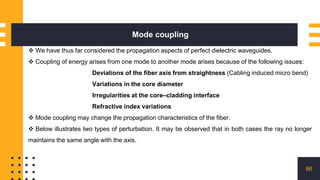
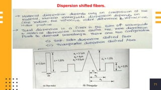
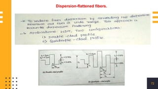
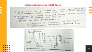
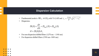
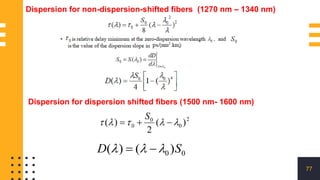
- Signal dispersion spreads optical pulses as they propagate and can cause intersymbol interference. The main types are material dispersion, waveguide dispersion, modal dispersion, and polarization mode dispersion.
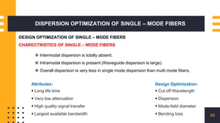
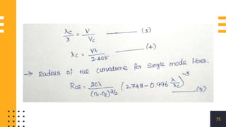
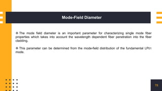
- Design of single mode fibers aims to optimize parameters like cutoff wavelength, dispersion, mode field diameter
Optical fibers are thin glass rods wrapped in plastic that are used to transmit light signals for applications such as high-speed internet, telecommunications, endoscopy, and microscopy. They allow transmission of data over longer distances and in places where copper wires cannot reach. Optical fibers work via the phenomenon of total internal reflection, where light bouncing around the higher refractive index glass core is reflected back in rather than escaping at the lower refractive index cladding.
1. Optical fibers transmit data using pulses of light and are able to carry much higher bandwidths than metal wires.
2. Fibers use total internal reflection to guide light along their length with less loss than wires and are immune to electromagnetic interference.
3. Fibers have various applications including long distance communications, local networks, imaging bundles, and sensors.
Fibre optics are thin strands of glass that transmit light signals over long distances. They have a core that transmits light surrounded by cladding that reflects light to prevent signal degradation. Advantages include low cost, high bandwidth, security and immunity to electromagnetic interference. Disadvantages include cost of installation, fragility and susceptibility to chemicals. Fibre optics have become widespread due to their use in telecommunications.
The document provides an overview of fiber optic technology including:
- The basics of how optical fibers transmit light via total internal reflection
- The different types of optical fibers like single-mode, multi-mode, and their variations
- Components used in fiber optic systems like connectors, adapters, splitters, and attenuators
- Causes of loss in optical fibers including absorption, scattering, modal dispersion, and more
- Applications of fiber optics in telecommunications, networks, and more
2015 D-STOP Symposium session by Robert Heath, UT Austin's Wireless Networking & Communications Group.
Get symposium details: http://ctr.utexas.edu/research/d-stop/education/annual-symposium/
This document provides an introduction to dense wavelength division multiplexing (DWDM) including:
1. DWDM allows multiple optical channels to be transmitted over a single fiber, increasing network capacity and scalability. It enables transmission of terabits of data over long distances without regeneration.
2. Key concepts in optical transmission are explained, including wavelength bands, fiber attenuation, dispersion, and nonlinear effects.
3. The development of single-mode fiber is summarized, from early multimode fiber to modern low-dispersion fiber designs.
This document discusses optical fiber splicing. It describes three main splicing methods - de-matable connectors, mechanical splices, and fusion splices. Mechanical splices have higher losses than fusion splices. Fusion splicing welds two fibers together using an electric arc and provides the lowest loss. The document outlines intrinsic and extrinsic factors that contribute to splice loss and describes the fiber preparation, alignment, and fusion steps for fusion splicing. Fusion splicing is considered the most reliable and widely used splicing method when performed properly.
This document provides an overview of fibre optics, including its composition, operation, advantages, disadvantages, types of communication, cable types, pulse spreading, transmission loss, and conclusions. Fibre optics uses glass or plastic filaments to transmit light signals for communication. It has advantages over metal cables like greater bandwidth, less signal degradation, lighter weight, and security. Installation is more expensive than metal cables. Fibre optics enables both analog and digital communication and comes in step index or graded index cable types.
Free space optical communication (FSO) uses lasers and photo detectors to transmit data through the air without fiber cables. It was initially developed by NASA and the military. FSO can transmit data, voice, or video at speeds up to 1.25 Gbps using invisible beams of light in a line-of-sight system. Signal propagation is impacted by weather like fog and rain, which can cause scattering and absorption leading to power losses and interruptions. While installation has low costs compared to fiber, FSO performance depends on clear line-of-sight conditions.
The document discusses the history and principles of fiber optics. It begins by describing how John Tyndall first demonstrated light guidance through water in 1870. It then discusses the key developments in flexible fiberscopes in the 1950s and theories of light propagation in glass fibers in the 1960s. The document outlines the core components and structures of optical fibers, including the core, cladding and buffer coating. It explains the principles of total internal reflection that allow fibers to guide light signals. Finally, it discusses important fiber optic concepts like acceptance angle and numerical aperture.
Optical fiber is a flexible transparent fiber made of glass or plastic that transmits light and is used for fiber-optic communication. It consists of a core that light travels through, surrounded by cladding and a protective buffer coating. Light is reflected down the fiber by the coating and emerges from the other end with little loss. Optical fiber has advantages over copper wire like higher bandwidth, less signal degradation over longer distances, and non-flammability. Common applications include use by cable companies, utilities, LANs, and broadcasting.
Optical fibers carry light along their length and are used for fiber-optic communications. They allow transmission over longer distances and higher data rates than other forms of communication. Fibers have a glass or plastic core that carries light through total internal reflection. They are used for long-distance communication networks, local area networks, and other applications due to advantages over metal wires like lower loss and immunity to electromagnetic interference.
A brief presentation about optical fiber technology. Presented by Abdessalam BENHARIRA and Laurent PANEK.
Summary
1. What is optical fiber ?
2. How it works ?
3. Different types
4. Uses
5. Advantages and disadvantages
6. Conclusion
O documento discute a tecnologia SDH (Synchronous Digital Hierarchy), que supera os problemas das redes PDH antigas. O SDH introduz um quadro com estrutura de payload para transporte de dados e overhead para gerenciamento e manutenção da rede, permitindo uma única infraestrutura flexível. O primeiro padrão SDH foi aprovado em 1988 e é usado globalmente, com SONET sendo o equivalente na América do Norte.
Dense wavelength division multiplexing (DWDM) is a fiber optic transmission technique that employs light wavelengths to transmit data parallel-by-bit or serial-by-character. It allows for increased fiber capacity and scalability. DWDM evolved from earlier WDM techniques and can transmit 64 or more channels through a single fiber using spacing between 25-50 GHz. Ongoing research focuses on reducing dispersion and developing tunable lasers. DWDM provides a robust, simple, and cost-effective solution for growing bandwidth demands.
Optical fiber is a flexible transparent fiber made of high quality glass or plastic that transmits light between two ends. It functions as a waveguide or light pipe. Optical fibers are widely used for fiber optic communications due to their ability to transmit signals over longer distances and higher bandwidths compared to other forms of communication. Fibers are used instead of metal wires because signals travel along them with less loss and are safe from electromagnetic interference. Optical fibers have been used for communication since the 1840s and are now used for transmitting data at rates as high as 400 gigabits per second. Optical fiber provides benefits such as greater bandwidth, immunity to electrical interference, and lower signal attenuation over long distances compared to conventional copper cables.
Visible light communication (vlc) systemsCKSunith1
Visible light communication (VLC) uses visible light spectrum between 390-750nm for data transmission. It can provide huge bandwidth for multi-gigabit data rates. VLC systems consist of LED lights that act as transmitters and photodiodes as receivers. Common modulation techniques for VLC include on-off keying and pulse-based modulations. VLC provides advantages like unlimited bandwidth, low power consumption, security and indoor positioning. Challenges include flicker mitigation and multipath interference. Standards like IEEE 802.15.7 specify the physical and MAC layers to address these challenges.
Fiber optics use thin strands of glass called optical fibers to transmit light signals over long distances. Light travels through the core of the fiber, which is surrounded by cladding that reflects the light down the length of the fiber. Fiber optic systems include a transmitter that produces light signals, the optical fiber that carries the signals, and a receiver that interprets the signals. Fiber optics have advantages over metal wires like lower costs, higher data capacity, and less signal degradation over long distances.
Optical fibers transmit light signals over long distances for communication purposes. They have a thin glass core surrounded by cladding and a protective buffer coating. Total internal reflection allows light to be transmitted through the core without loss. Optical fibers come in single-mode and multi-mode varieties and are used for applications like telephone networks, cable TV, and data transmission. Their advantages include high bandwidth, low signal degradation, and small size. Disadvantages include high installation costs and fragility.
A directional coupler is used to combine and split optical signals. It consists of two input ports and two output ports. A 2x2 coupler splits the power from each input port between the two output ports. Star couplers combine multiple signals and broadcast them to many outputs. Isolators allow transmission in one direction but block transmission in the opposite direction, while circulators transmit signals between ports in a circular fashion. Multiplexers and demultiplexers combine and separate different wavelengths in WDM systems using interference filters such as arrayed waveguide gratings.
After our successful launch of '5G for Absolute Beginners' course (http://bit.ly/5Gbegins) in 2020, we decided to create an introductory training course on 6G Mobile Wireless Communications technology. The course is ready and the best way to navigate it is via the Free 6G Training page at: https://bit.ly/6Gintro - this will ensure that you have the latest version of each video and also the most recent version of the 6G technologies videos as and they are added.
In this part we will look at what we call the 6G Devices but they are effectively the devices that will exist in 2030. Some of them will be new form factors while others would be evolution of the existing form factors. These will include wearables, hearable and a lot of new innovation that are in initial phase of development. We will also spend some time on the futuristic XR headsets as they will definitely have a big role to plan in Beyond 5G and 6G timeframe.
This course is part of #Free6Gtraining initiative (https://www.free6gtraining.com/)
All our #3G4G5G slides and videos are available at:
Videos: https://www.youtube.com/3G4G5G
Slides: https://www.slideshare.net/3G4GLtd
6G and Beyond-5G Page: https://www.3g4g.co.uk/6G/
Free Training Videos: https://www.3g4g.co.uk/Training/
Free 6G Training Blog: https://www.free6gtraining.com/
Study on Laser Communication: Features, Application, Advantagesijtsrd
Laser communications offer a viable alternative to RF communications for intersatellite links and other applications where high-performance links are necessary. High data rate, small antenna size, narrow beam divergence, and a narrow field of view are characteristics of laser communication that offer a number of potential advantages for system design. The high data rate and large information throughput available with laser communications are many times greater than in radio frequency (RF) systems. The small antenna size requires only a small increase in the weight and volume of host vehicle. In addition, this feature substantially reduces blockage of fields of view of the most desirable areas on satellites. The smaller antennas, with diameters typically less than 30cm, create less momentum disturbance to any sensitive satellite sensors. The narrow beam divergence of affords interference-free and secure operation. Prof. Atul A. Padghan | Prof. Ankit P. Jaiswal"Study on Laser Communication: Features, Application, Advantages" Published in International Journal of Trend in Scientific Research and Development (ijtsrd), ISSN: 2456-6470, Volume-2 | Issue-3 , April 2018, URL: http://www.ijtsrd.com/papers/ijtsrd10798.pdf http://www.ijtsrd.com/engineering/electronics-and-communication-engineering/10798/study-on-laser-communication-features-application-advantages/prof-atul-a-padghan
This document summarizes a technical seminar on free space optics (FSO) presented by Kartik K Benageri at Jain Institute of Technology in Davangere, Karnataka, India. The seminar covered the introduction, key features, working principles, advantages, limitations, and conclusions of FSO technology. FSO uses lasers and photo detectors to transmit data, voice, or video at speeds up to 2.5 Gbps in a line-of-sight fashion without the need for fiber. While offering benefits like flexibility, low cost, and security compared to fiber or microwave, FSO performance can be impacted by environmental factors like fog, rain, scattering, and building sway. The seminar provided information
Optical fiber Communication training reporthuzaifa027
This document provides a table of contents and index for a report on optical fiber cables. It includes 8 chapters that cover topics such as the history of optical fiber cables, how they work, different types of optical fibers and cables, optical networks, fiber optic installation, splicing, power measurement, and conclusions. The document provides an overview of the contents and organization of the technical report on optical fiber cables.
This document discusses different types of optical fibers. It begins by outlining the evolution of optical fiber technology from 1880 to 1980. It then defines an optical fiber as a thin cylindrical fiber of glass that transmits light via total internal reflection. The structure of an optical fiber is described as having a core that carries light, a cladding with a lower refractive index than the core, and a buffer coating. Optical fibers are classified based on the number of propagation modes as either single-mode or multi-mode fibers, and based on refractive index profile as either step-index or graded-index fibers.
Fibre optic cables experience losses from attenuation and dispersion. Attenuation includes material absorption from intrinsic effects like electronic and molecular vibrations, and extrinsic effects like impurities. Scattering losses occur from irregularities causing Rayleigh, Brillouin, Raman, waveguide and Mie scattering. Nonlinear losses include micro/macro bending, leaky modes and mode coupling. Proper fibre design and manufacturing can minimize these losses to support high bandwidth signal transmission.
There are two main types of optical fiber signal loss: scattering and absorption. Scattering losses include Rayleigh scattering caused by molecular irregularities and Mie scattering caused by larger defects. Absorption losses are caused by intrinsic material properties like ultraviolet and infrared absorption in silica glass, as well as extrinsic impurities introduced during manufacturing. Proper fiber design and high material purity can minimize these signal losses to enable effective optical fiber communication.
Opto electronics by er. sanyam s. saini me (reg) 2012-14Sanyam Singh
This document discusses materials used for optical fibers and losses in optical fibers. It describes how silica is commonly used due to its good optical transmission, mechanical strength, and chemical inertness. Fluoride glasses are also mentioned but are difficult to manufacture without crystallization. The main losses discussed are absorption, scattering, and bending losses. Absorption can be intrinsic to the material or due to impurities. Scattering transfers power between modes. Bending losses include macro bending from sharp curves and micro bending from microscopic bends in cables. The wavelength of minimum attenuation is around 1550 nm.
The document discusses signal degradation in optical fibers. It notes that attenuation and distortion limit the distance and capacity of fiber optic communication. Attenuation is the decay of signal strength as light pulses propagate through fiber. It is caused by absorption and scattering from fiber material imperfections. Nearly 90% of attenuation is from Rayleigh scattering, which is dependent on wavelength. Absorption results from defects, impurities in the glass composition, and intrinsic absorption by glass constituents. Radiation exposure can also increase attenuation by damaging the fiber structure.
Signal Degradation In Optical Fiber
Losses in an optical fibre:-
The types of losses in a optical fibre are
Attenuation loss
Absorption
Scattering
Bending loss
Dispersion loss
Coupling loss
Losses in optical fibers include attenuation from absorption and scattering, as well as dispersion effects. Attenuation is caused by absorption of light energy through heating of impurities in the fiber, resulting in a loss of optical power over length. Dispersion causes pulse broadening and occurs from intermodal and intramodal effects such as material and waveguide dispersion. An optical time domain reflectometer (OTDR) can be used to detect faults, splices, and bends in fibers by emitting light pulses and measuring backscattered light over time to map reflections in the fiber.
Losses in optical fibers include attenuation from absorption and scattering, as well as dispersion from material and waveguide effects. Attenuation is caused by absorption of light energy through intrinsic effects like interactions with glass components and extrinsic effects from impurities. Dispersion spreads optical pulses during transmission and has intermodal and intramodal components. An optical time domain reflectometer (OTDR) detects backscattered light to locate faults, splices, and bends in fibers by measuring return time and intensity.
Losses in optical fibers include attenuation from absorption and scattering, as well as dispersion effects. Attenuation is caused by absorption of light energy through heating of impurities in the fiber, resulting in a loss of optical power over length. Dispersion causes pulse broadening and occurs from intermodal and intramodal effects such as material and waveguide dispersion. An optical time domain reflectometer (OTDR) can be used to detect faults, splices, and bends in fibers by emitting light pulses and measuring backscattered light over time.
Unit II- TRANSMISSION CHARACTERISTIC OF OPTICAL FIBER tamil arasan
Attenuation - Absorption losses, Scattering losses, Bending Losses, Core and Cladding losses, Signal Distortion in Optical Wave guides-Information Capacity determination -Group Delay-Material Dispersion, Wave guide Dispersion, Signal distortion in SM fibers-Polarization Mode dispersion, Intermodal dispersion, -Design Optimization of SM fibers-RI profile and cut-off wavelength.
Presentation on Optical Fiber for UG Physics students by Dr. P D Shirbhate assistant Professor, Department of Physics G S Gawande college, Umarkhed Dist Yavatmal.
The document discusses several disadvantages of fiber optic communication systems:
1. Fiber optic systems have high upfront costs due to the expense of installing optical fiber cables compared to copper wiring, though the raw materials are inexpensive.
2. Signal scattering from linear and non-linear effects causes light to transfer between fiber modes, reducing the strength of the transmitted signal over long distances.
3. Optical fibers are susceptible to additional signal loss if bent below their minimum bend radius, which can vary significantly depending on the fiber type.
This document discusses various sources of signal attenuation and distortion that occur as optical signals propagate through optical fibers. It describes the primary mechanisms of signal attenuation as material absorption, scattering, and bending losses. Material absorption includes intrinsic absorption from the fiber material and extrinsic absorption from impurities. Scattering results from refractive index variations within the fiber. Signal distortion is caused by chromatic dispersion, polarization mode dispersion, and intermodal dispersion. The document outlines techniques to reduce dispersion, such as dispersion-shifted fibers, non-zero dispersion-shifted fibers, and dispersion-compensating fibers.
This document discusses various sources of attenuation in optical fibers:
(1) Attenuation is mainly caused by absorption and scattering. Absorption includes intrinsic absorption which is a natural property of glass, and extrinsic absorption due to impurities in the glass.
(2) Scattering includes Rayleigh scattering due to refractive index fluctuations and Mie scattering from fiber imperfections. Both result in loss of power.
(3) Other losses come from bending of fibers, connections, and nonlinear effects like stimulated Brillouin and Raman scattering at high powers. Careful fiber design and manufacturing can reduce losses from many of these sources.
This narrated power point presentation attempts to analyse the reasons for attenuation in optical fibers due to linear effects such as absorption, scattering and fiber bend. The material will be useful for KTU final year B Tech students who prepare for the subject EC 405, Optical Communications.
Optical fibers experience various intrinsic and extrinsic losses that limit signal strength over long distances. Intrinsic losses include material absorption and scattering due to fiber imperfections. Absorption is caused by molecular vibrations and impurities, while scattering results from refractive index fluctuations. Extrinsic losses include bending, launching, and connector losses. Bending losses occur from macroscopic or microscopic bends, launching losses are from imperfect coupling into the fiber, and connector losses are due to core misalignments between joined fibers. Together these losses contribute to the overall attenuation of signals transmitted through optical fibers.
The document discusses the optical properties of materials and their applications. It begins by defining optical materials as substances that manipulate light flow and describes their interactions with electromagnetic radiation. It then covers classification of materials as transparent, translucent, or opaque based on light transmission. Specific optical properties like reflection, refraction, absorption, and transmission are defined. Applications such as luminescence, lasers, photoconductivity, and optical fibers are also summarized.
Optical fiber communication scientific presentation renjith mathew royRenjithMathewRoy
The document summarizes the transmission of light in optical fibers for communication. It discusses:
1. The basic components of an optical fiber data link including lasers as the light source, the optical fiber as the transmission medium, and photodetectors as the receiver.
2. Key concepts in optical fibers including total internal reflection, modes, dispersion, and fiber losses.
3. Developments such as erbium-doped fiber amplifiers, and micro-structured optical fibers including photonic crystal fibers that guide light using photonic bandgaps.
Transmission characteristics of optical fibersaibad ahmed
This document discusses the transmission characteristics of optical fibers, specifically focusing on signal attenuation. It explains that as optical signals transmit through fibers, they experience power losses known as attenuation. The main factors that cause attenuation are absorption, scattering, macro bending, and microbending. Absorption can be intrinsic due to electron/atom resonance or extrinsic from impurities. Scattering changes the signal direction and includes Rayleigh and Mie scattering. Macro and microbending cause losses from large and small scale fiber bending, respectively. Examples are provided to illustrate how to calculate attenuation levels from given transmission parameters.
B.Tech ECE IV Year I Sem, MWOC UNIT 5 Optical CommunicationsUNIT 5 MWOC.pptxjanakiravi
Optical detectors convert received light signals into electrical signals. PIN photodiodes are commonly used and have an intrinsic layer between the p-region and n-region to widen the depletion zone. Avalanche photodiodes provide internal gain through collisions that generate more electrons. Optical detectors have advantages like high sensitivity, wide bandwidth, low noise and reliability but also have disadvantages like limited dynamic range and sensitivity to temperature changes.
The document provides information on several electronic devices:
1. It discusses semiconductors and describes intrinsic and extrinsic semiconductors. Extrinsic semiconductors have their electrical conductivity increased by adding impurities.
2. PN junction diodes allow current to flow more easily in one direction. Zener diodes can be used for voltage regulation. Varactor diodes have a capacitance that varies with applied voltage.
3. Tunnel diodes exhibit negative resistance due to quantum tunneling. They can be used in high frequency oscillator circuits and are resistant to nuclear radiation.
This document provides an overview of disaster risk management in India. It discusses the hazard and vulnerability profile of India, including the types of natural hazards the country faces such as earthquakes, floods, droughts, cyclones, landslides, avalanches, forest fires, and epidemics. It also examines the components of disaster relief including water, food, sanitation, shelter, health, and waste management. The document outlines the institutional arrangements for disaster mitigation, response, and preparedness in India as defined by the Disaster Management Act and Policy. It discusses the roles of the National Disaster Management Authority and other state and local authorities.
The document discusses the relationship between disasters and development, and the impact of land use and land cover changes on disaster risk. It notes that development projects like dams, embankments, and changes in land use can influence vulnerabilities to disasters. Land use is defined as the activities and arrangements people undertake on land, while land cover refers to the physical material on the earth's surface. Zoning designates permitted land uses. Assessing land use is important for natural resource management, as land use/land cover patterns are shaped by socio-economic and natural factors. Understanding land use changes is crucial for effective resource management and sustainable development planning.
The document discusses approaches to disaster risk reduction including the disaster management cycle of mitigation, preparedness, response and recovery. It outlines the roles of various stakeholders like community groups, local governments, states and central government in disaster management. The document also discusses institutional processes and frameworks at the state and central level for disaster management including State Disaster Management Authorities and early warning systems.
The document provides an introduction to disaster management. It defines key terms like hazard, vulnerability, resilience and risk. It describes different types of disasters including earthquakes, landslides, floods, droughts, fires and cyclones. It discusses the impacts of disasters on society, economy, politics and environment. It provides dos and don'ts for different disasters like earthquakes, landslides, tsunamis and fires. Finally, it discusses global trends in disasters including urban disasters and complex emergencies.
The document discusses digital electronics and different types of circuits used in digital systems. It explains that digital circuits represent signals digitally which allows transmission without noise degradation. Combinational circuits like logic gates have outputs dependent only on current inputs, while sequential circuits have outputs dependent on current inputs and previous outputs, using memory elements like flip-flops. There are different types of triggering and synchronous sequential circuits use clock signals to govern feedback, making them slower but more reliable than asynchronous circuits without clock signals.
This document provides information on optical sources and detectors. It discusses various optical sources like LEDs and lasers. For LEDs, it describes the structures of surface emitting LEDs and edge emitting LEDs. It also discusses laser diodes, the principle of population inversion required for lasing, and the formation of an optical cavity using mirrors. For detectors, it mentions PIN photodetectors and avalanche photodiodes. It provides a high-level overview of the key topics in optical sources and detectors.
This document provides an introduction to optical fiber communication systems and optical fiber modes. It discusses total internal reflection, numerical aperture, linearly polarized waves, elliptically polarized waves, and circularly polarized waves. It also covers fiber materials like glass, fluoride, active glass, chalcogenide glass, and plastic optical fibers. Fiber fabrication techniques like outside vapor phase oxidation, vapor axial deposition, modified chemical vapor deposition, and plasma activated chemical vapor deposition are introduced. Finally, it discusses fiber optic cables, their components, and different cable configurations.
A review on techniques and modelling methodologies used for checking electrom...nooriasukmaningtyas
The proper function of the integrated circuit (IC) in an inhibiting electromagnetic environment has always been a serious concern throughout the decades of revolution in the world of electronics, from disjunct devices to today’s integrated circuit technology, where billions of transistors are combined on a single chip. The automotive industry and smart vehicles in particular, are confronting design issues such as being prone to electromagnetic interference (EMI). Electronic control devices calculate incorrect outputs because of EMI and sensors give misleading values which can prove fatal in case of automotives. In this paper, the authors have non exhaustively tried to review research work concerned with the investigation of EMI in ICs and prediction of this EMI using various modelling methodologies and measurement setups.
Optimizing Gradle Builds - Gradle DPE Tour Berlin 2024Sinan KOZAK
Sinan from the Delivery Hero mobile infrastructure engineering team shares a deep dive into performance acceleration with Gradle build cache optimizations. Sinan shares their journey into solving complex build-cache problems that affect Gradle builds. By understanding the challenges and solutions found in our journey, we aim to demonstrate the possibilities for faster builds. The case study reveals how overlapping outputs and cache misconfigurations led to significant increases in build times, especially as the project scaled up with numerous modules using Paparazzi tests. The journey from diagnosing to defeating cache issues offers invaluable lessons on maintaining cache integrity without sacrificing functionality.
Batteries -Introduction – Types of Batteries – discharging and charging of battery - characteristics of battery –battery rating- various tests on battery- – Primary battery: silver button cell- Secondary battery :Ni-Cd battery-modern battery: lithium ion battery-maintenance of batteries-choices of batteries for electric vehicle applications.
Fuel Cells: Introduction- importance and classification of fuel cells - description, principle, components, applications of fuel cells: H2-O2 fuel cell, alkaline fuel cell, molten carbonate fuel cell and direct methanol fuel cells.
Harnessing WebAssembly for Real-time Stateless Streaming PipelinesChristina Lin
Traditionally, dealing with real-time data pipelines has involved significant overhead, even for straightforward tasks like data transformation or masking. However, in this talk, we’ll venture into the dynamic realm of WebAssembly (WASM) and discover how it can revolutionize the creation of stateless streaming pipelines within a Kafka (Redpanda) broker. These pipelines are adept at managing low-latency, high-data-volume scenarios.
Introduction- e - waste – definition - sources of e-waste– hazardous substances in e-waste - effects of e-waste on environment and human health- need for e-waste management– e-waste handling rules - waste minimization techniques for managing e-waste – recycling of e-waste - disposal treatment methods of e- waste – mechanism of extraction of precious metal from leaching solution-global Scenario of E-waste – E-waste in India- case studies.
Advanced control scheme of doubly fed induction generator for wind turbine us...IJECEIAES
This paper describes a speed control device for generating electrical energy on an electricity network based on the doubly fed induction generator (DFIG) used for wind power conversion systems. At first, a double-fed induction generator model was constructed. A control law is formulated to govern the flow of energy between the stator of a DFIG and the energy network using three types of controllers: proportional integral (PI), sliding mode controller (SMC) and second order sliding mode controller (SOSMC). Their different results in terms of power reference tracking, reaction to unexpected speed fluctuations, sensitivity to perturbations, and resilience against machine parameter alterations are compared. MATLAB/Simulink was used to conduct the simulations for the preceding study. Multiple simulations have shown very satisfying results, and the investigations demonstrate the efficacy and power-enhancing capabilities of the suggested control system.
CHINA’S GEO-ECONOMIC OUTREACH IN CENTRAL ASIAN COUNTRIES AND FUTURE PROSPECTjpsjournal1
The rivalry between prominent international actors for dominance over Central Asia's hydrocarbon
reserves and the ancient silk trade route, along with China's diplomatic endeavours in the area, has been
referred to as the "New Great Game." This research centres on the power struggle, considering
geopolitical, geostrategic, and geoeconomic variables. Topics including trade, political hegemony, oil
politics, and conventional and nontraditional security are all explored and explained by the researcher.
Using Mackinder's Heartland, Spykman Rimland, and Hegemonic Stability theories, examines China's role
in Central Asia. This study adheres to the empirical epistemological method and has taken care of
objectivity. This study analyze primary and secondary research documents critically to elaborate role of
china’s geo economic outreach in central Asian countries and its future prospect. China is thriving in trade,
pipeline politics, and winning states, according to this study, thanks to important instruments like the
Shanghai Cooperation Organisation and the Belt and Road Economic Initiative. According to this study,
China is seeing significant success in commerce, pipeline politics, and gaining influence on other
governments. This success may be attributed to the effective utilisation of key tools such as the Shanghai
Cooperation Organisation and the Belt and Road Economic Initiative.
2. UNIT II TRANSMISSION CHARACTERISTIC OF OPTICAL FIBER
2
Attenuation - absorption – scattering losses - bending losses - core and cladding losses -
signal dispersion – inter symbol interference and bandwidth - intra model dispersion - material
dispersion - waveguide dispersion - polarization mode dispersion - intermodal dispersion -
dispersion optimization of single mode fiber-characteristics of single mode fiber - R-I Profile -
cutoff wave length - dispersion calculation - mode field diameter.
4. Signal Attenuation & Distortion in Optical Fibers
4
What are the loss or signal attenuation mechanism in a fiber?
Why & to what degree do optical signals get distorted as they propagate down a fiber?
Signal attenuation (fiber loss) largely determines the maximum repeater less separation
between optical transmitter & receiver.
Signal distortion cause that optical pulses to broaden as they travel along a fiber, the
overlap between neighboring pulses, creating errors in the receiver output, resulting in the
limitation of information-carrying capacity of a fiber.
5. FIBER LOSSES
5
Fiber Losses: Optical fiber cables suffer few losses. They are classified as Attenuation and
Dispersion. These two are further classified into several other losses.
Attenuation Coefficient: Signal attenuation or transmission loss is defined as the ratio of the input
transmission optical power 𝑃𝑖𝑛 into a fiber to the output (received) optical power 𝑃𝑜𝑢𝑡 from the fiber.
This ratio is a function of the operating wavelength.
The symbol α𝑑𝐵 is commonly used to express the attenuation in decibels (dB) per kilometre (L).
9. Attenuation
9
The basic attenuation mechanisms in the fiber are:
Absorption (Material Absorption)
Scattering Losses
Nonlinear/ Radiative Loses
10. Absorption
10
Material absorption is a loss mechanism related to both the material composition and the
fabrication process for the fiber.
The optical power is lost as heat in the fiber.
The light absorption can be intrinsic (due to the material components of the glass) or extrinsic
(due to impurities introduced into the glass during fabrication).
Pure silica-based glass has two major intrinsic absorption mechanisms at optical wavelengths:
Intrinsic Absorption: 1. Electronic Absorption in the UV region
2. Atomic absorption in the infra-red region.
Extrinsic Absorption: 1. Transition metal impurities
2. OH (water) Ions impurities
11. 11
Electronic Absorption in the UV region:
The band gap of fused silica is about 8.9 eV (~140 nm). This causes strong absorption of light
in the UV spectral region due to electronic transitions across the band gap.
An amorphous material like fused silica generally has very long band tails. These band tails
lead to an absorption tail extending into the visible and infrared regions. Empirically, the
absorption tail at photon energies below the band gap falls off exponentially with photon energy.
In fundamental UV absorption edge, the peaks are centered in the UV region. Fused silica
valence electrons absorb light and can be ionized to conduction electrons.
This gives rise to an energy loss in the light field contributing to transmission loss. The
absorption loss increases with the decrease of wavelength. The UV edge of electron absorption
band in both crystalline and amorphous materials follows Urbach’s Rule
Here C and E0 are empirical constants. E is the photon energy. 𝜆𝑢𝑣 = attenuation constant in
the UV region
12. 12
Atomic absorption in the infra-red region:
In the infrared region, the absorption of photons is accompanied by transitions between
different vibrational modes of silica molecules. The fundamental vibrational transition of fused
silica causes a very strong absorption peak at about 9 μm wavelength.
Nonlinear effects contribute to important harmonics and combination frequencies
corresponding to minor absorption peaks at 4.4, 3.8 and 3.2 μm wavelengths.
A long absorption tail extending into the near infrared, causing a sharp rise in absorption at
optical wavelengths longer than 1.6 μm.
Fundamental IR and Far-IR absorption edge is due to the molecular vibrations (Si-O) and
absorption peaks may extend into the longer wavelengths.
IR absorption occurs because the photons are absorbed by atoms within the glass molecules
and converted to random mechanical vibrations typical of heating.
14. 14
Most impurity ions such as OH-, Fe2+ and Cu2+ form absorption bands in the near infrared
region where both electronic and molecular absorption losses of the host silica glass are very low.
Near the peaks of the impurity absorption bands, an impurity concentration as low as one part
per billion can contribute to an absorption loss as high as 1 dB km-1.
Nowadays, impurities in fibers have been reduced to levels where losses associated with their
absorption are negligible, with the exception of the OH- radical.
Transition metal impurities
15. 15
OH (water) Ions impurities:
Major extrinsic loss mechanism is caused by absorption due to water (as the hydroxyl or OH-
ions) introduced in the glass fiber during fiber pulling by means of oxyhydrogen flame used for
the hydrolysis reaction of the SiCl4, GeCl4, and PoCl3. This leads to Ion – Resonance
Absorption.
The lowest attenuation for typical silica-based fibers occur at wavelength 1.55 μm at about 0.3
dB/km and at 1.3 μm about 0.5 dB/km approaching the minimum possible attenuation at this
wavelength.
16. 16
Imperfection in the atomic structure- missing molecules, high-density clusters of atom groups,
oxygen defects.
negligible when compared with other two
Radiation damages material by changing internal structure.
Absorption by atomic defects:
17. SCATTERING LOSSES
17
Scattering results in attenuation (in the form of radiation) as the scattered light may not continue to
satisfy the total internal reflection in the fiber core.
The scattered ray can escape by refraction according to Snell’s Law.
Scattering is due to irregularity of materials.
When a beam of light interacts with a material, part of it is transmitted, part it is reflected, and part
of it is scattered.
18. 18
Linear Scattering
1. Rayleigh Scattering
2. Mie Scattering
Non Linear Scattering
1. Stimulated Brillouin Scattering
2. Stimulated Raman Scattering
Scattering
19. 19
Rayleigh scattering results from random in homogeneities that are small in size compared with
the wavelength. It takes place due to the variations in the refractive index in glass. The glass used
is amorphous one, prepared by allowing glass to cool from molten state at high temperature until it
freezes.
During this transition two defects may arise.
1. Glass being amorphous is composed to randomly connected network of molecules. And
therefore it may contain regions in which the molecular density is higher or lower than the
average density in the glass.
2. Since the glass is made up of several oxides, such as SiO2, GeO2 and P2O5, compositional
fluctuations may occur.
For a single component glass, the Rayleigh scattering coefficient is given by
Rayleigh scattering:
20. 20
The fictive temperature of glass is defined as the temperature at which glass can reach a state
of thermal equilibrium and closely related to the anneal temperature.
Sub microscopic variations in the glass density and doping impurities are frozen into glass
during manufacture and they act as the reflecting and refracting facets to scatter a small portion of
light through the glass.
These defects may be in the form of trapped bubbles, unreacted starting materials and
crystallized regions in the glass.
21. 21
Mie scattering:
Linear scattering may occur at inhomogeneities which are comparable in size with the guided
wavelength.
When the size of scattering inhomogeneity is greater than λ/10, the scattering intensity has an
angular dependence and can be quite large.
The scattering occurring due to such inhomogeneity is mainly in the forward direction and is
known as Mie Scattering.
Depending on the fiber material, design and manufacture, Mie scattering can cause considerable
power loss. The inhomogeneity can be minimized by
1. Reducing imperfection during glass manufacturing process.
2. Careful controlled extrusion and coating of the fiber
3. Increasing the fiber guidance by increasing the relative refractive index between core and
cladding.
22. 22
Stimulated Brillouin Scattering (SBS):
It may be regarded as the modulation of light through thermal molecular vibration within the fiber.
The incident photons of light undergo nonlinear interaction to produce vibrational energy or
phonons in the glass as well as the scattered light or photons.
The scattered light is found to be frequency modulated by the thermal energy and both upward
and downward frequency shifts are observed.
The amount of frequency shift and the strength of scattering vary as the function of the scattering
angle maximum occurring at the backward direction and the minimum or zero being observed in the
forward direction.
Thus Brillouin scattering mainly occurs in the backward direction which directs the power to the
source and the power of the receiver is reduced.
23. 23
Stimulated Raman Scattering (SRS):
The non-linear interaction in Raman scattering produces a high frequency phonon and a scattered
photon, where as low frequency phonons are produced in Brillouin scattering.
In Raman scattering, light is predominantly in the forward direction and thus the power is not
reduced in the receiver.
The threshold power level for the significant Raman scattering to occur is given by
Where d is the diameter of the fiber in μm, λ is the wavelength emitted by the source in μm, 𝛼𝑑𝐵 is
the fiber loss in dB/km and PR is the threshold optical power.
24. BENDING LOSSES
24
Radiative losses occur whenever an optical fibre undergoes a bend of finite radius of curvature.
Fibers can be subject to two types of bends viz. Micro bending and Macro bending or Constant
Radius Bending.
25. 25
It is a microscopic bending with repetitive changes in the axis of the core and it takes place due
to the slightly different contraction rate between the core and the cladding materials.
It occurs due to non uniform lateral pressure created during cabling.
Losses in the micro bending take place because the small bends act as the scattering facets and
these facets cause mode coupling to occur.
Energy from the guided modes is cross coupled to the leaky mode and is lost through the
cladding.
Micro bending are randomly distributed over the length of the fiber.
Careful precaution in manufacturing and handling of fibers will reduce the loss.
One method to minimize is done by extruding a compressible jacket over the fiber which will be
able to take on external tension without deforming the core.
Micro Bending:
26. 26
Potential micro bending losses may be minimized by
1. Designing fibers with large relative refractive index differences between the core and the
cladding.
2. Operating at the shortest possible wavelength.
27. 27
Macro Bending:
It is also called Constant Radius Bending.
Bends are introduced while installing cable ducts to join corners.
Sometimes these bends are quite sharp.
These large radius bends introduce losses in the fiber.
The bending may provide incidence angles less than the critical angle thereby allowing a part of
the light energy to escape from the fiber through the cladding.
It is therefore necessary to ensure that no sharp bends are introduced in the path of the fiber.
28. 28
Critical radius of Bend
Critical radius of Bend: The relationship between the radius of curvature of the bend and
radiation attenuation coefficient 𝜆𝑟 is given by
R = radius of curvature; C1 and C2 are constants independent of R.
Large bending losses tend to occur in multi mode fiber at a critical radius of curvature R𝐶
given by
33. SIGNAL DISPERSION
33
Spreading of light pulse as it propagates through the fiber. It results in ISI and also limits information
carrying capacity.
Intermodal Dispersion
Intramodal Dispersion
Dispersion
34. 34
Intramodal Dispersion: Intramodal dispersion refers to dispersion or spreading of the pulse that
occurs within a particular mode and it is generally find in all types of fibers.
Intermodal Dispersion: Intermodal dispersion is caused by the time delay between various
modes to travel to the destination point. Thus, it is found to be present only in a multimode fiber
which supports more than one mode to carry the optical power and thus the delay is caused by the
time difference between the lowest and highest order modes.
36. 36
Bandwidth Distance Product:A measure of information capacity of an optical fiber for digital
transmission is usually specified by the bandwidth distance product in GHz.km. For multi-
mode step index fiber this quantity is about 20 MHz.km, for graded index fiber is about 2.5 GHz.km & for
single mode fibers are higher than 10 GHz.km.
L
BW
37. Intramodal Dispersion
37
Different wavelengths travel at different speeds through the fiber.
This spreads a pulse in an effect named chromatic dispersion.
Chromatic dispersion occurs in both single mode and multimode fiber.
It is of two types
1) Material Dispersion which is wavelength based effect caused by glass of which fiber is made
2) Waveguide Dispersion occurs due to change in speed of wave propagating through
waveguide
38. Material Dispersion
38
Waves in the guide with different free space wavelengths travel at different group velocities due to
wavelength dependence of n1. The waves arrives at the end of the fiber at different times and hence
result in a broadened output pulse.
44. Waveguide Dispersion
44
Waveguide dispersion is due to the dependency of the group velocity of the fundamental mode as well as other
modes on the V number. In order to calculate waveguide dispersion, we consider that n is not dependent on
wavelength. Defining the normalized propagation constant b as:
66. Mode coupling
66
We have thus far considered the propagation aspects of perfect dielectric waveguides.
Coupling of energy arises from one mode to another mode arises because of the following issues:
Deviations of the fiber axis from straightness (Cabling induced micro bend)
Variations in the core diameter
Irregularities at the core–cladding interface
Refractive index variations
Mode coupling may change the propagation characteristics of the fiber.
Below illustrates two types of perturbation. It may be observed that in both cases the ray no longer
maintains the same angle with the axis.
67. 67
Individual modes do not normally propagate throughout the length of the fiber without large
energy transfers to adjacent modes, even when the fiber is exceptionally good quality and is not
strained or bent by its surroundings.
This mode conversion is known as mode coupling or mixing. It is usually analyzed using coupled
mode equations which can be obtained directly from Maxwell’s equations.
68. DISPERSION OPTIMIZATION OF SINGLE – MODE FIBERS
68
DESIGN OPTIMIZATION OF SINGLE – MODE FIBERS
CHARECTRISTICS OF SINGLE – MODE FIBERS
Intermodal dispersion is totally absent.
Intramodal dispersion is present (Waveguide dispersion is large).
Overall dispersion is very less in single mode dispersion than multi mode fibers.
Attributes:
Long life time
Very low attenuation
High quality signal transfer
Largest available bandwidth
Design Optimization:
Cut off Wavelength
Dispersion
Mode-field diameter
Bending loss
69. Refractive Index (RI) Profiles
69
Fact 1) Minimum distortion at wavelength about 1300 nm for single mode silica fiber.
Fact 2) Minimum attenuation is at 1550 nm for single mode silica fiber.
Strategy: shifting the zero-dispersion to longer wavelength for minimum attenuation and dispersion by
Modifying waveguide dispersion by changing from a simple step-index core profile to more complicated
profiles.
There are four major categories to do that:
1300 nm optimized single mode step-fibers
Dispersion shifted fibers.
Dispersion-flattened fibers.
Large-effective area (LEA) fibers.
78. Mode-Field Diameter
78
The mode field diameter is an important parameter for characterizing single mode fiber
properties which takes into account the wavelength dependent fiber penetration into the fiber
cladding.
This parameter can be determined from the mode-field distribution of the fundamental LP01
mode.