This document provides a table of contents and index for a report on optical fiber cables. It includes 8 chapters that cover topics such as the history of optical fiber cables, how they work, different types of optical fibers and cables, optical networks, fiber optic installation, splicing, power measurement, and conclusions. The document provides an overview of the contents and organization of the technical report on optical fiber cables.


![8
CHAPTER 2
INTRODUCTION TO OFC
2.1 History of OFC
a) In the late 19th and early 20th centuries, light was guided through bent glass rods to
illuminate body cavities. Alexander Graham Bell invented a 'Photo-phone' to transmit
voice signals over an optical beam.
b) By 1964, a critical and theoretical specification was identified by Dr. Charles K. Kao for
long-range communication devices, the 10 or 20 dB of light loss per kilometre standard.
c) The first challenge undertaken by scientists was to develop a glass so pure that one
percent of the light would be retained at the end of one kilometre (km), the existing
unrepeated transmission distance for copper-based telephone systems. In terms of
attenuation, this one-percent of light retention translated to 20 decibels per kilometre
(dB/km) of glass material.
d) Glass researchers all over the world worked on the challenge in the 1960s, but the
breakthrough came in 1970, when Corning Incorporated scientists Dr. Robert Maurer,
Donald Keck, and Peter Schultz created a fiber with a measured attenuation of less than
20 dB per km. It was the purest glass ever made.
e) In April 1977, General Telephone and Electronics tested and deployed the world's first
live telephone traffic through a fiber-optic system running at 6 Mbps, in Long Beach,
California. They were soon followed by Bell in May 1977, with an optical telephone
communication system installed in the downtown Chicago area, covering a distance of
1.5 miles.
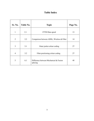
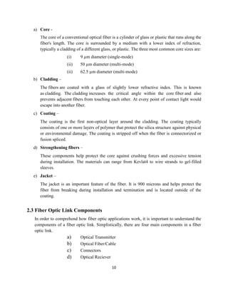
f) Figure 2.1 shows three curves. The top, dashed, curve corresponds to early 1980’s fiber,
the middle, dotted, curve corresponds to late 1980’s fiber, and the bottom, solid, curve
corresponds to modern optical fiber.
Fig. 2.1: Optical Loss Curve [1]](https://image.slidesharecdn.com/opticalfibercommunicationtrainingreport-161209092731/85/Optical-fiber-Communication-training-report-8-320.jpg)
![9
The earliest fiber optic systems were developed at an operating wavelength of about 850
nm. This wavelength corresponds to the so-called “first window” in a silica-based optical
fiber. This window refers to a wavelength region that offers low optical loss. It sits
between several large absorption peaks caused primarily by moisture in the fiber
and Rayleigh scattering.
g) Most companies jumped to the “second window” at 1310 nm with lower attenuation of
about 0.5 dB/km. In late 1977, Nippon Telegraph and Telephone (NTT) developed the
“third window” at 1550 nm. It offered the theoretical minimum optical loss for silica-
based fibers, about 0.2 dB/km.
h) Today, 850 nm, 1310 nm, and 1550 nm systems are all manufactured and deployed along
with very low-end, short distance, systems using visible wavelengths near 660 nm.
i) The shortest link lengths can be handled with wavelengths of 660 nm or 850 nm. The
longest link lengths require 1550 nm wavelength systems. A “fourth window,” near 1625
nm, is being developed. While it is not lower loss than the 1550 nm window, the loss is
comparable.
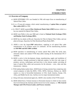
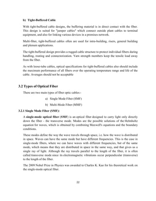
2.2 Elements of Optical Fiber
An optical fiber is a thin, flexible, transparent fiber that acts as a waveguide, or "light pipe",
to transmit light between the two ends of the fiber. Optical fibers are widely used in fiber-
optic communications, which permits transmission over longer distances and at higher
bandwidths (data rates) than other forms of communication. Fibers are used instead of metal
wires because signals travel along them with less loss and are also immune to
electromagnetic interference.
Fig. 2.2: Fiber cross-section [2]](https://image.slidesharecdn.com/opticalfibercommunicationtrainingreport-161209092731/85/Optical-fiber-Communication-training-report-9-320.jpg)
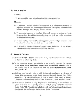
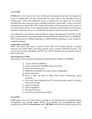
![11
Fig. 2.3: Optical link path [3]
a) Optical Transmitter-
The transmitter converts the electrical signals to optical. A transmitter contains a light
source such as a Light Emitting Diode (LED) or a Laser (Light Amplification by
Stimulated Emission of Radiation) diode, or a Vertical Cavity Surface Emitting Laser
(VCSEL).
(i) LED: Is used in multimode applications and has the largest spectral width that
carries the least amount of bandwidth.
Fig. 2.4: LED Beam [2]
(ii) VCSEL: Is also used in multimode applications with a narrower spectral width
that can carry more bandwidth than the LED.
Fig. 2.5: VCSEL Beam [3]](https://image.slidesharecdn.com/opticalfibercommunicationtrainingreport-161209092731/85/Optical-fiber-Communication-training-report-11-320.jpg)
![12
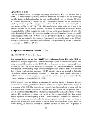
(iii) LASER: Has the smallest spectral width, carries the most bandwidth, and is used
in single mode applications.
Fig. 2.6: Laser Beam [2]
These sources produce light at certain wavelengths depending upon the materials
from which they are made. Most fiber optic sources use wavelengths in the infrared
band, specifically 850nm (1nm=10-9m), 1300nm and 1550nm. For reference, visible
light operates in the 400-700nm range (see Fig.2.7).
Fig. 2.7: Spectrum[2]
b) Optical Fiber/Cable-
In this section, we discuss the structure and properties of an optical fiber, how it guides
light, and how it is cabled for protection.
An optical fiber is made of 3 concentric layers (see Figure 2.8)](https://image.slidesharecdn.com/opticalfibercommunicationtrainingreport-161209092731/85/Optical-fiber-Communication-training-report-12-320.jpg)
![13
(i) Core: This central section, made of silica or doped silica, is the light transmitting
region of the fiber.
(ii) Cladding: This is the first layer around the core. It is also made of silica, but not
the same composition as the core. This creates an optical waveguide which
confines the light in the core by total internal reflection at the core-cladding
interface.
(iii) Coating: The coating is the first non-optical layer around the cladding. The
coating typically consists of one or more layers of polymer that protect the
silica structure against physical or environmental damage. The coating is
stripped off when the fiber is connectorized or fusion spliced.
Fig. 2.8: Fiber geometry [3]
(iv) Buffer (not pictured): The buffer is an important feature of the fiber. It is 900
microns and helps protect the fiber from breaking during installation and
termination and is located outside of the coating.
c) Connectors-
Fiber optic links require a method to connect the transmitter to the fiber optic cable and
the fiber optic cable to the receiver. In general, there are two methods to link optical
fibers together.
Fusion Splice: The first method is called a fusion splice. This operation consists of
directly linking two fibers by welding with an electric arc or a fusion splicer (see
Figure 2.9). The advantages of this approach are that the linking method is fast and
simple and there is very little insertion loss (the loss of light generated by a
connection is called Insertion Loss [IL]). The disadvantages are that the link is
relatively fragile, is permanent, and the initial cost (of the fusion splicer) is high.](https://image.slidesharecdn.com/opticalfibercommunicationtrainingreport-161209092731/85/Optical-fiber-Communication-training-report-13-320.jpg)
![14
Fig. 2.9: Splicer tool [3]
Connectors- The second method involves the uses of fiber optic connectors. A
connector terminates the optical fiber inside a ceramic ferrule, using epoxy to
hold the fiber in place. The connectors can be mated and unmated at any time.
The advantages of this approach are that the connection is robust, the connector
can be chosen according to the application, and the connector can be connected
and disconnected hundreds or even thousands of time without damaging the
connectors. The disadvantages of this approach are that the connectorization takes
longer than fusion splicing, requires special tools, and the insertion loss can be
higher when compared with fusion splicing.
There are two types of fiber optic connectors: physical contact and expanded
beam.
(i) Physical Contact Connectors- Physical contact connectors utilize fiber in
a tightly tolerance ceramic ferrule. This allows easy handling of the fiber
and protects it from damage. The principle of physical contact connectors
involves the direct contact of polished fibers within two ceramic ferrules.
The ferrules are aligned using a ceramic alignment sleeve (see Figure
2.10). Insertion loss is a function of the alignment accuracy and the polish
quality. There are springs behind the ferrule to ensure that the two ferrules
are in constant contact even in high vibration and shock environments.](https://image.slidesharecdn.com/opticalfibercommunicationtrainingreport-161209092731/85/Optical-fiber-Communication-training-report-14-320.jpg)
![15
Fig. 2.10: Contact connector [5]
(ii) Expanded Beam Technology- The other connector technology is
expanded beam, which consists of placing a lens at the exit of each fiber to
widen and collimate the light. In this configuration, there is an air gap
between the optical fibers/lens assemblies (see Figure 2.11). The loss
generated by an expanded beam connection is more than that of a physical
contact connector due to the lenses, mechanical alignment and sometimes
protective windows (approximately 0.8 to 2.5dB typical). This type of
connector performs well against particle contamination on the lens
because the beam is expanded to a much larger size than the beam that
comes directly from a fiber.
Fig. 2.11: Expanded beam [5]
d) Optical Receiver-
The last component of the fiber optic link is the optical receiver, which uses a photodiode
to convert the optical signals into electrical. The two types of photodiodes used are:
Positive Intrinsic Negative (PIN) and the Avalanche Photo Diode (APD).](https://image.slidesharecdn.com/opticalfibercommunicationtrainingreport-161209092731/85/Optical-fiber-Communication-training-report-15-320.jpg)
![16
2.4 How Optical Fiber Works
The operation of an optical fiber is based on the principle of total internal reflection (See fig.
2.12) Light reflects (bounces back) or refracts (alters its direction while penetrating a
different medium), depending on the angle at which it strikes a surface.
The angle of refraction at the interface between two media is governed by Snell’s law:
2211 sinsin nn
Fig. 2.12: Snell’s Law [3]
The light is "guided" down (see Figure 2.13) the core of the fiber by the optical "cladding"
which has a lower refractive index (the ratio of the velocity of light in a vacuum to its velocity
in a specified medium) that traps light in the core through "total internal reflection."
Fig. 2.13: TIR in Fiber [3]](https://image.slidesharecdn.com/opticalfibercommunicationtrainingreport-161209092731/85/Optical-fiber-Communication-training-report-16-320.jpg)
![17
2.5 Advantage of OFC
OFC has obvious advantages for the consumer, both today and in the foreseeable future,
offering improved performance for broadband services in comparison with those currently
delivered primarily over copper networks.
a) Speed: The speed comparison factor might be the most convincing one for you as
customers. OFC provides the highest possible speeds of Internet access downstream
(from the network to the end user) as well as upstream (from the user to the network).
Mobile connections are much slower than OFC, especially when several users are in the
same area and share the available network. Satellite connections are also much slower
than FTTH: they entail a delay, which hampers phone conversations and other
interactive activities. Other fixed technologies, like ADSL, use metal wires - which are
about 100 times slower than fibre to the home – to connect your home to the fiber city
network.
Keeping in mind that FTTH allows at least 1 Gbps download and 1 Gbps upload, the
following table drawn by the FTTH Council Europe shows typical download and upload
speeds for photo and video transfer for different bandwidth combination:
Table 2.1: FTTH Data speed [4]
Time taken for: 1 GB photo album 4.7 GB standard video 25 GB HD Video
1 Gbps download
1 Gbps upload
9 sec. 39 sec. 3 min 28 sec.
100 Mbps download
100 Mbps upload
1 min 23 sec. 6 min 31 sec. 34 in 40 sec.
50 Mbps download
10 Mbps upload
2 min 46 sec.
13 min 52 sec.
13 min 2 sec.
1 hr 5 min.
1 hr 9 min.
5 hr 47 min.
8 Mbps download
1 Mbps upload
19 min.
2 hr 32 min.
1 hr 29 min.
11 hr 54 min.
7 hr 55 min.
-
b) Reliability: Even though OFC speed is remarkable, we should consider other factors that
also impact on the end user service. Reliability is definitely one of these factors. An
FTTH broadband connection offers an improved network reliability.](https://image.slidesharecdn.com/opticalfibercommunicationtrainingreport-161209092731/85/Optical-fiber-Communication-training-report-17-320.jpg)
![18
c) Security: The reliability factor is linked with security. Magnetic fields don't just generate
noise in signal carrying conductors; they also make it possible to leak out the
information that is on the conductor. There are no radiated magnetic fields around
optical fibers; the electromagnetic fields are confined within the fiber. That makes it
impossible to tap the signal being transmitted through a fiber without cutting into the
fiber. Secure fiber networks can therefore help protect content from piracy when other
broadband solutions are more likely subject to these kinds of virtual threats or even
viruses.
Fiber offers many advantages when looking at the active network, as shown in the
following table (Table 2.2)
Table 2.2: Comparison between ADSL, Wireless & Fiber [4]
ADSL Wireless Fiber
Pros- Copper cables are
already there.
Pros- Ideal for non-reachable
places.
No cable needs to be
developed.
Pros- More Bandwidth
Reliability
Flexibility
High Security
Longer economic life
More types of services
possible with fiber
Cons- Loss in signal strength
Less secure
Low bandwidth
Cons- Less secure
Low bandwidth
Cons- Fibre optic cable are not
there yet, they need to be deployed.](https://image.slidesharecdn.com/opticalfibercommunicationtrainingreport-161209092731/85/Optical-fiber-Communication-training-report-18-320.jpg)

![20
CHAPTER 3
DESIGNING OF OPTICAL FIBER
3.1 Structure of Optical Fiber
The composition of the cladding glass relative to the core glass determines the fiber's
ability to reflect light. That reflection is usually caused by creating a higher refractive index
in the core of the glass than in the surrounding cladding glass. The refractive index of the
core is increased by slightly modifying the composition of the core glass, generally by
adding small amounts of a dopant. Figure. (3.1) is the graphical description of inside of
optical fiber. It shows that how light behave inside the fiber.
Fig. 3.1: Fiber structure [6]
The first step in manufacturing glass optical fibers is to make a solid glass rod, known as a
preform. Ultra-pure chemicals -- primarily silicon tetrachloride (SiCl4) and germanium
tetrachloride (GeCl4) -- are converted into glass during preform manufacturing.
These chemicals are used in varying proportions to fabricate the core regions for the
different types of preforms.
The basic chemical reaction of manufacturing optical glass is:](https://image.slidesharecdn.com/opticalfibercommunicationtrainingreport-161209092731/85/Optical-fiber-Communication-training-report-20-320.jpg)

![23
SMF has a very narrow core (typically around 9µm), which allows only single mode of light
to propagate.
Can support distances of up to several thousand kilometres, with appropriate amplification
and dispersion compensation.
Propagation of light rays can be easily understanding by the (Fig. 3.2).
Fig. 3.2: SMF [12]
It carries light pulses along single path. Only the lowest order mode (fundamental mode)
can propagate in the fiber and all higher modes are under cut-off condition.
It uses LASER as a light source. Single mode fibers are constructed by
a) Letting dimensions of core diameter be a few wavelengths
b) By having small index difference between core and cladding
In practice core-cladding index difference varies between 0.1 and 1.0 percent.
Typical single mode fibre may have a core radius of 3 microns an NA=0.1 at
wavelength= 0.8 micron.
3.2.2 Multi-Mode Fiber:
Multi-mode optical fiber is a type of optical fiber mostly used for communication over
short distances, such as within a building or on a campus. Typical multimode links have
data rates of 10 Mbit/s to 10 Gbit/s over link lengths of up to 600 meters (2000 feet).The
main difference between multi-mode and single-mode optical fiber is that the former has
much larger core diameter, typically 50–100 micrometres; much larger than the
wavelength of the light carried in it. Because of the large core and also the possibility of
large numerical aperture, multi-mode fiber has higher "light-gathering" capacity than
single-mode fiber. In practical terms, the larger core size simplifies connections and also
allows the use of lower-cost electronics such as light-emitting diodes (LEDs)
and vertical-cavity surface-emitting lasers (VCSELs) which operate at the 850 nm and
1300 nm wavelength (single-mode fibers used in telecommunications typically operate at](https://image.slidesharecdn.com/opticalfibercommunicationtrainingreport-161209092731/85/Optical-fiber-Communication-training-report-23-320.jpg)
![24
1310 or 1550 nm). However, compared to single-mode fibers, the multi-mode
fiber bandwidth–distance product limit is lower. Because multi-mode fiber has a larger
core-size than single-mode fiber, it supports more than one propagation mode; hence it is
limited by modal dispersion, while single mode is not.
The LED light sources sometimes used with multi-mode fiber produce a range of
wavelengths and these each propagate at different speeds. This chromatic dispersion is
another limit to the useful length for multi-mode fiber optic cable. In contrast, the lasers
used to drive single-mode fibers produce coherent light of a single wavelength. Due to
the modal dispersion, multi-mode fiber has higher pulse spreading rates than single mode
fiber, limiting multi-mode fiber’s information transmission capacity.
Single-mode fibers are often used in high-precision scientific research because restricting
the light to only one propagation mode allows it to be focused to an intense, diffraction-
limited spot.
Jacket colour is sometimes used to distinguish multi-mode cables from single-mode ones.
The standard TIA-598C recommends, for non-military applications, the use of a yellow
jacket for single-mode fiber, and orange or aqua for multi-mode fiber, depending on
type. Some vendors use violet to distinguish higher performance OM4 communications
fiber from other types.
Fig. 3.3: MMF [10]
3.2.3 Single Mode v/s Multi-Mode:
Now, we are studying the combine behaviour of single mode and multi-mode fiber with
respect to their efficiency and ways of propagation.](https://image.slidesharecdn.com/opticalfibercommunicationtrainingreport-161209092731/85/Optical-fiber-Communication-training-report-24-320.jpg)
![25
Fig. 3.4: Light ray in SMF & MMF [9]
Typical multimode fibers have a core diameter/cladding diameter ratio of 50 microns/125
microns (10-6 meters) and 62.5/125 (although 100/140 and other sizes are sometimes used
depending on the application). Single mode fibers have a core/cladding ratio of 9/125 at
wavelengths of 1300nm and 1550nm.It is shown in (fig. 3.5)
Fig. 3.5: Core Dimension [8]
Single Mode fiber optic cable has a small diametric core that allows only one mode of light
to propagate. Because of this, the number of light reflections created as the light passes
through the core decreases, lowering attenuation and creating the ability for the signal to](https://image.slidesharecdn.com/opticalfibercommunicationtrainingreport-161209092731/85/Optical-fiber-Communication-training-report-25-320.jpg)
![26
travel further. This application is typically used in long distance, higher bandwidth runs by
Telcos, CATV companies, and Colleges and Universities.
Single Mode fiber is usually 9/125 in construction. This means that the core to cladding
diameter ratio is 9 microns to 125 microns.
Fig. 3.6: Single mode [14]
Multimode fiber optic cable has a large diametric core that allows multiple modes of light to
propagate. Because of this, the number of light reflections created as the light passes through the
core increases, creating the ability for more data to pass through at a given time. Because of the
high dispersion and attenuation rate with this type of fiber, the quality of the signal is reduced
over long distances. This application is typically used for short distance, data and audio/video
applications in LANs. RF broadband signals, such as what cable companies commonly use,
cannot be transmitted over multimode fiber.
Multimode fiber is usually 50/125 and 62.5/125 in construction. This means that the core to
cladding diameter ratio is 50 microns to 125 microns and 62.5 microns to 125 microns.
Fig. 3.7: Multimode cross section [4]](https://image.slidesharecdn.com/opticalfibercommunicationtrainingreport-161209092731/85/Optical-fiber-Communication-training-report-26-320.jpg)
![27
3.2.4 What’s Happening Inside the Multimode Fiber-
Step-Index Multimode Fiber
Due to its large core, some of the light rays that make up the digital pulse may travel a direct
route, whereas others zigzag as they bounce off the cladding. These alternate paths cause the
different groups of light rays, referred to as modes, to arrive separately at the receiving point.
The pulse, an aggregate of different modes, begins to spread out, losing its well-defined shape.
The need to leave spacing between pulses to prevent overlapping limits the amount of
information that can be sent. This type of fiber is best suited for transmission over short
distances.
Graded-Index Multimode Fiber
Contains a core in which the refractive index diminishes gradually from the centre axis out
toward the cladding. The higher refractive index at the centre makes the light rays moving down
the axis advance more slowly than those near the cladding. Due to the graded index, light in the
core curves helically rather than zigzag off the cladding, reducing its travel distance. The
shortened path and the higher speed allow light at the periphery to arrive at a receiver at about
the same time as the slow but straight rays in the core axis. The result: digital pulse suffers less
dispersion. This type of fiber is best suited for local-area networks.
3.3 Types of Optical Fiber & Colour Coding
(a) Distribution Cable:
Fig. 3.8: Distributed [16]
Distribution Cable (compact building cable) packages individual 900µm buffered fiber
reducing size and cost when compared to breakout cable. The connectors may be installed
directly on the 900µm buffered fiber at the breakout box location. The space saving](https://image.slidesharecdn.com/opticalfibercommunicationtrainingreport-161209092731/85/Optical-fiber-Communication-training-report-27-320.jpg)
![28
(OFNR) rated cable may be installed where ever breakout cable is used. FIS will
connectorize directly onto 900µm fiber or will build up ends to a 3mm jacketed fiber
before the connectors are installed.
(b) Indoor/Outdoor Tight Buffer:
Fig. 3.9: Tight buffer [16]
FIS now offers indoor/outdoor rated tight buffer cables in Riser and Plenum rated
versions. These cables are flexible, easy to handle and simple to install. Since they do not
use gel, the connectors can be terminated directly onto the fiber without difficult to use
breakout kits. This provides an easy and overall less expensive installation. (Temperature
rating -40ºC to +85ºC).
(c) Indoor/Outdoor Breakout Cable:
Fig. 3.10: Indoor breakout cable [16]
FIS indoor/outdoor rated breakout style cables are easy to install and simple to terminate
without the need for fan-out kits. These rugged and durable cables are OFNR rated so
they can be used indoors, while also having a -40c to +85c operating temperature range
and the benefits of fungus, water and UV protection making them perfect for outdoor
applications. They come standard with 2.5mm sub units and they are available in plenum
rated versions.](https://image.slidesharecdn.com/opticalfibercommunicationtrainingreport-161209092731/85/Optical-fiber-Communication-training-report-28-320.jpg)
![29
(d) Loose Tube Cable:
Fig. 3.11: Losse Tube [16]
Loose tube cable is designed to endure outside temperatures and high moisture
conditions. The fibers are loosely packaged in gel filled buffer tubes to repel water.
Recommended for use between buildings that are unprotected from outside elements.
Loose tube cable is restricted from inside building use, typically allowing entry not to
exceed 50 feet
(e) Aerial Cable/Self-Supporting:
Fig. 3.12: Aerial Cable [16]
Aerial cable provides ease of installation and reduces time and cost. Figure 8 cable can
easily be separated between the fiber and the messenger. Temperature range ( -55ºC to
+85ºC).
(f) Hybrid & Composite Cable:
Fig. 3.13: Composite [16]](https://image.slidesharecdn.com/opticalfibercommunicationtrainingreport-161209092731/85/Optical-fiber-Communication-training-report-29-320.jpg)
![30
Hybrid cables offer the same great benefits as our standard indoor/outdoor cables, with
the convenience of installing multimode and single mode fibers all in one pull. Our
composite cables offer optical fiber along with solid 14 gauge wires suitable for a variety
of uses including power, grounding and other electronic controls.
(g) Armoured Cable:
Fig. 3.14: Armoured cable [16]
Armoured cable can be used for rodent protection in direct burial if required. This cable
is non-gel filled and can also be used in aerial applications. The armour can be removed
leaving the inner cable suitable for any indoor/outdoor use. (Temperature rating -40ºC to
+85ºC).
Colour Coding:
The type of fiber can be identified by use the of standardized colours on the outer jacket. As
shown in the given Table 3.1.
Table 3.: Outer jacket colour coding [18]
Colour Fiber Type
Orange 62.5µm (OM1) or 50µm (OM2) Multi-Mode Fiber
Yellow 8-10 µm Single-Mode Fiber
Aqua 10 Gbps + 50µm (OM3) Multi-Mode Fiber
Blue Polarization maintaining Single Mode Fiber](https://image.slidesharecdn.com/opticalfibercommunicationtrainingreport-161209092731/85/Optical-fiber-Communication-training-report-30-320.jpg)
![31
Now to define the position of further fiber hair, there is an another colour code for the
positioning of fiber. As shown in the table 3.2.
Table 3.2: Fiber positioning colour coding [18]
Position Number Colour Mode
1 Blue
2 Orange
3 Green
4 Brown
5 Slate
6 White
7 Red
8 Black
9 Yellow
10 Violet
11 Rose
12 Aqua
13 through 24 Repeat colours 1 through 12
with black tracer](https://image.slidesharecdn.com/opticalfibercommunicationtrainingreport-161209092731/85/Optical-fiber-Communication-training-report-31-320.jpg)
![32
CHAPTER 4
OPTICAL NETWORKS
4.1 Passive Optical Networks
Passive Optical Network (PON) is a telecommunications technology that implements a point-
to-multipoint architecture, in which unpowered fiber Optic Splitters are used to enable a
single optical fiber to serve multiple end-points such as customers, without having to provision
individual fibers between the hub and customer.
Fig. 4.1: PON Network [14]
A PON consists of an optical line terminal (OLT) at the service provider's central office (hub)
and a number of optical network units (ONUs) or Optical Network Terminals (ONTs), near end
users. A PON reduces the amount of fiber and central office equipment required compared
with point-to-point architectures. A passive optical network is a form of fiber-optic access
network. In most cases, downstream signals are broadcast to all premises sharing multiple
fibers. Encryption can prevent eavesdropping. Upstream signals are combined using a multiple
access protocol, usually time division multiple access (TDMA). PON can be divided into
following types –](https://image.slidesharecdn.com/opticalfibercommunicationtrainingreport-161209092731/85/Optical-fiber-Communication-training-report-32-320.jpg)
![34
a distance of 100 meters. Fiber is often said to be "future-proof" because the data rate of the
connection is usually limited by the terminal equipment rather than the fiber, permitting
substantial speed improvements by equipment upgrades before the fiber itself must be upgraded.
Still, the type and length of employed fibers chosen, e.g. multimode vs. single-mode, are critical
for applicability for future connections of over 1 Gbit/s.
4.1.3 FTTP:
FTTP (fiber-to-the-premises): This term is used either as a blanket term for both FTTH and
FTTB, or where the fiber network includes both homes and small businesses. Fiber to the
premises (FTTP) is a form of fiber-optic communication delivery, in which an optical fiber is run
in an optical distribution network from the central office all the way to the premises occupied by
the subscriber. The term "FTTP" has become ambiguous and may also refer to FTTC where the
fiber terminates at a utility pole without reaching the premises.
4.1.4 FTTDp:
Fiber to the Distribution Point (FTTDp)–this solution has been proposed in the last two years.
Connecting the POP to the Distribution Point via the optical cable and then from the Distribution
Point to the end-user premises via existing copper infrastructure. The Distribution Points could
be a hand-hole, a drop box on the pole or located in the basement of a building. This architecture
could support VDSL or G. Fast technology for a short last mile, normally less than 250m.
Fig. 4.2: FTTx Comparison [12]](https://image.slidesharecdn.com/opticalfibercommunicationtrainingreport-161209092731/85/Optical-fiber-Communication-training-report-34-320.jpg)
![36
made more complex by the decision to permit this padding at most levels of the multiplexing
structure, but it improves all-around performance.
Fig. 4.3: Sonet Ring [15]
4.2.2 SONET Multiplexing:
The multiplexing principles of SONET are as follows-
Mapping: It is used when tributaries are adapted into VTs by adding justification bits and POH
information.
Aligning: It takes place when a pointer is included in STS path or VT POH, to allow the first
byte of VT to be located.
Multiplexing: Used when multiple order lower path-layer signals are adapted into a higher
order- path signal or vice-versa.
Stuffing: SONET has ability to handle various input tributary rates from asynchronous signals;
as the tributary signals are multiplexed and aligned, some spare capacity has been designed into
the SONET frame to provide enough space for all these various tributary rates; therefore, at
certain point in multiplexing hierarchy, this space capacity is filled with fixed stuffing bits that
carry no information but are required to fill up the particular frame.
One of the benefits of SONET is that it can carry large payloads (50 Mbps). However, the
existing digital hierarchy signals can be accommodated as well, thus protecting investment in
current equipment.
Figure 4.4 illustrates the basic multiplexing structure of SONET. Any type of services, ranging
from voice to high-speed data and video, can be accepted by various types of service adapters.](https://image.slidesharecdn.com/opticalfibercommunicationtrainingreport-161209092731/85/Optical-fiber-Communication-training-report-36-320.jpg)
![37
Fig. 4.4: Sonet Multiplexing Hierarchy [7]
4.2.3 Benefits of SONET:
Today's carrier backbone networks are supported by synchronous optical network (SONET)
and synchronous digital hierarchy (SDH) transmission technologies. SONET is the standard
used in the United States and SDH is the standard used outside the United States.
SONET/SDH specification outlines the frame format, multiplexing method, and
synchronization method between the equipment, as well as the specifying optical interface.
SONET/SDH will continue to play a key role in the next generation of networks for many
carriers. In the core network, the carriers offer services such as telephone, dedicated leased
lines, and Internet protocol (IP) data, which are continuously transmitted. The individual data
is not transmitted on separate lines; instead it is multiplexed into higher speeds and
transmitted on SONET/SDH networks at up to 10 gigabits per second (Gbps). The following
sections describe the need for SONET/SDH.
Synchronous Digital Transmission
Until the introduction of SONET in the mid-1980s, plesiochronous digital hierarchy (PDH)
systems commonly used data multiplexing technology. The primary problem with PDH was
that to extract low-speed traffic, all traffic that was multiplexed to higher speeds had to be de-
multiplexed into lower speeds. With PDH, the equipment had to support multiplexing and de-
multiplexing the signal, adding cost and complexity to the network. SONET was introduced
as a synchronous transmission system that could directly extract low-speed signals from
multiplexed high-speed traffic. Based on the ANSI standard, the CCITT approved the
international standard known as SDH based on the SONET technology.](https://image.slidesharecdn.com/opticalfibercommunicationtrainingreport-161209092731/85/Optical-fiber-Communication-training-report-37-320.jpg)
![38
Mid-Span Meet
The adoption and acceptance of SONET allowed carriers to be able to choose equipment from
different vendors instead of using only a single vendor with a proprietary optical format. The
ability to mix equipment from different vendors in one system is called the "Mid-Span Meet".
Speed
SONET and SDH give carriers much more bandwidth to carry voice and data traffic than
PDH technology. The base rate for SONET is 51 Mbps. Synchronous transport signal (STS-n)
refers to the SONET signal in the electrical domain, and optical carrier (OC-n) refers to the
SONET signal in the optical domain. The base rate for SDH is 155 Mbps. Synchronous
transport module (STM-n) refers to the SDH signal level in both the electrical and optical
domains.
Reliability
Carriers require an extremely reliable network and cannot afford downtime. Therefore, most
SONET/SDH networks have a ring structure, which adds high reliability to the overall
transmission network. Even if the optical fiber is cut, the transmission path is backed-up and
restored within 50 ms. Figure 4.5 shows an example SONET ring.
Fig. 4.5: Sonet Ring [10]
A SONET/SDH transmission network is composed of several pieces of equipment, including:
(a) Terminal multiplexer (TM)
(b) Add-drop multiplexer (ADM)
(c) Repeater
(d) Digital cross-connect system (DCS)](https://image.slidesharecdn.com/opticalfibercommunicationtrainingreport-161209092731/85/Optical-fiber-Communication-training-report-38-320.jpg)
![39
Chapter 5
OPTICAL FIBER INSTALLATION
5.1 Introduction:
Fiber optic network installation refers to the specialized processes leading to a successful
installation and operation of a fiber optic network. It includes determining the type of
communication system(s) which will be carried over the network, the geographic layout
(premises, campus, outside plant (OSP, etc.), the transmission equipment required and the fiber
network over which it will operate. Next we have to consider requirements for permits,
easements, permissions and inspections. Once we get to that stage, we can consider actual
component selection, placement, installation practices, testing, troubleshooting and network
equipment installation and start-up. Finally, we have to consider documentation, maintenance
and planning for restoration in event of an outage.
5.2 Surveying & Preparing area root map:
It is the first and most significant step of optical fiber installation. Here, first a survey team is
sent to the targeted area, where they do a survey on number of customers interested and how the
fibre will be laid. The task of the optical engineer is to draw a root map according to the
requirement, in such way that minimum of resources used. Then the engineer makes a rough
sketch of fibre laying root, and then sent it to service division for other formalities.
Fig. 5.1: Google street view [18]](https://image.slidesharecdn.com/opticalfibercommunicationtrainingreport-161209092731/85/Optical-fiber-Communication-training-report-39-320.jpg)
![40
Whether a network is planned for an area with a high or a low population density the approach
will be a completely different exercise as the optimal architecture and design rules for these
networks will differ greatly:
• In a dense area, one provider will choose to group more subscribers on a single aggregation
point and achieve a relatively good filling of all aggregation points; however in rural areas
distance between buildings and aggregation points may become a more important constraint in
the design than capacity of each aggregation point, resulting in a broader variation in filling of
aggregation points.
• In dense areas there are, in general, more equivalent options for grouping buildings around
aggregation points, as well as for routing the cables between aggregation points and buildings. In
rural areas there are less equivalent alternatives.
• Rural areas will have more options for placing cabinets, while urban areas spaces are limited
and thus more constraints apply for cabinet placement.
• Unit costs for deploying cables can differ significantly between urban and rural areas: in rural
areas, one meter of trenching will be less expensive than similar trenching in urban areas, as, for
example, the type of pavement in the two areas differs as does the associated cost of restoring the
individual pavements. Additionally, more aerial deployments are used in rural areas. This will
impact on the relationship between labour and material costs of both types of deployment, thus
requiring a different set of design rules to be used for achieving minimal costs
• Equipment vendors have developed special deployment methods and cable types for urban
versus rural deployments.
Regarding route information, a minimal input is the street topology information. This data is
available for most areas. Typical data providers for street topologies are the providers of large
geographical information systems (GIS) databases that are also used for car navigation systems.
This data is often displayed on mapping and route planning websites such as
http://maps.google.com. Alternative local data providers may exist. For some regions, the open
source data from OpenStreetMap, www.openstreetmap.org may be a good starting point.
Fig. 5.2: Satellite view [18]](https://image.slidesharecdn.com/opticalfibercommunicationtrainingreport-161209092731/85/Optical-fiber-Communication-training-report-40-320.jpg)
![41
5.3 Trenching:
A trench is a type of excavation or depression in the ground that is generally deeper than it is
wide (as opposed to a wider gully, or ditch), and narrow compared to its length.
The advantages of this technique over conventional cable laying technologies lie essentially
in its speed of execution, lower cost, significantly lower environmental impact and limited
disruption to road traffic and, as a consequence of the previous items, easiness in obtaining
permits for the taking over of public area.
Trenching can be carried out by two methods either by labour workers as per the route plan
requirements and site terrain or by a machine known as trencher. A trencher is a piece
of construction equipment used to dig trenches, especially for laying pipes or cables, for
installing drainage, or in preparation for trench warfare. Trenchers may range in size from
walk-behind models, to attachments for a skid loader or tractor, to very heavy tracked heavy
equipment.
Fig. 5.3: Fiber Laying [19]
After trenching, the next step is laying of duct in trench. Duct is that pipe in which fibre cables
are going to blow. They are made up of hard plastic. The another method of laying duct is
through HDD.
HDD: HDD stands for Horizontal Directional Drilling; it is used to lay duct without trenching
the ground. It has a flexible drilling bid which drills underground up to 1-3 Km. It is a steerable
trenchless method of installing underground pipe, conduit, or cable in a shallow arc along a
prescribed bore path by using a surface-launched drilling rig, with minimal impact on the
surrounding area.](https://image.slidesharecdn.com/opticalfibercommunicationtrainingreport-161209092731/85/Optical-fiber-Communication-training-report-41-320.jpg)
![42
Fig. 5.4: HDD working [17]
5.4 Cable Jetting:
Cable Pulling is the traditional method of pulling cables through previously installed cable ducts
or conduit using a pull line. Successful pulling requires cables to be pulled at the straightest
angles possible. The fewer bends that the cable needs to be pulled through — the better. A
generous amount of Cable Pulling Lubricant should also be used during the entire process to
decrease friction and avoid damaging the cable. Clear communication between installation team
members is also essential when pulling cable. The technique of installing flexible and
lightweight fibre optic units using compressed air was developed during the 1980s by British
Telecom. This early version of jetting did not use additional pushing. True cable jetting was
invented by Willem Griffioen of KPN Research in the late 1980s. Cable jetting is the process of
blowing a cable through a duct while simultaneously pushing the cable into the duct.
Compressed air is injected at the duct inlet and flows through the duct and along the cable at high
speed.
Cable jetting is the process of blowing a cable through a duct while simultaneously pushing the
cable into the duct. Compressed air is injected at the duct inlet and flows through the duct and
along the cable at high speed. (Preferably, no suction pig is used at the cable head.) The high
speed air propels the cable due to drag forces and pressure drop. The friction of the cable against
the duct is reduced by the distributed airflow, and large forces that would generate high friction
are avoided. Because of the expanding airflow, the air propelling forces are relatively small at
the cable inlet and large at the air exhaust end of the duct. To compensate for this, an additional
pushing force is applied to the cable by the jetting equipment. The pushing force, acting mainly
near the cable inlet, combined with the airflow propelling forces, increases the maximum jetting
distance considerably. Special lubricants have been developed for cable jetting to further reduce
friction.](https://image.slidesharecdn.com/opticalfibercommunicationtrainingreport-161209092731/85/Optical-fiber-Communication-training-report-42-320.jpg)
![43
Fig. 5.5: Cable jetting techniques [17]
The advantages of cable jetting over cable pulling include:
(a) Longer installation distances possible
(b) Bends in duct don’t hinder jetting process
(c) Less force is exerted on the cable
(d) No need to install a winch rope
(e) Equipment only needed at one end of route](https://image.slidesharecdn.com/opticalfibercommunicationtrainingreport-161209092731/85/Optical-fiber-Communication-training-report-43-320.jpg)
![45
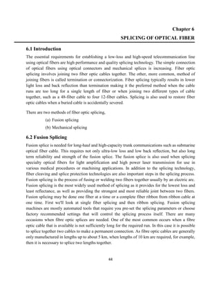
The major steps involved in optical fiber fusion splicing can be summarized as the following.
a) Optical fiber stripping: The fiber cable jacket is removed and then the fiber polymer coating
is stripped with fiber optic strippers.
b) Fiber cleaving: The fiber is cleaved with specialized tool called fiber cleaver. Two types of
fiber cleaver exist: high precision fiber cleaver for single mode applications and field cleaver for
multimode applications. A mirror like almost perfect end face is achieved by this cleaving
process.
c) Fiber alignment: The fibers are laterally aligned to each other by step motor in a fusion
splicer. This may involve rotating the fibers in polarization maintaining fiber splicing.
d) Fiber welding: The fibers are then heated with electric arc or other methods to the fiber
glass's softening point and then both fibers are pressed together to form a solid joint.
e) Insertion loss estimation: The insertion loss is estimated based on the fusion quality and
dimensions.
f) Pull tension strength testing: The fusion is pull proof tested when opening the fusion splicer
cover.
g) Splice protection with fusion splice sleeve: The fusion splice joint is then protected with a
heat shrink tube with a steel strength member inside to form a solid and reliable fiber joint.
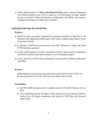
Fig. 6.1: Fusion electric arc [9]](https://image.slidesharecdn.com/opticalfibercommunicationtrainingreport-161209092731/85/Optical-fiber-Communication-training-report-45-320.jpg)
![46
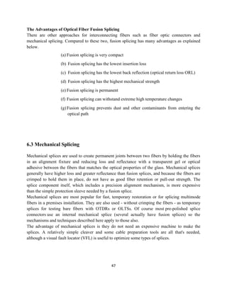
Fig. 6.2: Optical cleaver [9] Fig. 6.3: Strippers [6]
Optical fiber applications have expanded to many fields other than telecommunications. We
developed a specialty fiber fusion splicer that has an adjustable fiber clamping position
mechanism, electrode oscillating mechanism, and optical fiber end-view image observation
system in order to splice various types, such as polarization maintaining fibers and large
diameter fibers for high power laser transmission. Fig.6.4 shows the appearance of this splicer.
Fig. 6.4: Fusion splice [20]](https://image.slidesharecdn.com/opticalfibercommunicationtrainingreport-161209092731/85/Optical-fiber-Communication-training-report-46-320.jpg)
![48
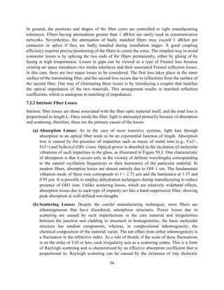
Fig. 6.5: Mechanical splice equipment [23]
What Is Mechanical Fiber Splice?
Fiber optic mechanical splice performs a similar function to the fusion splice except that the
fibers are held together by mechanical means rather than by a welding technique. Mechanical
splices somewhat look like fusion splice protection sleeves. In a mechanical splice, two cleaved
fiber tips are mechanically aligned to each other by a special housing. Usually, index matching
gel is positioned between the fiber tips to maximize coupling and minimize back reflection.
Advantages of Mechanical Splice
There are some significant advantages of using mechanical fiber splice than fusion splices. Here
are a few of them:
(a) Mechanical splices require no power supplies
(b) Many mechanical fiber splice designs require no extra tools beyond a fiber stripper and
fiber cleaver
(c) They can be used in situations where fusion splicing is not practical or impossible
(d) Mechanical splices can be made within a couple of minutes, this makes it ideal for
temporary connections
Disadvantages of Mechanical Fiber Splices
Fiber optic mechanical splices have their cons too.
(a) Higher insertion loss. The typical insertion loss for a mechanical splice is about 0.2dB
which is significantly higher than the 0.02dB loss for a typical fusion splice.](https://image.slidesharecdn.com/opticalfibercommunicationtrainingreport-161209092731/85/Optical-fiber-Communication-training-report-48-320.jpg)
![49
(b) Mechanical splices are typically for multimode fibers. The tough alignment tolerance for
single mode fibers makes it hard for mechanical splices to meet
(c) Mechanical splice is more expensive than fusion splices. But if you take into account the
expensive fusion splicing machines that fusion splices need, the average cost is actually
much lower for mechanical splice if you just do a few splices.
(d) Since the refractive index of most index matching compounds varies with temperature, so
the optical performance of a mechanical splice can be sensitive to ambient temperature
(e) Mechanical splices are not thought to be as reliable as fusion splices over long periods of
time
(f) Mechanical splices are used only in relatively benign environments such as inside an
office building.
Alignment Mechanisms of Mechanical Fiber Optic Splices
The principle of mechanical splice is simple and straightforward. Two fibers are stripped,
cleaned and cleaved. They are then aligned and held in position either by epoxy resin or by
mechanical clips.
1. V-Groove Type
V-groove has been used widely in aligning optical fibers. The most obvious example is
its success in fusion splicing machines. Look at the following illustration (Fig. 6.6).
Fig. 6.6: V-Groove picture [14]](https://image.slidesharecdn.com/opticalfibercommunicationtrainingreport-161209092731/85/Optical-fiber-Communication-training-report-49-320.jpg)
![50
V-groove is the most commonly used alignment mechanism for mechanical fiber splices.
V-groove consists of a base plate in which a precise V-groove is etched.
(a) Cleaved fibers are placed into the groove and their ends are butt-coupled into
contact.
(b) Index matching gel is used to bridge the gap between the two ends to prevent gap
loss and to reduce Fresnel reflection
(c) A locking mechanism then holds the fibers in position and provides mechanical
protection for the fibers
(d) Index matching epoxy can be used in place of index matching gel. The epoxy is
usually cured with ultraviolet light. The epoxy can hold the fibers in place
2. Bent Tube Type
Bent tube design actually uses the same principle as V-groove. A length of fiber is pushed into
a tube which is curved, the springiness of the fiber forces itself to follow the outside of the
curve. If the tube is of square cross-section, the fiber will follow the far corner. The fiber is
now positioned by a V-shaped wall of the tube. In some designs, the cross-section of the bent
tube is circular instead of square. Index matching gel is added before the fibers are inserted.
Fig. 6.6: Bent tube [20]](https://image.slidesharecdn.com/opticalfibercommunicationtrainingreport-161209092731/85/Optical-fiber-Communication-training-report-50-320.jpg)
![51
3. Precision Tube Type
The precision tube type is very simple and straightforward. A precise hole with a slightly
larger diameter than the fiber OD is formed through a piece of ceramic or other material.
When a piece of bare fiber is inserted from each end, the two fibers are aligned when they
contact.
The disadvantage of this type is that insertion loss is higher than other types. This is caused by
the hard to control tolerance of the hole diameter.
6.4 Fusion v/s Mechanical Splicing:
Mechanical and fusion splicing both accomplish the same thing; they bring two optical
fibres together and hold them that way so that an optical signal can pass through the join.
However, this is where the similarities end--and, for contractors, where weighing trade-offs
begins. Overall, the advantages of fusion splicing are primarily lower loss and better
reflectance performance; it is in these areas that it surpasses mechanical splicing.
In the early days of fiber optics, fusion splicing was an exacting, demanding task. Today -
although care is needed - the splicing procedure is straightforward, with key steps fully
automated. Mechanical and fusion splicing are two broad categories that describe the
techniques used for fiber splicing. A Mechanical Splice is a fiber splice where mechanical
fixtures and materials perform fiber alignment and connection. A fusion splice is a process
of using localized heat to melt or fuse the ends of two optical fibers together. Each splicing
technique seeks to optimize splice performance and reduce splice loss. Low-loss fiber
splicing results from proper fiber end preparation and alignment. Mechanical splices have
higher insertion losses, lower reliability and higher return losses than fusion splicing.
Table 6.1: Comparison between fusion & mechanical splicing [16]
Sr. No. Fusion Splicing Mechanical Splicing
1. Two fibre end are aligned and then
fused together.
Just a mechanical alignment device.
2. Fused with the help of electric arc. Splice with the help of index
matching gel.
3. Still, two separated fibres are not
continuous.
The joint is continuous.
5. Due to electric arc, the strength of
glass core is weaken at the point of
splicing, which cause losses.
No such problem is encountered in
mechanical splicing.](https://image.slidesharecdn.com/opticalfibercommunicationtrainingreport-161209092731/85/Optical-fiber-Communication-training-report-51-320.jpg)

![53
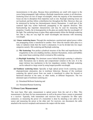
Fig. 7.1: Bending loss [5]
(b) Launching Losses: The term launching loss refers to an optical fiber not being able to
propagate all the incoming light rays from an optical source. These occur during the
process of coupling light into the fiber (e.g., losses at the interface stages). Rays launched
outside the angle of acceptance excite only dissipative radiation modes in the fiber. In
general, elaborate techniques have been developed to realize efficient coupling between
the light source and the fiber, mainly achieved by means of condensers and focusing
lenses. The focused input beam of light needs to be carefully matched by fiber parameters
for good coupling. Equally, once the light is transmitted through the fiber, output fiber
characteristics must also match the output target characteristics to be able to couple the
largest proportion of the transmitted light. This can be done by a suitable focusing lens
arrangements in the output end.
(c) Connector Losses: Connector losses are associated with the coupling of the output of
one fiber with the input of another fiber, or couplings with detectors or other components.
The significant losses may arise in fiber connectors and splices of the cores of the joined
fibers having unequal diameters or misaligned centres, or if their axes are tilted.
Fig. 7.2: Connector Loss [24]](https://image.slidesharecdn.com/opticalfibercommunicationtrainingreport-161209092731/85/Optical-fiber-Communication-training-report-53-320.jpg)
![56
Fig. 7.3: Power Measurement [22]
While optical power meters are the primary power measurement instrument, optical time
domain reflectometers (OTDRs) also measure power in testing loss.
Optical power is based on the heating power of the light, and some optical lab instruments
actually measure the heat when light is absorbed in a detector. While this may work for high
power lasers, these detectors are not sensitive enough for the low power levels typical for
fiber optic communication systems.
7.3.1 Power Meter:
An optical power meter (OPM) is a device used to measure the power in an optical signal.
The term usually refers to a device for testing average power in fiber optic systems. Other
general purpose light power measuring devices are usually
called radiometers, photometers, laser power meters (can be photodiode sensors
or thermopile laser sensors), light meters or lux meters. A typical optical power meter
consists of a calibrated sensor, measuring amplifier and display. The sensor primarily
consists of a photodiode selected for the appropriate range of wavelengths and power levels.
On the display unit, the measured optical power and set wavelength is displayed. Power
meters are calibrated using a traceable calibration standard such as a NIST standard. A
traditional optical power meter responds to a broad spectrum of light, however the calibration
is wavelength dependent. This is not normally an issue, since the test wavelength is usually
known, however it has a couple of drawbacks. The most basic fiber optic measurement is
optical power from the end of a fiber. This measurement is the basis for loss measurements
as well as the power from a source or presented at a receiver.](https://image.slidesharecdn.com/opticalfibercommunicationtrainingreport-161209092731/85/Optical-fiber-Communication-training-report-56-320.jpg)
![57
Measurement of the power of a transmitter is done by attaching a test cable to the source and
measuring the power at the other end. For receivers, one disconnects the cable attached to the
receiver receptacle and measures the output with the meter. Optical power meters typically
use semiconductor detectors since they are sensitive to light in the wavelengths and power
levels common to fiber optics. Most fiber optic power meters are available with a choice of 3
different detectors, silicon (Si), Germanium (Ge), or Indium-Gallium-Arsenide (In GaAs).
Fig. 7.4: Power Meter [16]
7.3.2 OTDR:
The OTDR is the most important investigation tool for optical fibres, which is applicable for
the measurement of fibre loss, connector loss and for the determination of the exact place and
the value of cable discontinuities. By means of very short pulses it is also possible to
measure the modal dispersion of multimodal fibres. The structure of a typical OTDR
equipment is shown below:](https://image.slidesharecdn.com/opticalfibercommunicationtrainingreport-161209092731/85/Optical-fiber-Communication-training-report-57-320.jpg)
![58
Fig. 7.5: OTDR [16]
The principal of the OTDR analyser is the following: a short light pulse is transmitted into
the fibre under test and the time of the incidence and the amplitude of the reflected pulses are
measured. The commonly used pulse width ranges from nanosecs to microsecs, the power of
the pulse can exceed 10 mW. The repetition frequency depends on the fibre length, typically
is between 1 and 20 kHz, naturally it is smaller for longer fibres. The division by 2 at the
inputs of oscilloscope is needed since both the vertical (loss) and the horizontal (length)
scales correspond to the one-way length.
Some of the terms often used in specifying the quality of an OTDR are as follows:
Accuracy: Defined as the correctness of the measurement i.e., the difference between the
measured value and the true value of the event being measured.
Measurement range: Defined as the maximum attenuation that can be placed between
the instrument and the event being measured, for which the instrument will still be able to
measure the event within acceptable accuracy limits.
Instrument resolution: Is a measure of how close two events can be spaced and still be
recognized as two separate events. The duration of the measurement pulse and the data
sampling interval create a resolution limitation for OTDRs. The shorter the pulse duration
and the shorter the data sampling interval, the better the instrument resolution, but the
shorter the measurement range. Resolution is also often limited when powerful
reflections return to the OTDR and temporarily overload the detector. When this occurs,
sometime is required before the instrument can resolve a second fiber event. Some OTDR
manufacturers use a “masking” procedure to improve resolution. The procedure shields
or “masks” the detector from high-power fiber reflections, preventing detector overload
and eliminating the need for detector recovery.](https://image.slidesharecdn.com/opticalfibercommunicationtrainingreport-161209092731/85/Optical-fiber-Communication-training-report-58-320.jpg)
![60
CHAPTER 9
REFERENCES
[1] Ming-Jun Li, Xin Chen, Daniel A. Nolan, Ji Wang, James A. West, and Karl W. Koch,
“Specialty fibers for optical communication systems” Optical Fiber Telecommunications V A:
Components and Subsystems, 2008, Elsevier.
[2] C. E. Shannon, “A mathematical theory of communication,” Bell Syst. Tech. J., vol. 27, pp.
379–423, 623–656, 1948.
[3] Jian Chao Li & Dennis R. Alexander, “Propagation of ultra-short laser pulses through
Water,” Optics Express, Vol. 15(4), pp.1939- 1946, February 2007.
[4] M. Noshada, A. Rostami, “FWM minimization in WDM optical communication systems
using the asymmetrical dispersion managed fibers” Optik 123 (2012) 758– 760
[5] X. Wang and K. Kitayama, "Analysis of beat noise in coherent and incoherent time-preading
OCDMA," J. Lightwave Technol 22, 2226-2235, (2004).
[6] T. H. Shake, "Confident performance of -encoded optical CDMA", J. Lightwave Technol.23,
1652- 1663, (2005).
[7] Antonio Mendez Senior Member, IEEE, Robert M. Gagliardi, Fellow, IEEE, Vincent
J.Hernandez J."Design and performance analysis of Wavelength/Time (WIT) matrix codes for
optical CDMA". Journal of light wave technology Vol.2lNovember 2003.
[8] M. Noshada, A. Rostami, “FWM minimization in WDM optical communication systems
using the asymmetrical dispersion managed fibers”, International Journal for Light and Electron
Optics, vol. 123, no. 9, pp. 758– 760, 2012.
[9] X. Wang and K. Kitayama, "Analysis of beat noise in coherent and incoherent time-spreading
OCDMA," IEEE/OSA Journal of Lightwave Technology, vol. 22, no. 10, pp. 2226-2235, 2004.
[10] T. H. Shake, "Confident performance of encoded optical CDMA", IEEE/OSA Journal of
Lightwave Technology, vol. 23, pp. 1652- 1663, 2005.
[11] Prachi Sharma et al, “A Review of the Development in the Field of Fiber Optic
Communication Systems”, International Journal of Emerging Technology and Advanced
Engineering, Vol. 3, no. 5, pp. 113-119, 2013.
[12] G. Keiser, op cit, p 51
[13] Franz Fidler, Markus Knapek, Joachim Horwath, and Walter R.Leeb, “Optical
Communications for High-Altitude Platforms”, IEEE Journal of Selected Topics in Quantum
Electronics, Vol. 16, no. 5, September/October 2010.](https://image.slidesharecdn.com/opticalfibercommunicationtrainingreport-161209092731/85/Optical-fiber-Communication-training-report-60-320.jpg)
![61
[14] T. Otani, K. Goto, H. Abe, M. Tanaka, H. Yamamoto, and H. Wakabayashi, Electron.
Lett.31, 380, 1995.
[15] Mizushima et al., “Improving Performance and Tolerance in Harsh Environmental
Conditions of New Fusion Splicer”, Fujikura Technical Review, Vol114, pp.17-20, 2008
[16] Iwashita et al., “Small Fusion Splicer Splice MateTM”, Fujikura Technical Review, Voll08,
pp.10-13, 2005.
[17] Tobita et al., “Specialty Fiber Fusion Splicer”, Fujikura Technical Review, Vol119, pp.17-
21, 2010
[18] Konuma et al., “Fusion Splicer for Specialty Optical Fiber with Advanced Functions”,
Fujikura Technical Review, Vol120, pp.12-15, 2011
[19] Iwashita et al., “Small Fusion Splicer and Fiber Cleaver”, Fujikura Technical Review,
Vol.35, pp.10-14, 2006
[20] http://www.thefoa.org/tech/ref/termination/mechsplice.html
[21] http://www.timbercon.com/medical-fiber-optics/
[22] http://www.fibersystems.com/products/navy/
[23] http://www.ratioplast.com/pdf/rpo/909/E09PM00000111_RevA01.pdf
[24] http://www.akshoptifibre.com/infrastructure.php](https://image.slidesharecdn.com/opticalfibercommunicationtrainingreport-161209092731/85/Optical-fiber-Communication-training-report-61-320.jpg)


