This document describes the data processing flow in oblu. It also describes communication protocol using which one can access & control the data, set internal parameters and the processing at various stages, through an external
application platform.
---
Oblu is an opensource development board for wearable motion sensing. It is also an Arduino compatible programmable IMU for diverse inertial sensing applications. It comes pre-programmed as a shoe-mounted pedestrian dead reckoning PDR sensor for indoor navigation and personnel tracking. Real time tracking of first responders, robot navigation, geo-survey, understanding physics of motion, activity monitoring of elderly, gaming, VR etc are only few from the long list of applications which have been demonstrated using oblu.
Oblu is battery operable and uses Bluetooth Low Energy BLE for wireless data transmission. It is easily configurable and comes along with an Android application Xoblu for personnel tracking, a PC-based tool MIMUscope for detailed analysis and hardware accessories for ease of usage. It is based on opensource OpenShoe platform. Since beginning, Oblu has been distributed in 22 countries, to students, DIY enthusiasts, industrial & academic researchers, entrepreneurs etc. Oblu comes from the makers of Inertial Elements which is a famous for making multi-IMU array modules available commercially.
Evolution of a shoe-mounted multi-IMU pedestrian dead reckoning PDR sensoroblu.io
Shoe-mounted inertial navigation systems, aka pedestrian dead reckoning or PDR sensors, are being preferred for pedestrian navigation because of the accuracy offered by them. Such shoe sensors are, for example, the obvious choice for real time location systems of first responders. The opensource platform OpenShoe has reported application of multiple IMUs in shoe-mounted PDR sensors to enhance noise performance. In this paper, we present an experimental study of the noise performance and the operating clocks based power consumption of multi-IMU platforms. The noise performances of a multi-IMU system with different combinations of IMUs are studied. It is observed that four-IMU system is best optimized for cost, area and power. Experiments with varying operating clocks frequency are performed on an in-house four-IMU shoe-mounted inertial navigation module (the Oblu module). Based on the outcome, power-optimized operating clock frequencies are obtained. Thus the overall study suggests that by selecting a well-designed operating point, a multi-IMU system can be made cost, size and power efficient without practically affecting its superior positioning performance.
Massive Sensors Array for Precision Sensingoblu.io
More than a billion smartphones being sold annually and growing with CAGR of 16%, the smartphone industry has become a driving force in the development of ultralow-cost inertial sensors. Unfortunately, these ultra low-cost sensors do not yet meet the needs of more demanding applications like inertial navigation and biomedical motion tracking systems. However, by adapting a wisdom of the crowd’s thinking and design arrays consisting of hundreds of sensing elements, one can capitalize on the decreasing cost, size, and power-consumption of the sensors to construct virtual high-performance low-cost inertial sensors. Team at KTH, Sweden and WUSTL, USA share findings and challenges.
Despite being around for almost two decades, footmounted inertial navigation only has gotten a limited spread. Contributing factors to this are lack of suitable hardware platforms and difficult system integration. As a solution to this, we present an open-source wireless foot-mounted inertial navigation module with an intuitive and significantly simplified dead reckoning interface. The interface is motivated from statistical properties of the underlying aided inertial navigation and argued to give negligible information loss. The module consists of both a hardware platform and embedded software. Details of the platform and the software are described, and a summarizing description of how to reproduce the module are given. System integration of the module is outlined and finally, we provide a basic performance assessment of the module. In summary, the module provides a modularization of the foot-mounted inertial navigation and makes the technology significantly easier to use.
An Experimental Study on a Pedestrian Tracking Deviceoblu.io
The implemented navigational algorithm of an inertial
navigation system (INS), along with the hardware configuration, decides its tracking performance. Besides, operating conditions also influence its tracking performance. The aim of this study is to demonstrate robust performance of a multiple Inertial Measurement Units (IMUs) based foot-mounted INS, The Osmium MIMU22BTP, under varying operating conditions. The device, which performs zero-velocity-update (ZUPT) aided navigation, is subjected to different conditions which could potentially influence gait of its wearer, its hardware configuration etc. The gait-influencing factors chosen for study are shoe type, walking surface, path profile and walking speed. Besides, the tracking performance of the device is also studied for different number of on-board IMUs and the ambient temperature. The tracking performance of MIMU22BTP is reported for all these factors and benchmarked using identified performance metrics. We observe very robust tracking performance of MIMU22BTP. The average relative errors are less than 3 to 4% under all the conditions, with respect to drift, distance and height, indicating a potential for a variety of location based services based on foot mounted inertial sensing and dead reckoning.
Inertial Sensor Array Calibration Made Easy !oblu.io
Ultra-low-cost single-chip inertial measurement units (IMUs) combined into IMU arrays are opening up new possibilities for inertial sensing. However, to make these systems practical, calibration and misalignment compensation of low-cost IMU arrays are necessary and a simple calibration procedure that aligns the sensitivity axes of the sensors in the array is needed. Team at KTH suggests a novel mechanical-rotation-rig-free calibration procedure based on blind system identification and a platonic solid (Icosahedron) printable by a contemporary 3D-printer. Matlab-scripts for the parameter estimation and production files for the calibration device are made available.
Abstract - Positioning is a fundamental component of human life to make meaningful interpretations of the environment. Without knowledge of position, human beings are like machines and have very limited capabilities to interact with the environment. Even machines in today’s world can be made smarter if positioning information is made available to them. Indoor positioning of pedestrians is the broad area considered in this thesis. A foot mounted pedestrian tracking device has been studied for this purpose. Systems which utilize foot mounted inertial navigation system has been in the literature for more than two decades. However very few real time implementations have been possible. The purpose of this thesis is to benchmark and improve the performance of one such implementation.
Multi Inertial Measurement Units (MIMU) Platforms: Designs & Applicationsoblu.io
There are typically three categories of multi-sensor systems. First, classical sensors system with different types of collocated sensors, e.g. a positioning system making use of a collocated inertial sensor, a pressure sensor and a GPS. Second, sensor joint systems wherein multiple same type of sensors coordinate to predict state of a system, e.g. estimating motion of a robotic or a human arm using multiple sensors attached to different positions, for capturing a versatile motion. The third kind of multi sensors system consists of collocated sensors with the same properties. The redundancy due to multiple sensors, results not only in enhanced noise performance of the system, but also allows the multi sensor system to achieve what single sensor system can not, e.g. a two dimensional array of accelerometers on a rigid circuit board can produce rotational information. On the one hand enhancing capabilities, shrinking size and reducing cost of MEMS sensors favor redundancy, but on the other hand data communication, processing and calibration compensation pose system level challenges.
The talk focused on technical merits of such multi-sensor systems. Talk covered the architecture of massive multi-IMU arrays with up to 288 measurement channels at 1 kHz, the engineering challenges associated with them including the requirements on on-node data processing, their merits and some applications.
The Osmium MIMU4444, with 32 IMUs, is a massive inertial sensory array module with two mirrored 4x4 square IMU arrays. MIMU4444 is an ideal platform for carrying out research in motion sensing by using Sensor Fusion and Array Signal Processing methods. MIMU4444 is an easy to use and highly configurable hardware platform, serves the needs for niche applications, such as gait analysis, 3D motion capture, Structure from Motion (SfM) etc.
Osmium MIMU22BT: A Micro Wireless Multi-IMU (MIMU) Inertial Navigation Moduleoblu.io
The Osmium MIMU22BT is a miniaturized MIMU based wireless inertial navigation module suitable for foot mounted indoor positioning and other applications based on wearable sensors. An on-board Bluetooth module provides a wireless data link. Presence of on-board floating point processing capability, along with four IMUs, makes navigational computation possible inside the module itself, which in turn results in very accurate tracking of wearer.
DESIGN AND DEVELOPMENT OF WRIST-TILT BASED PC CURSOR CONTROL USING ACCELEROMETERIJCSEA Journal
Human computer Interfacing apparatus is key part in modern electronics period. Motion recognition can be well introduced in present day computers to play games. In this work simple inertial navigation sensor like accelerometer can be use to get Dynamic or Static acceleration profile of movement to move cursor of mouse or even rotate 3-D object. In this paper a human computer interfaces system is presented, which will be able to act as an enhanced version of one of the most common interfacing system, which is computer mouse. In this research work, an alternative to interact with computer, for those who do not want to use conventional HCI (human computer interface) or not able to use conventional human computer interface and this achieved by using a sensor accelerometer mount on human wrist or anywhere in human body.Accelerometer device use to detect the position in x, y direction caused by movement of device mount on the wrist, as referred from acceleration of gravity (1g=9.8m/s2). Accelerometer is connected with PIC16F877A for analog to digital conversion and PIC16F877A are connected with LCD for displaying the co-ordinates(x, y) in which the accelerometer move and it further connected with ZigBee transmitter which is used to transmit the wireless signal to ZigBee receiver. ZigBee receiver receives the signal from transmitting end and transferred to PC through MAX232 serial communication. In PC an application for cursor control in response to accelerometer movement is developed
EGT10 DESIGN AND APPLICATION FOR POSITION GPS TRACKER WITH VISUAL BASICijmnct
As a navigation tool, GPS can be used to guide a person towards the desired location. The trick is to
combine data obtained from the GPS coordinates with a digital map. From there it can be known to the
person's position relative to its target location. This study tries to view a map using visual basic. Data from
a map using GPS data EGT-10. The results showed that the data received by GPS coordinates EG T-10 the
same as the Garmin GPS 60, while the decimal value of the minute differences are influenced by the level
of accuracy of each GPS and within the accuracy of GPS is used. GPS can be visualized on a digital map.
Neural Network Control Based on Adaptive Observer for Quadrotor HelicopterIJITCA Journal
A neural network control scheme with an adaptive observer is proposed in this paper to Quadrotor helicopter stabilization. The unknown part in Quadrotor dynamical model was estimated on line by a Single Hidden Layer network. To solve the non measurable states problem a new adaptive observer was proposed. The main purpose here is to reduce the measurement noise amplification caused by conventional high gain observer by introducing some changes in observer’s original structure that can minimize the variance and the amplitude of the noisy signal without increasing tracking error. The stability analysis of the overall closed-loop system/ observer is performed using the Lyapunov direct method. Simulation results are given to highlight the performances of the proposed scheme
Waypoint Flight Parameter Comparison of an Autonomous Uavijaia
The present paper compares the effect of different waypoint parameters on the flight performance of a
special autonomous indoor UAV (unmanned aerial vehicle) fusing ultrasonic, inertial, pressure and optical
sensors for 3D positioning and controlling. The investigated parameters are the acceptance threshold for
reaching a waypoint as well as the maximal waypoint step size or block size. The effect of these parameters
on the flight time and accuracy of the flight path is investigated. Therefore the paper addresses how the
acceptance threshold and step size influence the speed and accuracy of the autonomous flight and thus
influence the performance of the presented autonomous quadrocopter under real indoor navigation
circumstances. Furthermore the paper demonstrates a drawback of the standard potential field method for
navigation of such autonomous quadrocopters and points to an improvement
AUTO LANDING PROCESS FOR AUTONOMOUS FLYING ROBOT BY USING IMAGE PROCESSING BA...csandit
In today’s technological life, everyone is quite familiar with the importance of security
measures in our lives. So in this regard, many attempts have been made by researchers and one
of them is flying robots technology. One well-known usage of flying robot, perhaps, is its
capability in security and care measurements which made this device extremely practical, not
only for its unmanned movement, but also for the unique manoeuvre during flight over the
arbitrary areas. In this research, the automatic landing of a flying robot is discussed. The
system is based on the frequent interruptions that is sent from main microcontroller to camera
module in order to take images; these images have been distinguished by image processing
system based on edge detection, after analysing the image the system can tell whether or not to
land on the ground. This method shows better performance in terms of precision as well as
experimentally.
Humans have evolved to better survive and have evolved their invention. In today’s age, a
large number of robots are placed in many areas replacing manpower in severe or dangerous
workplaces. Moreover, the most important thing is to take care of this technology for developing
robots progresses. This paper proposes an autonomous moving system which automatically finds its
target from a scene, lock it and approach towards its target and hits through a shooting mechanism.
The main objective is to provide reliable, cost effective and accurate technique to destroy an unusual
threat in the environment using image processing.
Indoor localisation and dead reckoning using Sensor Tag™ BLE.Abhishek Madav
The mobile application uses readings of the Accelerometer and Gyroscope from the Sensor Tag to describe details of motion in a planar mode. The project has been implemented as a part of the EECS 221 coursework at University of California, Irvine.
Parallel implementation of pulse compression method on a multi-core digital ...IJECEIAES
Pulse compression algorithm is widely used in radar applications. It requires a huge processing power in order to be executed in real time. Therefore, its processing must be distributed along multiple processing units. The present paper proposes a real time platform based on the multi-core digital signal processor (DSP) C6678 from Texas Instruments (TI). The objective of this paper is the optimization of the parallel implementation of pulse compression algorithm over the eight cores of the C6678 DSP. Two parallelization approaches were implemented. The first approach is based on the open multi processing (OpenMP) programming interface, which is a software interface that helps to execute different sections of a program on a multi core processor. The second approach is an optimized method that we have proposed in order to distribute the processing and to synchronize the eight cores of the C6678 DSP. The proposed method gives the best performance. Indeed, a parallel efficiency of 94% was obtained when the eight cores were activated.
PID Controller Design for a Real Time Ball and Beam System – A Double Integra...idescitation
In this paper, the authors have discussed and shown
how to tune the PID controller in closed loop with time-delay
for the double integrator systems for a particular stability
margins. In math model it is assumed that time delay (ô) of
the plant is known. As a case study the authors have consid-
ered the mathematical model of the real-time beam and ball
system and analyzed the simulation and real time response.
This paper presents interfaces required in wireless sensor node (WSN) implementation. Here keyboard,
LCD, ADC and Wi-Fi module interfaces are presented. These interfaces are developed as hardware prototypes in
the application of wireless sensor node as a single chip solution. Protocols of these interfaces have been described
with the help of their hardware simulations and synthesis reports.
The end application is proposed to monitor physical parameters remotely using wireless protocol. The sensor node
has to be implemented on Field Programmable Gate Array (FPGA). The proposed node design is reconfigurable,
and hence flexible in context of future modification. Xilinx platform is proposed for synthesis, simulation and
implementation.
Keywords — FPGA, wireless sensor node.
Application Note: Wireless Pedestrian Dead Reckoning with "oblu"oblu.io
This document contains the communication protocol between oblu (the PDR sensor) and its application platform.
Oblu is an opensource development board for wearable motion sensing. It is also an Arduino compatible programmable IMU for diverse inertial sensing applications. It comes pre-programmed as a shoe-mounted pedestrian dead reckoning PDR sensor for indoor navigation and personnel tracking. Real time tracking of first responders, robot navigation, geo-survey, understanding physics of motion, activity monitoring of elderly, gaming, VR etc are only few from the long list of applications which have been demonstrated using oblu.
Oblu is battery operable and uses Bluetooth Low Energy BLE for wireless data transmission. It is easily configurable and comes along with an Android application Xoblu for personnel tracking, a PC-based tool MIMUscope for detailed analysis and hardware accessories for ease of usage. It is based on opensource OpenShoe platform. Since beginning, Oblu has been distributed in 22 countries, to students, DIY enthusiasts, industrial & academic researchers, entrepreneurs etc. Oblu comes from the makers of Inertial Elements which is a famous for making multi-IMU array modules available commercially.
Stabilization of Six-Legged Robot on Tilt Surface With 9 DOF IMU Based on Inv...IJRES Journal
Robot is a tool which is developed very fast. There are several types of robots, one of them is six-legged robot. One of the problems of this robot is when the robot walks on the tilt surface. This would result the movement of the robot could be late and the center of gravity is not balanced. In this research, stabilization of six-legged robot walking on tilt surface using nine degree of freedom (DOF) inertial measurement unit (IMU) sensor based on invers kinematic is designed. The IMU sensor comprises a gyroscope, a magnetometer, and three-axis accelerometer. This sensor works as the input of the tilt degree and heading of the robot, therefore they can be processed in fuzzy-pid controller to balance the body of the robot on tilt surface. The results show that the robot will move forward when the x-axis translation inverse changed from its original position, move aside when the y-axis translational modified and move up and down if the translation to the z-axis was changed. From the testing of IMU get the total of RMSE pitch is 1,73%, roll =1,67% and yaw = 1,24%. In controller fuzzy-pid get the good respon is on the value Kp have k1=0,5, k2=1 , k3 = 3 , Ki have k1=0,5 , k2=0,5, k3=0,5 and Kd have k1=0,25 , k2=0,35 dan k3=0,45.
IOSR journal of VLSI and Signal Processing (IOSRJVSP) is a double blind peer reviewed International Journal that publishes articles which contribute new results in all areas of VLSI Design & Signal Processing. The goal of this journal is to bring together researchers and practitioners from academia and industry to focus on advanced VLSI Design & Signal Processing concepts and establishing new collaborations in these areas.
Design and realization of microelectronic systems using VLSI/ULSI technologies require close collaboration among scientists and engineers in the fields of systems architecture, logic and circuit design, chips and wafer fabrication, packaging, testing and systems applications. Generation of specifications, design and verification must be performed at all abstraction levels, including the system, register-transfer, logic, circuit, transistor and process levels
The International Journal of Engineering & Science is aimed at providing a platform for researchers, engineers, scientists, or educators to publish their original research results, to exchange new ideas, to disseminate information in innovative designs, engineering experiences and technological skills. It is also the Journal's objective to promote engineering and technology education. All papers submitted to the Journal will be blind peer-reviewed. Only original articles will be published.
MIMUscope is a PC based tool for oblu's data acquisition, analysis, realtime viewing, logging etc. It is also used for modify some of the settings of oblu.
MIMUscope is coded in Python which is freely available for installation.
Oblu is an opensource development board for wearable motion sensing. It is based on opensource OpenShoe platform.
IEEE IoT Tutorial - "Wearable Electronics: A Designer's Perspective"oblu.io
Sensors and batteries are the most important constituents of a wearable device. They can make or break the entire IoT system. Typically, a designer of wearable electronics pays less attention to the important issues of sensors’ performance, batteries, power management etc, during the design process. These issues are indeed fundamental to the success of a wearable device.
The half-day workshop covered fundamental design concepts revolving around sensors, calibration, batteries and power management. The instructors shared insights which they have gained through extensive industrial research and technology management.
The Osmium MIMU22BTP simplifies foot-mounted Pedestrian Dead Reckoning (PDR). It enables superior tracking performance, offers ease of building applications and allows use of a simple interfacing application platform (like Android based phone) for tracking without using any pre-installed infrastructure like GPS, WiFi, Maps etc. It is the packaged version of the Osmium MIMU22BT and is utilized best for rapid prototyping and development of pedestrian navigation solutions. Form factor tailoring and price-performance optimization can be done for larger quantities.
Programming Osmium MIMU4444 Using AVR Dragonoblu.io
This video carries all the necessary instructions, in extremely simple and interactive way, required to program (i.e. update the embedded code of) Osmium MIMU4444 using Atmel Studio 6.1 and AVR Dragon.
Programming Osmium MIMU22BT Using AVR Dragonoblu.io
This video carries all the necessary instructions, in extremely simple and interactive way, required to program (i.e. update the embedded code of) Osmium MIMU22BT (with and without connected battery) using Atmel Studio 6.1 and AVR Dragon.
IPIN'14: Foot-Mounted Inertial Navigation Made Easyoblu.io
Despite being around for almost two decades, footmounted inertial navigation only has gotten a limited spread. Contributing factors to this are lack of suitable hardware platforms and difficult system integration. As a solution to this, we present an open-source wireless foot-mounted inertial navigation module with an intuitive and significantly simplified dead reckoning interface. The interface is motivated from statistical properties of the underlying aided inertial navigation and argued to give negligible information loss. The module consists of both a hardware platform and embedded software. Details of the platform and the software are described, and a summarizing description of how to reproduce the module are given. System integration of the module is outlined and finally, we provide a basic performance assessment of the module. In summary, the module provides a modularization of the foot-mounted inertial navigation and makes the technology significantly easier to use.
Kubernetes & AI - Beauty and the Beast !?! @KCD Istanbul 2024Tobias Schneck
As AI technology is pushing into IT I was wondering myself, as an “infrastructure container kubernetes guy”, how get this fancy AI technology get managed from an infrastructure operational view? Is it possible to apply our lovely cloud native principals as well? What benefit’s both technologies could bring to each other?
Let me take this questions and provide you a short journey through existing deployment models and use cases for AI software. On practical examples, we discuss what cloud/on-premise strategy we may need for applying it to our own infrastructure to get it to work from an enterprise perspective. I want to give an overview about infrastructure requirements and technologies, what could be beneficial or limiting your AI use cases in an enterprise environment. An interactive Demo will give you some insides, what approaches I got already working for real.
Let's dive deeper into the world of ODC! Ricardo Alves (OutSystems) will join us to tell all about the new Data Fabric. After that, Sezen de Bruijn (OutSystems) will get into the details on how to best design a sturdy architecture within ODC.
DevOps and Testing slides at DASA ConnectKari Kakkonen
My and Rik Marselis slides at 30.5.2024 DASA Connect conference. We discuss about what is testing, then what is agile testing and finally what is Testing in DevOps. Finally we had lovely workshop with the participants trying to find out different ways to think about quality and testing in different parts of the DevOps infinity loop.
Transcript: Selling digital books in 2024: Insights from industry leaders - T...BookNet Canada
The publishing industry has been selling digital audiobooks and ebooks for over a decade and has found its groove. What’s changed? What has stayed the same? Where do we go from here? Join a group of leading sales peers from across the industry for a conversation about the lessons learned since the popularization of digital books, best practices, digital book supply chain management, and more.
Link to video recording: https://bnctechforum.ca/sessions/selling-digital-books-in-2024-insights-from-industry-leaders/
Presented by BookNet Canada on May 28, 2024, with support from the Department of Canadian Heritage.
Slack (or Teams) Automation for Bonterra Impact Management (fka Social Soluti...Jeffrey Haguewood
Sidekick Solutions uses Bonterra Impact Management (fka Social Solutions Apricot) and automation solutions to integrate data for business workflows.
We believe integration and automation are essential to user experience and the promise of efficient work through technology. Automation is the critical ingredient to realizing that full vision. We develop integration products and services for Bonterra Case Management software to support the deployment of automations for a variety of use cases.
This video focuses on the notifications, alerts, and approval requests using Slack for Bonterra Impact Management. The solutions covered in this webinar can also be deployed for Microsoft Teams.
Interested in deploying notification automations for Bonterra Impact Management? Contact us at sales@sidekicksolutionsllc.com to discuss next steps.
Essentials of Automations: Optimizing FME Workflows with ParametersSafe Software
Are you looking to streamline your workflows and boost your projects’ efficiency? Do you find yourself searching for ways to add flexibility and control over your FME workflows? If so, you’re in the right place.
Join us for an insightful dive into the world of FME parameters, a critical element in optimizing workflow efficiency. This webinar marks the beginning of our three-part “Essentials of Automation” series. This first webinar is designed to equip you with the knowledge and skills to utilize parameters effectively: enhancing the flexibility, maintainability, and user control of your FME projects.
Here’s what you’ll gain:
- Essentials of FME Parameters: Understand the pivotal role of parameters, including Reader/Writer, Transformer, User, and FME Flow categories. Discover how they are the key to unlocking automation and optimization within your workflows.
- Practical Applications in FME Form: Delve into key user parameter types including choice, connections, and file URLs. Allow users to control how a workflow runs, making your workflows more reusable. Learn to import values and deliver the best user experience for your workflows while enhancing accuracy.
- Optimization Strategies in FME Flow: Explore the creation and strategic deployment of parameters in FME Flow, including the use of deployment and geometry parameters, to maximize workflow efficiency.
- Pro Tips for Success: Gain insights on parameterizing connections and leveraging new features like Conditional Visibility for clarity and simplicity.
We’ll wrap up with a glimpse into future webinars, followed by a Q&A session to address your specific questions surrounding this topic.
Don’t miss this opportunity to elevate your FME expertise and drive your projects to new heights of efficiency.
GraphRAG is All You need? LLM & Knowledge GraphGuy Korland
Guy Korland, CEO and Co-founder of FalkorDB, will review two articles on the integration of language models with knowledge graphs.
1. Unifying Large Language Models and Knowledge Graphs: A Roadmap.
https://arxiv.org/abs/2306.08302
2. Microsoft Research's GraphRAG paper and a review paper on various uses of knowledge graphs:
https://www.microsoft.com/en-us/research/blog/graphrag-unlocking-llm-discovery-on-narrative-private-data/
PHP Frameworks: I want to break free (IPC Berlin 2024)Ralf Eggert
In this presentation, we examine the challenges and limitations of relying too heavily on PHP frameworks in web development. We discuss the history of PHP and its frameworks to understand how this dependence has evolved. The focus will be on providing concrete tips and strategies to reduce reliance on these frameworks, based on real-world examples and practical considerations. The goal is to equip developers with the skills and knowledge to create more flexible and future-proof web applications. We'll explore the importance of maintaining autonomy in a rapidly changing tech landscape and how to make informed decisions in PHP development.
This talk is aimed at encouraging a more independent approach to using PHP frameworks, moving towards a more flexible and future-proof approach to PHP development.
Neuro-symbolic is not enough, we need neuro-*semantic*Frank van Harmelen
Neuro-symbolic (NeSy) AI is on the rise. However, simply machine learning on just any symbolic structure is not sufficient to really harvest the gains of NeSy. These will only be gained when the symbolic structures have an actual semantics. I give an operational definition of semantics as “predictable inference”.
All of this illustrated with link prediction over knowledge graphs, but the argument is general.
Key Trends Shaping the Future of Infrastructure.pdfCheryl Hung
Keynote at DIGIT West Expo, Glasgow on 29 May 2024.
Cheryl Hung, ochery.com
Sr Director, Infrastructure Ecosystem, Arm.
The key trends across hardware, cloud and open-source; exploring how these areas are likely to mature and develop over the short and long-term, and then considering how organisations can position themselves to adapt and thrive.
LF Energy Webinar: Electrical Grid Modelling and Simulation Through PowSyBl -...DanBrown980551
Do you want to learn how to model and simulate an electrical network from scratch in under an hour?
Then welcome to this PowSyBl workshop, hosted by Rte, the French Transmission System Operator (TSO)!
During the webinar, you will discover the PowSyBl ecosystem as well as handle and study an electrical network through an interactive Python notebook.
PowSyBl is an open source project hosted by LF Energy, which offers a comprehensive set of features for electrical grid modelling and simulation. Among other advanced features, PowSyBl provides:
- A fully editable and extendable library for grid component modelling;
- Visualization tools to display your network;
- Grid simulation tools, such as power flows, security analyses (with or without remedial actions) and sensitivity analyses;
The framework is mostly written in Java, with a Python binding so that Python developers can access PowSyBl functionalities as well.
What you will learn during the webinar:
- For beginners: discover PowSyBl's functionalities through a quick general presentation and the notebook, without needing any expert coding skills;
- For advanced developers: master the skills to efficiently apply PowSyBl functionalities to your real-world scenarios.
2. oblu - Integration Guide
Doc: oblu-integration-guide.pdf
Revision: 1.0
Release Date: 27th
May 2017
w w w . o b l u . i o h e l l o @ o b l u . i o Page 2
Revision History
Revision Revision Date Updates
1.0 26 May 2017 Initial version
3. oblu - Integration Guide
Doc: oblu-integration-guide.pdf
Revision: 1.0
Release Date: 27th
May 2017
w w w . o b l u . i o h e l l o @ o b l u . i o Page 3
Purpose & Scope
This document describes the data processing flow in oblu. It also describes communication protocol using
which one can access and control the data and the processing at various stages, through an external
application platform.
Please refer Openshoe embedded code and available scripts for better understanding.
Please refer following documents also for specific details:
1. MPU-6500 Register Map and Descriptions Revision 2.1
2. MPU-6500 Product Specification Revision 1.1
3. 32-bit AVR Microcontorller Specification
4. oblu - Integration Guide
Doc: oblu-integration-guide.pdf
Revision: 1.0
Release Date: 27th
May 2017
w w w . o b l u . i o h e l l o @ o b l u . i o Page 4
Introduction
Oblu is Multi-IMU based inertial navigation module. Oblu, with on-board four 6-DOF IMUs, is targeted
towards foot mounted pedestrian application and can also be use as a development platform for carrying
out research in motion sensing, robotics, IoT etc.
Oblu has wireless interface (BLE 4.1) for data transfer. Due to on-board 32-bits floating point controller,
device has a simplified dead reckoning interface (for foot-mounted application). An application platform
receives a stream of displacement and heading changes, which it sums up to track the carrier. This is a
significant simplification compared with handling and processing high-rate raw inertial measurements.
There is also option of using on-board micro-USB connector for USB data transfer. Same port is used for
battery charging.
Oblu can also be used as a normal wireless IMU for other non foot mounted applications such as robotics,
VR/AR etc. In summary, presence of on-board 32-bits floating point controller enables on-board
computing and hence simplified output data format, with significantly reduced data transfer rate. And this
also results in lesser computation overhead for the receiving (attached) device and superior tracking
results. [1]
Fig. 1: Tracking with foot-mounted
oblu and data collection using BLE 4.1
oblu
oblu
This document describes the data processing flow
in oblu. It also describes communication protocol
[2] using which one can access and control the
data and the processing at various stages, through
an external application platform.
[1] John-Olof Nilsson, Amit K Gupta, Peter
Handel, "Foot mounted inertial navigation made easy",
InProc Indoor Positioning & Indoor Navigation
(IPIN), Busan, Korea, 2014.
[2] Communication Protocol, www.openshoe.org
5. oblu - Integration Guide
Doc: oblu-integration-guide.pdf
Revision: 1.0
Release Date: 27th
May 2017
w w w . o b l u . i o h e l l o @ o b l u . i o Page 5
Data Flow
Sensors’ raw data from IMU is read in parallel by the microcontroller through I2C buses realized in
software. The sensors’ data is calibration compensated and fused (averaged) to get single ax, ayaz, gx, gy
and gz. ZUPT aided inertial navigation is implemented, which generates displacement and heading change
data.
Error
Covariance
Orientation
(Heading
change, dθ)
Displacement
(dx, dy, dz)
g’x,g’y, g’z
a’x, a’y, a’z
gx1, gy1, gz1
ax1, ay1, az1
IMU#1
gx2, gy2, gz2
ax2, ay2, az2
IMU#2
gx3, gy3, gz3
ax3, ay3, az3
IMU#3
gx4, gy4, gz4
ax4, ay4, az4
IMU#4
Sensor
Fusion
&
Calibration
Compensation
ZUPT-aided
Inertial
Navigation
oblu
µ-Controller
or /
&
Figure 2 Illustration of data flow sequence in oblu with ZUPT-aided inertial navigation.*Rotation of the coordinate system w.r.t.
the original one.
6. oblu - Integration Guide
Doc: oblu-integration-guide.pdf
Revision: 1.0
Release Date: 27th
May 2017
w w w . o b l u . i o h e l l o @ o b l u . i o Page 6
Communication Protocol
The interfacing application platform (Computer, Phone, Tab etc) sends a particular command (data
request) to obluwho serves the request by sending out required data to the application platform. Each
command calls a particular state, which can send out variety of data depending upon command options.
Command format = [header,{payloads}, checksum*]
Checksum is of two bytes (cs1, cs2). Last two bytes in any command are checksum.
Table 1Summary of some useful commands
Sl.
No.
Command Description Syntax (in decimal)
1 Stepwise Dead Reckoning (PDR)
Oblu outputs displacement
(dx, dy, dz) & change in
orientation (dθ) w.r.t the
previous detected step and
entries of a 4x4 symmetric
covariance matrix
[52 0 52]
cs1 = 0
cs2 = 52
2 Processing off
Oblu (controller) switches off
all the processing. It makes
the processing sequence
empty
[50 0 50]
cs1 = 0
cs2 = 50
3 All output off
Oblu turns off output of all the
states and stops transmitting
data to the application
platform
[34 0 34]
cs1 = 0
cs2 = 34
4 Read inertial data Oblu starts sampling [48 19 0 0 67]
Figure 3 Data communication protocol between oblu and the application platform
COMMANDi
oblu
(As Slave)
Application Platform
(As Master)
Command1
Command2
Command3
Command4
Command5
DATAi
State1 State2 State3 State4 State5
Data1 Data2 Data3 Data4 Data5
7. oblu - Integration Guide
Doc: oblu-integration-guide.pdf
Revision: 1.0
Release Date: 27th
May 2017
w w w . o b l u . i o h e l l o @ o b l u . i o Page 7
onboardIMUs’ (acceleros’ and
gyros’ data)
cs1 = 0
cs2 = 67
5 Output inertial data
Oblu transmitting the inertial
sensors’ raw data axi, ayi, azi,
gxi, gyi, gzi of the selected
IMUi, to the application
platform.
[40 pl1 pl2 pl3 pl4 pl5 cs1 cs2]
pl1, pl2, pl3, pl4 all together consists of
32bits. Each bit corresponds to
particular IMU. Thus pl1-pl4 is used to
select IMUs. pl5 is the output mode*.
cs1, cs2: checksum
6 Read IMU temperature data
Oblu starts reading internal
temperature of the onboard
IMUs’
[53 0 53]
cs1 = 0
cs2 = 53
7 Output IMU temperature data
Oblu starts transmitting
temperature of the selected
onboard IMU(s), to the
application platform.
[40 pl1 pl2 pl3 pl4 pl5 cs1 cs2]
pl1, pl2, pl3 and pl4 are same as in the
command for state
OUTPUT_IMU_RD. pl5 is the output
mode byte,
cs1, cs2: checksum
8
High precision IMU (Normal
IMU)
Oblu outputs g’x, g’y, g’z,
a’x, a’y, a’z (ref Fig 2 and Fig
3) after calibration
compensation and sensor
fusion.
[64 pl1 cs1 cs2]
pl1 = output rate divider
cs1, cs2: checksum
9
High precision IMU with bias
estimation
Oblu outputs g’x, g’y, g’z,
a’x, a’y, a’z after calibration
compensation and sensor
fusion along with the
estimated bias.
[65 pl1 cs1 cs2]
pl1 = output rate divider
cs1, cs2: checksum
10 Request output of state
Requests the state connected
to the state ID to be output.
[32 pl1 pl2 cs1 cs2]
pl1 = state ID
pl2 = output mode
cs1, cs2: checksum
11 Request output of multiple states
Requests the multiple states
connected to the state IDs to
be output.
[33 pl1 pl2 pl3 pl4 pl5 pl6 pl7 pl8 pl9
cs1 cs2]
pl1-pl8 = state ID
pl9 = output mode
cs1, cs2: checksum
12 Set the gravity value
Set acc. due to gravity “g”
value
[6 g0 g1 g2 g3 g4 g5 g6 cs1 cs2]
g0 to g6 = g value
cs1, cs2: checksum
13 Calibration data values set Input calibration data of oblu
[36 pl1 pl2 pl3 pl4 pl5 pl6 pl7 pl8 pl9
pl10 pl11 pl12 pl13 pl14 pl15 pl16
pl17 pl18 pl19 cs1 cs2]
pl1 = select IMU position
pl2 – pl19 = 4 byte calibration data
cs1, cs2: checksum
14
Calibration F- bias set Input fused accelerometer bias
[8 pl1 pl2 pl3 cs1 cs2]
pl1 – pl3 = 4 byte each input data
cs1, cs2: checksum
15 Calibration G- bias set Input fused gyroscope bias
[9 pl1 pl2 pl3 cs1 cs2]
pl1 – pl3 = 4 byte each input data
cs1, cs2: checksum
8. oblu - Integration Guide
Doc: oblu-integration-guide.pdf
Revision: 1.0
Release Date: 27th
May 2017
w w w . o b l u . i o h e l l o @ o b l u . i o Page 8
16 Set calibration F & G bias
Input the bias estimation
value of individual IMU’s
accelerometer and gyroscope
[37 pl1 pl2 pl3 pl4 pl5 pl6 pl7 cs1 cs2]
pl1 = select IMU position
pl2 – pl7 = 4 byte each data
cs1, cs2: checksum
17 Set FG scale
Select the Accelerometer and
gyroscope scale
[67 pl1 pl2 cs1 cs2]
pl1= fs_scale
pl2 = afs_scale
cs1, cs2: checksum
18 Set IMUs Select the number of IMUs
[7 pl1 cs1 cs2]
pl1= select IMUs position
cs1, cs2: checksum
19 Flog set IMU Log2(No. of IMUs)
[5 pl1 cs1 cs2]
pl1= select # of IMUs position
cs1, cs2: checksum
20 Software Version
Version of the Firmware by
which oblu is programmed
[41 cs1 cs2]
cs1, cs2: checksum
21 Get Device ID ID of the device
[25 cs1 cs2]
cs1, cs2: checksum
*Output mode: Its 1 byte output mode. 1st
to 4th
bit is output rate divider (0x0 to 0x0f). 5th
bit is set (add
16 to the rate divider) for lossless BLE transmission. 6th
bit is set to output a single time if rate divider
isset to 0. 7th
bit is set for raw IMU data output. 8th
bit is set for raw IMU temperature data.
Table 2: Output mode Sample
Output mode
(Binary Bits)
Rate divider Lossless Single time
output
Raw IMU Raw IMU
Temperature
Decimal
Equivalent
0000 0000 -0000
1111
1-15 x x x x 1-15
0100 0001 –
0100 1111
1-15 x x ✓ x 65-79
0101 0001 –
0101 1111
1-15 ✓ x ✓ x 81-95
1001 0001 –
1001 1111
1-15 ✓ x x ✓ 145-159
1000 0001-1000
1111
1-15 x x x ✓ 129-143
0110 0000 0 x ✓ ✓ x 96
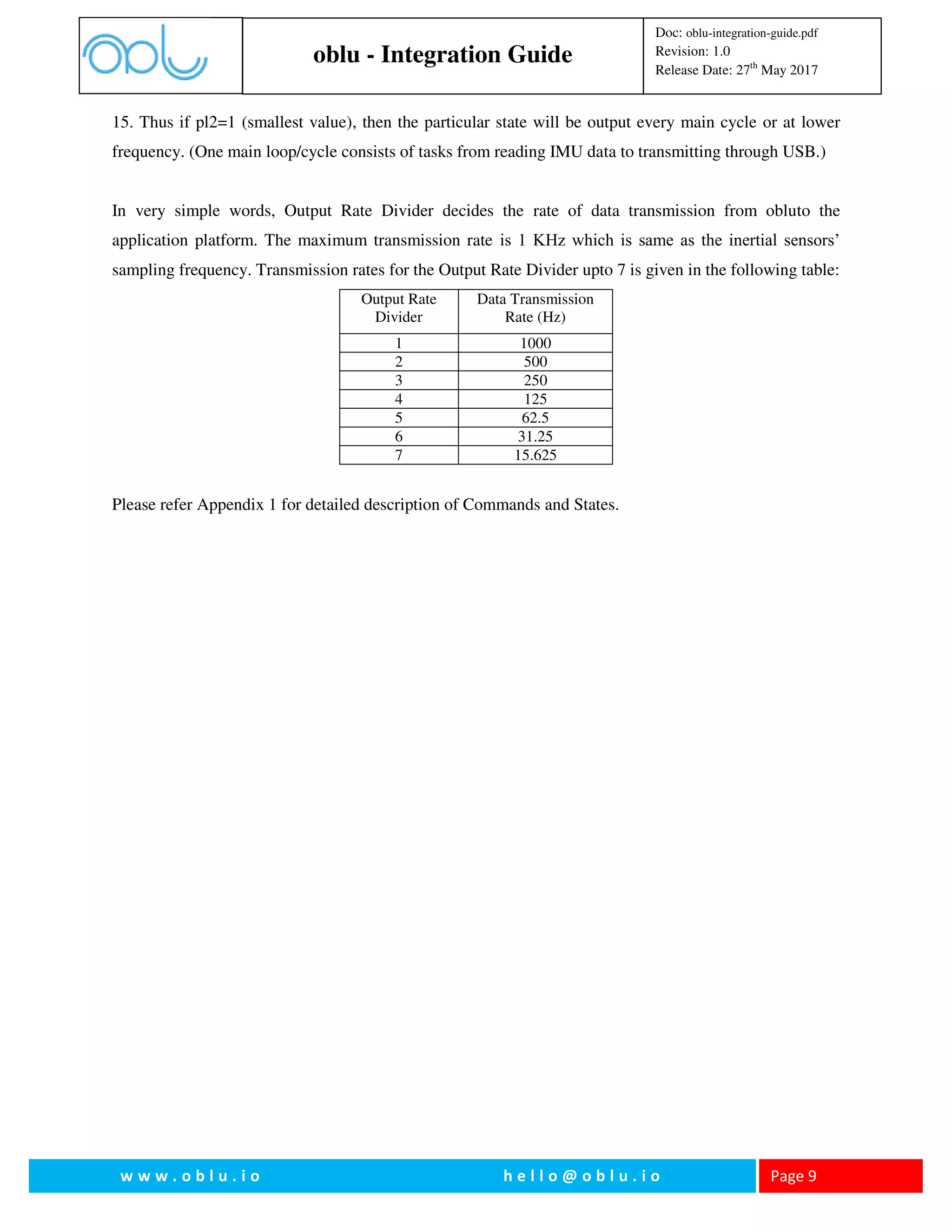
Output Rate Divider: It constitutesofonly one byte. It is used to manipulate the rate of output of the
particular state asked in this command. If the frequency of the running the whole main method/loop is ‘f’
then the frequency of output of this particular state will be f/(2^(pl2-1)). The largest value of pl2 can be
9. oblu - Integration Guide
Doc: oblu-integration-guide.pdf
Revision: 1.0
Release Date: 27th
May 2017
w w w . o b l u . i o h e l l o @ o b l u . i o Page 9
15. Thus if pl2=1 (smallest value), then the particular state will be output every main cycle or at lower
frequency. (One main loop/cycle consists of tasks from reading IMU data to transmitting through USB.)
In very simple words, Output Rate Divider decides the rate of data transmission from obluto the
application platform. The maximum transmission rate is 1 KHz which is same as the inertial sensors’
sampling frequency. Transmission rates for the Output Rate Divider upto 7 is given in the following table:
Output Rate
Divider
Data Transmission
Rate (Hz)
1 1000
2 500
3 250
4 125
5 62.5
6 31.25
7 15.625
Please refer Appendix 1 for detailed description of Commands and States.
10. oblu - Integration Guide
Doc: oblu-integration-guide.pdf
Revision: 1.0
Release Date: 27th
May 2017
w w w . o b l u . i o h e l l o @ o b l u . i o Page 10
Stepwise Dead Reckoning with Android Application Platform
As an example, we consider a specific case of using oblu for stepwise dead reckoning with an (Android)
application platform, communicating wirelessly.
The oblusends out stepwise dead reckoning data in form of packets via wireless communication, in
response to the command [52 0 52] from application platform.Below figure illustrates how the packets
look like.
Command for Stepwise
Dead reckoning data
X
Y
Z
dx
dy
dz Summation
&
Heading
oblu
(Pedestrian Dead
Reckoning Platform)
Sensor Fusion
(Displacement &
Heading change sensor)
Calibration
Compensation
ZUPT-aided
Inertial Navigation
Multiple-IMUs
Sensing
Displacement (dx, dy, dz)
Orientation (Heading change, d)
d
Figure 4 Interfacing of oblu with an application platform
Xoblu - Android Application
Fig. 5: Pedestrian Dead Reckoning (PDR) is simplified with the foot-mounted oblu. The device starts transmitting location data at
every step, on receiving start command from the application platform.
11. oblu - Integration Guide
Doc: oblu-integration-guide.pdf
Revision: 1.0
Release Date: 27th
May 2017
w w w . o b l u . i o h e l l o @ o b l u . i o Page 11
Data Packet
These packets consisted of 64 bytes.
1. Header: First 4 bytes are ‘Header’.
a. Among these 4 bytes first is the header which is STATE_OUTPUT_HEADER which is
170.
b. 2nd
and 3rd
byte jointly tells the data packet number sent by the device since the beginning
of stepwise dead reckoning. Thus the packet number is a 16-bits variable.
c. 4th
byte depicts the payload i.e. the number of bytes this data packet contains which
consists of required information asked by the user.
2. Payload: Next is the payload, which consisted of 14 elements of type ‘float’ thus comprising of
14*4=56 bytes.
a. First 4 elements consisted of the delta vector i.e. the change in position x, y, z and the
angle of rotation around z-axis (the change in the angle of the x-y plane). As these
elements are of type float, thus are of 32 bits. The change in position is between two
successive ZUPT instances, i.e. the displacement vector from one step to the next one.
b. The other 10 elements of the payload are used to form the covariance matrix, which is a
4x4 symmetric matrix, thus 10 elements. These are not used in the step-wise dead
reckoning.These are used in data fusion from two oblusin case of dual foot mounted
system.
B00B01B02B03B04B05 B58B59B60B61B62B63
Header Payload
Check
sum
B00: State of the Header
B01-B02: Data packet number
B03: Number of bytes in Payload
B04-B07: Displacement in x (Type float)
B08-B11: Displacement in y (Type float)
B12-B15: Displacement in z (Type float)
B16-B19: Change in angle around z axis (Type float)
B20-B59: 10 entries (4 bytes each) of a 4x4
symmetric covariance matrix
B62-B63: Check sum
B60-B61: Step counter
Figure 5 Data packet for stepwise dead reckoning
12. oblu - Integration Guide
Doc: oblu-integration-guide.pdf
Revision: 1.0
Release Date: 27th
May 2017
w w w . o b l u . i o h e l l o @ o b l u . i o Page 12
3. Step Counter: Next two bytes consisted of step counter, which is a counter taking record of
ZUPT instances observed. This is essentially number of times velocity of oblugoes down below
predefined threshold. Hence it is the number of steps taken by the wearer, if obluis used for foot-
mounted pedestrian tracking.
4. Checksum: The last two bytes of 64 bytes are consisted of check sum which is sum of all the
bytes received prior to these. These are usedto cross-check correctness of the data transferred.
Rotation in Application Platform
Oblu transmits tracking data with respect to its own frame which itself is not fixed with respect to
the user’s global reference frame. Therefore the data should undergo rotational transformation
before being presented to the end user in a global reference frame. (Here global refers to the
coordinate axis in which the system is initialized.)
The first four bytes of Payload are the position and heading change vector, i.e. dx, dy, dz, dθ (dθ
is the change in angle of rotation about z-axis). These values are the output from the device at
every ZUPT instance. As mentioned earlier, each set of delta values describes movement between
two successive steps. The delta valuesprior and after each ZUPT instance, are independent to
each other as the system is reset every ZUPT, i.e. the delta values in one data packet is
independent of data value in data packet transmitted just before, just after and all other. The
position and heading change vector are with reference to the coordinate frame of last ZUPT
instance.
The ‘dθ’ corresponds to the deviation in the orientation of oblu. It is rotation of the x-y plane
about the z-axis, and z-axis is always aligned with the gravity. The da is thus used for updating
the orientation of the system, and obtaining the global reference frame. The two dimensions of
displacement vector (dx, dy) are transformed to the global frame by applying rotation and thus
(x,y) in the global frame is obtained. As we do not consider any change in alignment in z-axis,
updating the z coordinate is performed by simply adding present dz to the z obtained for previous
ZUPT.
Thus x,y,zcoordinates in the global reference frame are obtained at every ZUPT.
Details are covered in Application Note. You may also refer Appendix 2 for a piece of an
example Matlab code for better understanding of implementation.
13. oblu - Integration Guide
Doc: oblu-integration-guide.pdf
Revision: 1.0
Release Date: 27th
May 2017
w w w . o b l u . i o h e l l o @ o b l u . i o Page 13
Appendix 1
1. State: Stepwise Dead Reckoning
Command: [52 0 52]
Oblu sends out data packet for stepwise dead reckoning in response to this command [2].
2. State: Processing Off
Command: [39 0 39]
Oblu terminates all the ongoing processing in response to this command. This is soft OFF button.
3. State: All Output Off
Command: [33 0 33]
If this command is passed to the system, then the transmission of data packets, would stop. But
there will be no change in the process going on inside, that all the functions would be running as
it is, just the thing is values would not be output.
4. State: Read Inertial Data
Command: [48 19 0 rd cs1 cs2]
This command is used to initiate sampling onboard inertial sensors’ data by oblu.
rd: Output rate divider
cs1, cs2: Two bytes checksum
Example:
Recommended for USB:
[48 19 0 0 67]
[40 0 0 0 15 65 0 120] (o/p data rate:1 = 1 KHz)
Recommended for Bluetooth
[48 19 0 0 67]
14. oblu - Integration Guide
Doc: oblu-integration-guide.pdf
Revision: 1.0
Release Date: 27th
May 2017
w w w . o b l u . i o h e l l o @ o b l u . i o Page 14
[40 0 0 0 15 68 0 124] (o/p data rate: 4 = 125 Hz)
5. State: Output Inertial Data
Command: [40 pl1 pl2 pl3 pl4 pl5 cs1, cs2]
Oblu outputs IMU sensors’ readings in response to this command.
Here pl1, pl2, pl3 and pl4 constitute one byte each. These are used for selecting IMUs. Consider
the pl1, pl2, pl3 and pl4 all together constitute 4 bytes i.e. 32 bits, where each bit corresponds to
one of the 32 IMUs.
Consider if we want to select the first 4 IMUs we want to have the 4 LSBs to be 1 which can be
made by having pl4 be 15 (binary: 00001111) and all the others be 0. Thus [40 0 0 0 15 1 0 56] is
a sample command selecting the first four IMUs for getting the raw inertial data. pl5 here is the
output mode byte.
Here the output consists of [axi, ayi, azi, gxi, gyi, gzi] for each IMU selected, as in Fig 2. As each of
the values corresponds to 2 bytes, thus the output is of 12 bytes for each IMU.
cs1, cs2 are two bytes checksum
Example:
Set of commands to obtain data packets containing 4 accelerometers' and 4 gyroscopes' data:
Recommended for USB:
[48 19 0 0 67]
[40 0 0 0 15 65 0 120] (o/p data rate:1 = 1 KHz)
Recommended for Bluetooth
[48 19 0 0 67]
[40 0 0 0 15 68 0 124] (o/p data rate: 4 = 125 Hz)
Here are the example data packets containing 4 accelerometers' and 4 gyroscopes' data, obtained
as a result of above set of commands (USB):
15. oblu - Integration Guide
Doc: oblu-integration-guide.pdf
Revision: 1.0
Release Date: 27th
May 2017
w w w . o b l u . i o h e l l o @ o b l u . i o Page 15
AA 00 01 34 21 C4 48 F7 00 6E 00 54 07 57 FF E4 00 05 00 17 FF 98 FF 81 F7 6A FF D2 00
13 00 11 00 7E 00 57 07 D9 FF F6 00 0B FF EF FF 9A FF 8C F7 60 FF F6 FF F0 FF FC 1C
8C
AA 00 02 34 21 C5 35 EC 00 6E 00 54 07 57 FF E2 00 04 00 16 FF 90 FF 7F F7 68 FF D4 00
13 00 11 00 68 00 56 07 D0 FF F5 00 0A FF F0 FF 8E FF 91 F7 54 FF F2 FF F2 FF FE 1C 2E
Description of the above packet:
Total packet size: 58 bytes
Header (4 bytes): AA 00 01 34 (AA - command; 00 01 - Data packet number; 34 - data packet
size)
Data packet (52 bytes): 21 C4 48 F7 00 6E 00 54 07 57 FF E4 00 05 00 17 FF 98 FF 81 F7 6A
FF D2 00 13 00 11 00 7E 00 57 07 D9 FF F6 00 0B FF EF FF 9A FF 8C F7 60 FF F6 FF F0
FF FC (First 4 bytes for time stamp; 2 bytes each for
ax1,ay1,az1,gx1,gy1,gz1,ax2,ay2,az2,gx2,gy2,gz2,ax3,ay3,az3,gx3,gy3,gz3,ax4,ay4,az4,gx4,gy4,g
z4)
Check sum (2 bytes): 1C 8C
6. State: Read IMUs’ temperature
Command: [53 0 53]
This command is used to initiate reading of internal temperature of onboard inertial sensors by
the internal controller.
7. State: Output IMU Temperature Data
Command: [40 pl1 pl2 pl3 pl4 pl5 cs]
Oblu outputs temperature of the selected IMUs in response to this command. The output
consisted of 2 bytes containing the value of temperature, for every selected IMU.
16. oblu - Integration Guide
Doc: oblu-integration-guide.pdf
Revision: 1.0
Release Date: 27th
May 2017
w w w . o b l u . i o h e l l o @ o b l u . i o Page 16
pl1, pl2, pl3 and pl4 are same as in the command for state OUTPUT_IMU_RD. pl5 is 128 + the
actual output rate divider (1, 2, 3,… etc).
cs1, cs2: Two bytes checksum
Example:
[53 0 53] (Enables reading IMUs’ internal temperature)
[40 0 0 0 15 129 0 184] (o/p data rate:1 = 1 KHz)
Here are the example data packets containing temperature information data of all the 4 IMUs,
obtained as a result of above set of commands (USB):
AA D0 28 0C 00 57 00 19 BF 16 00 1B 0F 2E 3F 9A 04 24
8. State: High precision IMU (Normal IMU)
Command: [64 pl1 cs1 cs2]
pl1 = output rate divider
cs1, cs2: checksum
With this command, oblu can be used as a single high precision IMU. The modules are capable of
giving calibration compensated and fused data from the IMU array. This means the module can
be used as a single precision IMU which outputs 3-axis acceleration and 3-axis gyroscope
data.The device outputs g’x, g’y, g’z, a’x, a’y, a’z (ref Fig 2 and Fig 3) – 4 bytes each, float type.
Below is the sample data from oblu lying tilted on a table. The data was collected at data rate
250Hz. Each packet contains 34 bytes. First 4 bytes are header (1st byte command id, 2 bytes
packet number, 1 byte payload size) and last 2 bytes are checksum. Remaining 28 bytes (also
known as payload) in sequence: 4 bytes for time stamp,12 bytes for a’x, a’y, a’zand next 12 bytes
for g’x, g’y, g’z.
AA 17 6C 1C C3 E6 7A 98 40 74 22 11 40 7B 3D 0F 41 03 7D 75 3A 16 A9 04 BC 38 C7 5C 3B 44 67 1A 0B 3C
AA 17 6D 1C C3 EA 1A 5A 40 72 2A 66 40 74 6B 15 41 02 00 56 BB 81 90 AE BB C4 02 4C 3C 15 68 7D 0B F7
AA 17 6E 1C C3 EE 02 2C 40 6E 2F AD 40 72 CF 04 41 00 D0 13 3B CE D8 92 3C 7B 8D 07 BB 6F B7 7A 0D 76
AA 17 6F 1C C3 F1 EA 29 40 71 61 98 40 79 05 2B 41 02 66 13 39 DB E9 56 3C DD 6F 45 BB 88 B3 AC 0E 24
AA 17 70 1C C3 F5 D2 27 40 76 1F C3 40 79 BB 38 41 04 59 68 3B 3B F5 01 3C 54 2B 53 BB 4C 5A C9 0C EC
AA 17 71 1C C3 F9 BA 52 40 72 AA BA 40 7C 8D A5 41 03 A5 AA BB 8B 3A FE BB 25 09 28 3B CB 04 99 0E DF
AA 17 72 1C C3 FD A2 29 40 73 B4 98 40 73 6C E6 41 02 5C 5B BB 4E 0E 26 BB F8 19 C5 3C 6C 9E F2 0E DE
AA 17 73 1C C4 01 8A 63 40 6C 6C 7B 40 76 29 56 41 01 49 FF 3A 85 78 8A 3C 05 64 A7 BC 1B 9A 3C 0C 0E
17. oblu - Integration Guide
Doc: oblu-integration-guide.pdf
Revision: 1.0
Release Date: 27th
May 2017
w w w . o b l u . i o h e l l o @ o b l u . i o Page 17
9. State: High precision IMU with bias estimation
Command: [65 pl1 cs1 cs2]
pl1 = output rate divider
cs1, cs2: checksum
This command gives the combined fused precision IMU data after calibration compensation and
adding the estimated bias. The output format will be same as the High Precision IMU (64) data
except the estimated bias is added with each data set.
10. State: Request output of state
Command: [32 pl1 pl2 cs1 cs2]
pl1 = state ID
pl2 = output mode
cs1, cs2: checksum
Requests the state connected to the state ID to be output. The output modebyte controls how the
state is output. The states are ordered according totheir IDs in the response.
Example command
[32 01 32 00 65]
Here is the output for the state ID (0X01) as a result of above set of commands (USB):
AA 06 76 04 1C FB 65 D9 03 7F
11. State: Request output of multiple states
Command:[33 pl1 pl2 pl3 pl4 pl5 pl6 pl7 pl8 pl9 cs1 cs2]
pl1-pl8 = state ID
pl9 = output mode
cs1, cs2: checksum
Requests the states connected to the state IDs to be output. The outputmode byte controls how the
state is output. The states are ordered accordingto their IDs in the response. This command is the
same as justas above withmore IDs. If zeros are given instead of the IDs, no output will be
given.Consequently, the command may be used to request output of up to 8 states.
Example command
[33 16 17 21 22 00 00 00 00 04 00 113]
Here is the output for the state ID (0X010, 0X011, 0X015, 0X016) as a result of above set of
commands (USB):
18. oblu - Integration Guide
Doc: oblu-integration-guide.pdf
Revision: 1.0
Release Date: 27th
May 2017
w w w . o b l u . i o h e l l o @ o b l u . i o Page 18
AA 05 AF 38 00 18 C4 00 00 0D 30 00 FC 2F 8800 FE 88 00 FC B8 00 FD 94 00 00 1A68 00
00 0B 80 00 FC 2E 38 00 80 00 FA B8 00 FD 40 00 00 02 66 A4 00 00 01 7317 84
12. State: Set the gravity value
Command:[6 g0 g1 g2 g3 g4 g5 g6 cs1 cs2]
g0 to g6 = g value
cs1, cs2: checksum
With this command the value of g can be input without programming the device. For e.g.to input
value of acc. due gravity as 9.81 m/s2
, then input command would be [6 9 8 1 0 0 0 0 0 24].
13. State: Calibration data value set.
Command: [36 pl1 pl2 pl3 pl4 pl5 pl6 pl7 pl8 pl9 pl10 pl11 pl12 pl13 pl14 pl15 pl16 pl17 pl18
pl19 cs1 cs2]
pl1 = select IMU position
pl2 – pl19 = 4 byte calibration data
cs1, cs2: checksum
With this command the calibration file can be input to oblu without need to reprogram the device.
pl1 is the IMU# and pl2 to pl19 are the calibration data. pl2 –pl4 are the x-axis accelerometer
calibration components, pl5-pl7 and pl8 – pl10 are y axis and z axis accelerometer calibration
components respectively. Similarly pl11-pl13, pl14-pl16 and pl17-pl19 are the x-axis, y axis and
z axis gyroscope calibration components respectively.
14. State: Input fused Accelerometer Bias
Command:[8 pl1 pl2 pl3 cs1 cs2]
pl1 – pl3 = 4 byte each input data
cs1, cs2: checksum
With this command the fused bias estimation value of the accelerometer can be input without
reprogramming the device. pl1,pl2 and pl3 are the bias estimation of the accelerometer along x, y
and z axis respectively.
15. State: Input Fused Gyroscope Bias
Command:[9 pl1 pl2 pl3 cs1 cs2]
pl1 – pl3 = 4 byte each input data
cs1, cs2: checksum
With this command the fused bias estimation value of the gyroscope can be input without
reprogram. pl1,pl2 and pl3 are the bias estimation of the gyroscope along x, y and z axis
respectively.
16. State: Calibration F & G bias
Command: [37 pl1 pl2 pl3 pl4 pl5 pl6 pl7 cs1 cs2]
19. oblu - Integration Guide
Doc: oblu-integration-guide.pdf
Revision: 1.0
Release Date: 27th
May 2017
w w w . o b l u . i o h e l l o @ o b l u . i o Page 19
pl1 = select IMU position
pl2 – pl7 = 4 byte each data
cs1, cs2: checksum;
With this command we can give the individual Bias for each IMU. Pl1 is the IMU selected and
pl2 to pl7 is the bias along x, y and z axis of accelerometer and gyroscope respectively
17. State: Set FG (Accelero and Gyro) scale
Command: [67 pl1 pl2 cs1 cs2]
pl1= fs_scale (Accelero)
pl2 = afs_scale (Gyro)
cs1, cs2: checksum;
With this command the range of the accelerometer and gyroscope can be selected. The values of
pl1 can be 0, 8, 16, 24 and pl2 can be 0, 8, 16, and 24 respectively. Please refer to Table 3 for
details:
Table 3: Accelerometer and Gyroscope scale
fs scale Range
0 ±2g
8 ±4g
16 ±8g
24 ±16g
afs scale Range
0 500o
/s
8 1000o
/s
16 1500o
/s
24 2000o
/s
18. State: Set IMUs
Command: [7 pl1 cs1 cs2]
pl1= select IMUs position
cs1, cs2: checksum;
With this command selection of IMUs is possible.Onlydifferent combinations of 1, 2 and 4 IMUs
can be selected. To select IMU #3 the command should be [7 8 0 15].
19. State: Software Version
Command: [41 cs1 cs2]
cs1, cs2: checksum;
Oblu output the version of the programmed firmware.
The example output data transmitted via USB
AA 00 01 08 00 00 00 00 01 00 00 00 01 00 B5
20. oblu - Integration Guide
Doc: oblu-integration-guide.pdf
Revision: 1.0
Release Date: 27th
May 2017
w w w . o b l u . i o h e l l o @ o b l u . i o Page 20
Header: AA 00 01 08
Version:00 00 00 00 01 00 00 00 01 (1.1)
Check sum: 00 B5
20. State: Get Device Id
Command: [25 cs1 cs2]
cs1, cs2: checksum;
Oblu give the device ID with this command.
The example output of the command is given below
AA 00 02 08 00 00 16 08 03 00 00 06 00 DB
Header:AA 00 02 08
ID:00 00 16 08 03 00 00 06
Check Sum:00 DB
N.B: For all the commands from Sl No. 12 to 18 resetting oblu will set all the values to the
default programmed values.
21. oblu - Integration Guide
Doc: oblu-integration-guide.pdf
Revision: 1.0
Release Date: 27th
May 2017
w w w . o b l u . i o h e l l o @ o b l u . i o Page 21
Appendix 2
Sample code (Matlab) for Stepwise Dead Reckoning
% Reset stepwise deadreckoning INS
fwrite(com, [52 0 52],'uint8');
fread(com,4,'uint8')
package_number_old = nan;
whileabort_flag==0
if(com.BytesAvailable>=64)
header = fread(com,2,'uint8'); % Header + number + Payload size (-) 4, (+)2
payload = fread(com,14,'float');
step_counter = fread(com,1,'uint16'); % Step counter
fread(com,1,'uint16'); % Checksum
fprintf(file,'%i %i %12.9f %12.9f %12.9f %12.9f %12.9f %12.9f %12.9f %12.9f %12.9f %12.9f %12.9f %12.9f %12.9f
%12.9fn',step_counter,payload);% for USB
dx = payload(1:4);
dP = Pvec2Pmat(payload(5:14));
pdef=find(eig(dP)<=0);
ifisempty(pdef)
chol(dP,'lower');
end
[x_swP_sw] = stepwise_dr_tu(x_sw,P_sw,dx,dP);
figure(1)
plot([x_sw(1) x_sw_old(1)],[x_sw(2) x_sw_old(2)],'b');
axis equal;
drawnow;
x_sw_old = x_sw;
P_sw_old = P_sw;
end
end
% Stop output
fwrite(com, [50 0 50],'uint8'); % Processing off
fwrite(com, [34 0 34],'uint8'); % all output off
----------------------------------------
% stepwise_dr_tu
function [x2_out P2_out] = stepwise_dr_tu(x2_in,P2_in,dx2,dP)
% Input matrix
sin_phi = sin(x2_in(4));
cos_phi = cos(x2_in(4));
dR = [cos_phi -sin_phi 0 0;
22. oblu - Integration Guide
Doc: oblu-integration-guide.pdf
Revision: 1.0
Release Date: 27th
May 2017
w w w . o b l u . i o h e l l o @ o b l u . i o Page 22
sin_phicos_phi 0 0;
0 0 1 0;
0 0 0 1];
F = [1 0 0 -sin_phi*dx2(1)-cos_phi*dx2(2);
0 1 0 cos_phi*dx2(1)-sin_phi*dx2(2);
0 0 1 0;
0 0 0 1];
% Update upper layer system
x2_out = x2_in+dR*dx2;
P2_out = F*P2_in*F' + dR*dP*dR';
end
23. oblu - Integration Guide
Doc: oblu-integration-guide.pdf
Revision: 1.0
Release Date: 27th
May 2017
w w w . o b l u . i o h e l l o @ o b l u . i o Page 23
Appendix 3:
How to set calibration parameters using Matlab without compiling oblu’s firmware
1. Generate calibration file using calibration scripts
2. Convert entries of calibration file in desired format
3. Use set of commands described earlier in this document to write Matlab script
A. Calibration output file consists of fused accelerometer bias (ACC_BIAS) and fused gyroscope
bias (GYRO_BIAS). It also consists of calibration matrix. The first 18 elements of each row is
the calibration gain and the next 6 element is the individual bias of each IMUs. Oblu consists of 4
IMUs so rest of the elements 28 calibration rows is 0.
An example of the calibration file is given below.
#define FLOG2_NR_IMU 2
#define ACC_BIAS { 321455, -381480, -1784994 }
#define GYRO_BIAS { -109378, 807557, -314605 }
#define CALIBRATION_MATRIX
{
{ 32737, 0, 0, -21, 32889, 0, 113, -76, 32779, 32768, 0, 0, 0, 32768, 0, 0, 0, 32768, -189318, -
1285370, -10636239, 217070, 771033, 89464 },
{ -258, -32733, 112, -32949, 259, -115, 127, -270, -32657, -258, -32766, 112, -32766, 257, -115, 113, -113, -
32767, 1031829, 231703, 2583073, -332858, 132476, -843920 },
{ 32582, -44, 181, 43, 32848, -47, -408, 4, 32552, 32767, -44, 182, 44, 32768, -47, -182, 48, 32767, -
233539, -870378, -4025710, -585304, -602875, 44841 },
{ 56, -32663, 128, -32840, -62, -281, 420, 96, -32611, 60, -32767, 129, -32765, -62, -280, 281, -128, -32765,
727064, 381943, 4940699, 261427, 2930711, -535587 },
{0, 0, 0, 0,0,0,0,0,0,0,0,0,0,0,0,0,0,0,0,0,0,0,0,0},
{0, 0, 0, 0, 0, 0, 0, 0, 0, 0, 0, 0, 0, 0, 0, 0, 0, 0, 0, 0, 0, 0, 0, 0},
{0, 0, 0, 0, 0, 0, 0, 0, 0, 0, 0, 0, 0, 0, 0, 0, 0, 0, 0, 0, 0, 0, 0, 0},
{0, 0, 0, 0, 0, 0, 0, 0, 0, 0, 0, 0, 0, 0, 0, 0, 0, 0, 0, 0, 0, 0, 0, 0},
{0, 0, 0, 0, 0, 0, 0, 0, 0, 0, 0, 0, 0, 0, 0, 0, 0, 0, 0, 0, 0, 0, 0, 0},
{0, 0, 0, 0, 0, 0, 0, 0, 0, 0, 0, 0, 0, 0, 0, 0, 0, 0, 0, 0, 0, 0, 0, 0},
{0, 0, 0, 0, 0, 0, 0, 0, 0, 0, 0, 0, 0, 0, 0, 0, 0, 0, 0, 0, 0, 0, 0, 0},
{0, 0, 0, 0, 0, 0, 0, 0, 0, 0, 0, 0, 0, 0, 0, 0, 0, 0, 0, 0, 0, 0, 0, 0},
{0, 0, 0, 0, 0, 0, 0, 0, 0, 0, 0, 0, 0, 0, 0, 0, 0, 0, 0, 0, 0, 0, 0, 0},
{0, 0, 0, 0, 0, 0, 0, 0, 0, 0, 0, 0, 0, 0, 0, 0, 0, 0, 0, 0, 0, 0, 0, 0},
{0, 0, 0, 0, 0, 0, 0, 0, 0, 0, 0, 0, 0, 0, 0, 0, 0, 0, 0, 0, 0, 0, 0, 0},
{0, 0, 0, 0, 0, 0, 0, 0, 0, 0, 0, 0, 0, 0, 0, 0, 0, 0, 0, 0, 0, 0, 0, 0},
{0, 0, 0, 0, 0, 0, 0, 0, 0, 0, 0, 0, 0, 0, 0, 0, 0, 0, 0, 0, 0, 0, 0, 0},
24. oblu - Integration Guide
Doc: oblu-integration-guide.pdf
Revision: 1.0
Release Date: 27th
May 2017
w w w . o b l u . i o h e l l o @ o b l u . i o Page 24
{0, 0, 0, 0, 0, 0, 0, 0, 0, 0, 0, 0, 0, 0, 0, 0, 0, 0, 0, 0, 0, 0, 0, 0},
{0, 0, 0, 0, 0, 0, 0, 0, 0, 0, 0, 0, 0, 0, 0, 0, 0, 0, 0, 0, 0, 0, 0, 0},
{0, 0, 0, 0, 0, 0, 0, 0, 0, 0, 0, 0, 0, 0, 0, 0, 0, 0, 0, 0, 0, 0, 0, 0},
{0, 0, 0, 0, 0, 0, 0, 0, 0, 0, 0, 0, 0, 0, 0, 0, 0, 0, 0, 0, 0, 0, 0, 0},
{0, 0, 0, 0, 0, 0, 0, 0, 0, 0, 0, 0, 0, 0, 0, 0, 0, 0, 0, 0, 0, 0, 0, 0},
{0, 0, 0, 0, 0, 0, 0, 0, 0, 0, 0, 0, 0, 0, 0, 0, 0, 0, 0, 0, 0, 0, 0, 0},
{0, 0, 0, 0, 0, 0, 0, 0, 0, 0, 0, 0, 0, 0, 0, 0, 0, 0, 0, 0, 0, 0, 0, 0},
{0, 0, 0, 0, 0, 0, 0, 0, 0, 0, 0, 0, 0, 0, 0, 0, 0, 0, 0, 0, 0, 0, 0, 0},
{0, 0, 0, 0, 0, 0, 0, 0, 0, 0, 0, 0, 0, 0, 0, 0, 0, 0, 0, 0, 0, 0, 0, 0},
{0, 0, 0, 0, 0, 0, 0, 0, 0, 0, 0, 0, 0, 0, 0, 0, 0, 0, 0, 0, 0, 0, 0, 0},
{0, 0, 0, 0, 0, 0, 0, 0, 0, 0, 0, 0, 0, 0, 0, 0, 0, 0, 0, 0, 0, 0, 0, 0},
{0, 0, 0, 0, 0, 0, 0, 0, 0, 0, 0, 0, 0, 0, 0, 0, 0, 0, 0, 0, 0, 0, 0, 0},
{0, 0, 0, 0, 0, 0, 0, 0, 0, 0, 0, 0, 0, 0, 0, 0, 0, 0, 0, 0, 0, 0, 0, 0},
{0, 0, 0, 0, 0, 0, 0, 0, 0, 0, 0, 0, 0, 0, 0, 0, 0, 0, 0, 0, 0, 0, 0, 0},
{0, 0, 0, 0, 0, 0, 0, 0, 0, 0, 0, 0, 0, 0, 0, 0, 0, 0, 0, 0, 0, 0, 0, 0},
B. Each of the parameters in the above example is represented in float (4 bytes). The each entry in
the example file is formatted to four separate bytes, for the purpose of using commands. Below
are the examples of formatting entry into 4 separate bytes:
(i) 321455 = 0x4E7AF;
Hexadecimal 00 04 E7 AF
Decimal 0 4 231 175
Now 321455 is replaced by 0 4 231 175
(ii) -109378 = 0XFFFE54BE
Hexadecimal FF FE 54 BE
Decimal 255 254 84 190
Similarly -109378 is replaced by 255 254 84 190
This format is followed for all the elements for calibration output file.
Each row of the calibration matrix consists of (18x4) 72 bytes representing the calibration gain shown
below as imu_mask(i) and the individual IMU bias consists of (6x4) 24 bytes each depicted as
imu_bias(i) .
The calibration is now re-written as following, in the new format:
f_log2 = 4;
f_bias = [0 4 231 175 255 25 0 45 216 255 228 195 94];
g_bias = [255 254 84 190 0 12 82 133 255 251 51 19];
26. oblu - Integration Guide
Doc: oblu-integration-guide.pdf
Revision: 1.0
Release Date: 27th
May 2017
w w w . o b l u . i o h e l l o @ o b l u . i o Page 26
command_calib_mat = [header_calib_mat imu_pos3 imu_mask3];
command_calib_mat = [command_calib_mat (sum(command_calib_mat)-mod(sum(command_calib_mat),256))/256
mod(sum(command_calib_mat),256)];
fwrite(com,command_calib_mat,'uint8');
command_c_bias = [header_c_bias imu_pos0 imu_bias0];
command_c_bias = [command_c_bias (sum(command_c_bias)-mod(sum(command_c_bias),256))/256 mod(sum(command_c_bias),256)];
fwrite(com,command_c_bias,'uint8');
command_c_bias = [header_c_bias imu_pos1 imu_bias1];
command_c_bias = [command_c_bias (sum(command_c_bias)-mod(sum(command_c_bias),256))/256 mod(sum(command_c_bias),256)];
fwrite(com,command_c_bias,'uint8');
command_c_bias = [header_c_bias imu_pos2 imu_bias2];
command_c_bias = [command_c_bias (sum(command_c_bias)-mod(sum(command_c_bias),256))/256 mod(sum(command_c_bias),256)];
fwrite(com,command_c_bias,'uint8');
command_c_bias = [header_c_bias imu_pos3 imu_bias3];
command_c_bias = [command_c_bias (sum(command_c_bias)-mod(sum(command_c_bias),256))/256 mod(sum(command_c_bias),256)];
fwrite(com,command_c_bias,'uint8');
fwrite(com,[50 0 50],'uint8'); % Stop processing
fwrite(com,[34 0 34],'uint8'); % Stop output (and empty buffers)
whilecom.BytesAvailable
fread(com,com.BytesAvailable,'uint8');
end
fclose(com);
Here header_f_log = Log2(No. of IMUs)