Download to read offline


![Instruction Manual
Doc: MIMUscope-Manual-1v1.pdf
Revision: 1.1
Release Date: 20
th
May 2017
w w w . o b l u . i o h e l l o @ o b l u . i o Page 22
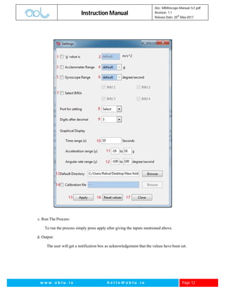
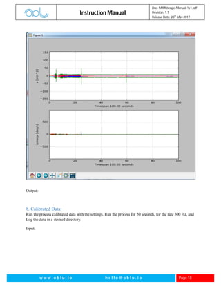
Appendix:
Real Time IMU:
Command = [64 pl1 cs1 cs2]
pl1 = output rate divider; cs1, cs2 = checksum
Acknowledgement = “0xA0 0x40 0x00 0xE0” + Real Time IMU packets
0xA0: Acknowledgement state, 0x40 = Start command state, 0x00 0xE0 = Checksum
The device is capable of giving calibration compensated and fused data from the IMU array. This means
the device can be used as a single precision IMU which outputs 3-axis acceleration and 3-axis gyroscope
data. The device outputs gx, gy, gz, ax, ay, az (ref Fig 2 and Fig 3) – 4 bytes each, float type.
B00 = Start Code B08-31 = Payload
B01-2 = Data Packet Number B08-11 = ax, B12-15 = ay, B16-19 = az
B03 = Number of bytes in payload B20-23 = gx, B24-27 = gy, B28-31 = gz
B04-07 = Time stamp (unsigned int) B32-33 = checksum
Raw Data:
Command 1 = [48 19 0 cs1 cs2]
cs1, cs2: Two bytes checksum
This command is used to initiate sampling on board inertial sensors’ data by the oblu device.
Acknowledgement = --
Command 2 = [40 pl1 pl2 pl3 pl4 pl5 cs1 cs2]
pl1, pl2, pl3, pl4 all together consists of 32bits. Each bit corresponds to particular IMU. Thus pl1-pl4 are
used to select IMUs.
pl5* is the actual rate divider+ 64.
cs1, cs2: Two bytes checksum](https://image.slidesharecdn.com/mimuscope-manual-1v1-170520005430/85/MIMUscope-Instruction-Manual-22-320.jpg)
![Instruction Manual
Doc: MIMUscope-Manual-1v1.pdf
Revision: 1.1
Release Date: 20
th
May 2017
w w w . o b l u . i o h e l l o @ o b l u . i o Page 23
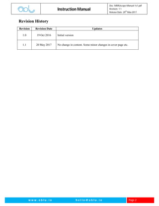
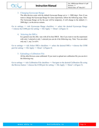
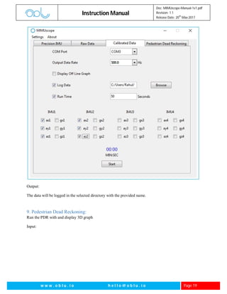
Acknowledgement = “0xA0 0x28 0x00 0xC8” + Raw Data packets
0xA0: Acknowledgement state, 0x40 = Start command state, 0x00 0xC8 = Checksum
B00 = Start Code B20-31 = ax2, ay2, az2, gx2, gy2, gz2 (IMU 2)
B01-02 = Packet Number B32-43 = ax3, ay3, az3, gx3, gy3, gz3 (IMU 3)
B04-07 = Time stamp B44-55 = ax4, ay4, az4, gx4, gy4, gz4 (IMU 4)
B08-55 = Payload B56-57 = Checksum
B08-19 = ax1, ay1, az1, gx1, gy1, gz1 (IMU 1)
Each Sensor’s Calibrated Data:
Command = [24 pl1 pl2 pl3 pl4 pl5 cs1 cs2]
pl1, pl2, pl3, pl4 all together consists of 32bits. Each bit corresponds to particular IMU. Thus pl1-pl4 are
used to select IMUs.
pl5* is the actual rate divider+ 64.
cs1, cs2: Two bytes checksum
Acknowledgement = 0xA0 0x18 0x00 0xB2" + Each Sensors Calibrated Data Packets
0xA0: Acknowledgement state, 0x34 = Start command state, 0x00 0xB2 = Checksum
B00 = Start Code B32-55 = ax2, ay2, az2, gx2, gy2, gz2 (IMU 2)
B01-02 = Packet Number B56-79 = ax3, ay3, az3, gx3, gy3, gz3 (IMU 3)](https://image.slidesharecdn.com/mimuscope-manual-1v1-170520005430/85/MIMUscope-Instruction-Manual-23-320.jpg)
![Instruction Manual
Doc: MIMUscope-Manual-1v1.pdf
Revision: 1.1
Release Date: 20
th
May 2017
w w w . o b l u . i o h e l l o @ o b l u . i o Page 24
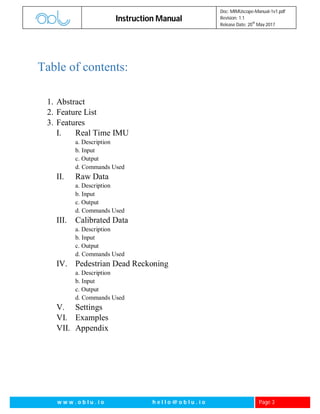
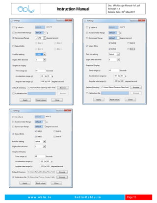
B04-07 = Time stamp B80-103 = ax4, ay4, az4, gx4, gy4, gz4 (IMU 4)
B08-103 = Payload B104-105 = Checksum
B08-31 = ax1, ay1, az1, gx1, gy1, gz1 (IMU 1)
Stepwise PDR
Command = [52 00 52] or [0x34 0x00 0x34] (in hex)
Acknowledgement = "0xA0 0x34 0x00 0xD4" + PDR Packets
0xA0: Acknowledgement state, 0x34 = Start command state, 0x00 0xD4 = Checksum
B00: State of the Header B16-B19: da: Change in angle around z axis (Type float)
B01-B02: Data packet number B20-B59: 10 entries (4 bytes each) of a 4x4 symmetric
B03: Number of bytes in Payload covariance matrix
B04-B07: dx: Displacement in x (Type float) B62-B63: Check sum
B08-B11: dy: Displacement in y (Type float) B60-B61: Step counter
B12-B15: dz: Displacement in z (Type float)
To change ‘g’ value
Command = [6 d1 f1 f2 f3 f4 f5 f6 cs1 cs2] d1: before decimal digit and f1-6 represent the 6 digits after
decimal
Example: To set ‘g’ value to 9.81 the command should be [06 09 08 01 00 00 00 00 00 24]
Acknowledgement = “0xA0 0x06 00 0xA6”
0xA0: Acknowledgement state, 0x06 = Start command state, 0x00 0xA6 = Checksum
To change accelerometer and gyroscope range:
Command =[67 fscale gscale cs1 cs2]
f scale = 4 // 1 for +/- 2g, 2 for +/- 4g, 3 for +/- 8g, 4 for +/- 16g,
G scale = 4// 1 for +/- 250 deg/s, 2 for +/- 500deg/s, 3 for +/- 1000deg/s, 4 for +/- 2000deg/s,
cs1, cs2 = 2 byte checksum
Example: To set a scale +/- 2g and g scale [/-250 deg/s the command should be [67 01 01 01 00 69]
Acknowledgement = “0xA0 0x43 00 0xCF”
0xA0: Acknowledgement state, 0x43 = Start command state, 0x00 0xCF = Checksum](https://image.slidesharecdn.com/mimuscope-manual-1v1-170520005430/85/MIMUscope-Instruction-Manual-24-320.jpg)
![Instruction Manual
Doc: MIMUscope-Manual-1v1.pdf
Revision: 1.1
Release Date: 20
th
May 2017
w w w . o b l u . i o h e l l o @ o b l u . i o Page 25
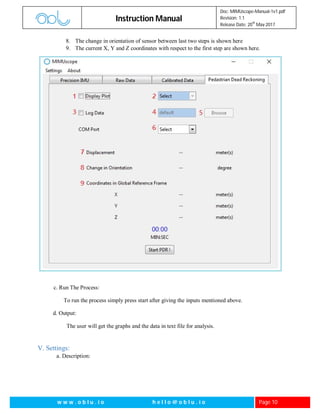
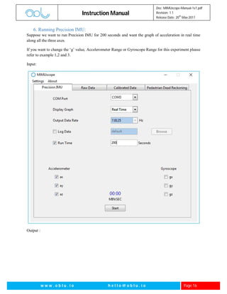
To select IMUs out of 4:
Command = [07 00 00 00 se cs1 cs2]
In se byte the first bit from left corresponds to IMU1, second to IMU2 and so on. Bit value of 1 means
that IMU is selected and Bit value of 0 means IMU is not selected.
Select 0001 => 1 => only imu1 selected
0010 =>2 => only imu2 selected
0100 =>4 => only imu3 selected
1000 =>8 => only imu4 selected
Like this if we want to select imu2 and imu4 the command should be [07 00 00 00 10 00 17]
Acknowledgement = “0xA0 0x07 0x00 0xA7”
0xA0: Acknowledgement state, 0x07 = Start command state, 0x00 0xA7 = Checksum](https://image.slidesharecdn.com/mimuscope-manual-1v1-170520005430/85/MIMUscope-Instruction-Manual-25-320.jpg)

The Mimuscope instruction manual provides detailed guidance on using the Mimuscope software, a Windows-based interface for OBLO devices that analyzes gait and provides real-time data plotting for accelerometers and gyroscopes. It outlines features such as raw and calibrated data processing, pedestrian dead reckoning (PDR), settings adjustments, and example use cases for various applications like mapping and robotics. Released in May 2017, the manual includes revision history, comprehensive instructions for input and output handling, and various GUI features to enhance user interaction.


![[IJCT-V3I2P17] Authors: Sheng Lai, Xiaohua Meng, Dongqin Zheng](https://cdn.slidesharecdn.com/ss_thumbnails/ijct-v3i2p17-160609055723-thumbnail.jpg?width=640&height=640&fit=bounds)