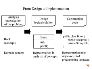
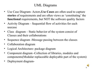
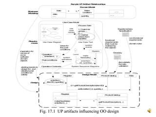
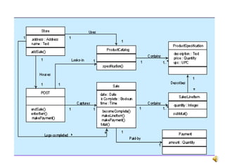
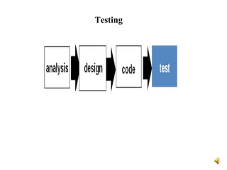
Object-Oriented Analysis
and Design
(Overview)
Objectives
The student should be made to:
– Learn the basics of OO analysis and design
skills
– Learn the UML design diagrams
– Learn to map design to code
– Be exposed to the various testing techniques.
2
Agenda
• Introduction to OOAD
• UML Diagrams
• Implementation
• OO Testing
3
OOA
• Object-Oriented Analysis (Overview)
– An investigation of the problem (rather than how a solution is defined)
– During OO analysis, there is an emphasis on finding and describing the
objects (or concepts) in the problem domain.
– For example, concepts in a Library Information System include Book,
and Library.
– High level views found in the application domain.
– Oftentimes called domain objects; entities.
4
OOD
• Object-Oriented Design
– Emphasizes a conceptual solution that fulfills the requirements.
– Need to define software objects and how they collaborate to meet the
requirements.
– For example, in the Library Information System, a Book software object
may have a title attribute and a getChapter method.
• What are the methods needed to process the attributes?
• Designs are implemented in a programming language.
– In the example, we will have a Book class in Java.
5
• Analysis: - investigate the problem and the requirements.
– What is needed? Required functions? Investigate domain objects.
– Problem Domain
– The Whats of a system.
– Do the right thing (analysis)
• Design:
– Conceptual solution that meets requirements.
– Not an implementation
– E.g. Describe a database schema and software objects.
– Avoid the CRUD activities and commonly understood functionality.
– The Solution Domain
– The ‘Hows’ of the system
– Do the thing right (design)
6
UML
• The Unified Modeling Language (UML) is a standard
diagramming notation; Visual representation of real world
domain
• It is NOT OOA/OOD or a method
• Only a notation for capturing objects and the relationships
among objects (dependency; inheritance; realizes; aggregates, . .)
• UML is language-independent
• Analysis and design provide software “blueprints” captured in
UML.
• Blueprints serve as a tool for thought and as a form of
communication with others.
7
8
From Design to Implementation
Book
title
print()
public class Book {
public void print();
private String title;
}
Book
(concept)
Analysis
investigation
of the problem
Design
logical solution
Construction
code
Domain concept Representation in
analysis of concepts
Representation in an
object-oriented
programming language.
UML Diagrams
• Use Case Diagram- Actors,Use Cases are often used to capture
stories of requirements and are often views as ‘constituting’ the
functional requirements, but NOT the software quality factors
• Activity Diagram – Sequential flow of activities for each
usecase
• Class diagram – Static behavior of the system consist of
Classes and their collaborations
• Sequence diagram -Message passing between the classes
• Collaboration diagram
• Logical Architecture- package diagram
• Component diagram -Collection of libraries, modules and
components(Modular replaceable deployable part of the system)
• Deployment diagram-
9
Fig. 17.1 UP artifacts influencing OO design
Operation:
enterItem(…)
Post-conditions:
- . . .
OperationContracts
Sale
date
. . .
Sales
LineItem
quantity
1..*1 . . .
. . .
DomainModel
Use-CaseModel
DesignModel
: Register
enterItem
(itemID, quantity)
: ProductCatalog
d=getProductDescription(itemID)
addLineItem( d, quantity)
: Sale
Require-
ments
Business
Modeling
Design
SampleUPArtifact Relationships
: System
enterItem
(id, quantity)
Use Case Text
System Sequence Diagrams
make
NewSale()
system
events
Cashier
Process
Sale
: Cashier
use
case
names
system
operations
Use Case Diagram
Supplementary
Specification
Glossary
startingeventsto
designfor, and
detailedpost-
conditionto
satisfy
ProcessSale
1. Customer
arrives...
2. ...
3. Cashier
entersitem
identifier.
inspirationfor
namesof
some
software
domain
objects
functional
requirements
that must be
realizedby
theobjects
ideasfor
thepost-
conditions
Register
...
makeNewSale()
enterItem(...)
...
ProductCatalog
...
getProductDescription(...)
...
1*
non-functional
requirements
domainrules
itemdetails,
formats,
validation
Package Diagrams
• Logical Architecture and Layers:
• Logical architecture: the large-scale organization of software
classes into packages, subsystems, and layers.
• Layer: a very coarse-grained grouping of classes, packages, or
subsystems that has cohesive responsibility for a major aspect of
the system.
• Layered Architectures
• Typical layers in an OO system:
– User Interface
– Application Logic and Domain Objects
– Technical Services
12
13
Basic Terms: Iterative, Evolutionary, and Agile
• Iterative - the entire project will be composed of min-projects
and will iterate the same activities again and again (but on
different part of the project AND with different emphases) until
completion.
• Evolutionary (or incremental) - the software grows by
increments (to be opposed to the traditional, and somewhat old-
fashioned, Waterfall model of software development).
• Agile - we will use a light approach to software development
rather than a very rigid one
• This kind of approach seems better at treating software
development as a problem solving activity;
14
Unified Process:
•The Unified Process is a popular iterative software
development process for OO systems
•Iterative and evolutionary development involves
relatively early programming and testing of a partial
system, in repeated cycles.
•Four Phases:
– Inception- Vague vision,Scope,Estimates
– Elaboration – Detailed Vision, Core
Architectures,Resolving Risks
– Construction - Implementation
– Transition - Deloyment
Unified Process Model:
Implementation
• Mapping design to code:
• Process: Write source code for
– Class and interface definitions
– Method definitions
16
Testing
OO Testing-Cont..
• Object-Oriented Testing Activities
• Review OOA and OOD models
• Class testing after code is written
Class Testing(Unit Testing):
Smallest testable unit is the encapsulated class
• Integration testing within subsystems
• Integration testing as subsystems are added to the system
• Validation testing based on OOA use-cases
GUI Testing:
• GUI Testing includes the application behaviour towards
keyboard and mouse movements and how different GUI objects
such as toolbars, buttons, menubars, dialog boxes, edit fields,
lists, behavior to the user input.
18
19

Object oriented analysis & Design- Overview

  • 1.
  • 2.
    Objectives The student shouldbe made to: – Learn the basics of OO analysis and design skills – Learn the UML design diagrams – Learn to map design to code – Be exposed to the various testing techniques. 2
  • 3.
    Agenda • Introduction toOOAD • UML Diagrams • Implementation • OO Testing 3
  • 4.
    OOA • Object-Oriented Analysis(Overview) – An investigation of the problem (rather than how a solution is defined) – During OO analysis, there is an emphasis on finding and describing the objects (or concepts) in the problem domain. – For example, concepts in a Library Information System include Book, and Library. – High level views found in the application domain. – Oftentimes called domain objects; entities. 4
  • 5.
    OOD • Object-Oriented Design –Emphasizes a conceptual solution that fulfills the requirements. – Need to define software objects and how they collaborate to meet the requirements. – For example, in the Library Information System, a Book software object may have a title attribute and a getChapter method. • What are the methods needed to process the attributes? • Designs are implemented in a programming language. – In the example, we will have a Book class in Java. 5
  • 6.
    • Analysis: -investigate the problem and the requirements. – What is needed? Required functions? Investigate domain objects. – Problem Domain – The Whats of a system. – Do the right thing (analysis) • Design: – Conceptual solution that meets requirements. – Not an implementation – E.g. Describe a database schema and software objects. – Avoid the CRUD activities and commonly understood functionality. – The Solution Domain – The ‘Hows’ of the system – Do the thing right (design) 6
  • 7.
    UML • The UnifiedModeling Language (UML) is a standard diagramming notation; Visual representation of real world domain • It is NOT OOA/OOD or a method • Only a notation for capturing objects and the relationships among objects (dependency; inheritance; realizes; aggregates, . .) • UML is language-independent • Analysis and design provide software “blueprints” captured in UML. • Blueprints serve as a tool for thought and as a form of communication with others. 7
  • 8.
    8 From Design toImplementation Book title print() public class Book { public void print(); private String title; } Book (concept) Analysis investigation of the problem Design logical solution Construction code Domain concept Representation in analysis of concepts Representation in an object-oriented programming language.
  • 9.
    UML Diagrams • UseCase Diagram- Actors,Use Cases are often used to capture stories of requirements and are often views as ‘constituting’ the functional requirements, but NOT the software quality factors • Activity Diagram – Sequential flow of activities for each usecase • Class diagram – Static behavior of the system consist of Classes and their collaborations • Sequence diagram -Message passing between the classes • Collaboration diagram • Logical Architecture- package diagram • Component diagram -Collection of libraries, modules and components(Modular replaceable deployable part of the system) • Deployment diagram- 9
  • 10.
    Fig. 17.1 UPartifacts influencing OO design Operation: enterItem(…) Post-conditions: - . . . OperationContracts Sale date . . . Sales LineItem quantity 1..*1 . . . . . . DomainModel Use-CaseModel DesignModel : Register enterItem (itemID, quantity) : ProductCatalog d=getProductDescription(itemID) addLineItem( d, quantity) : Sale Require- ments Business Modeling Design SampleUPArtifact Relationships : System enterItem (id, quantity) Use Case Text System Sequence Diagrams make NewSale() system events Cashier Process Sale : Cashier use case names system operations Use Case Diagram Supplementary Specification Glossary startingeventsto designfor, and detailedpost- conditionto satisfy ProcessSale 1. Customer arrives... 2. ... 3. Cashier entersitem identifier. inspirationfor namesof some software domain objects functional requirements that must be realizedby theobjects ideasfor thepost- conditions Register ... makeNewSale() enterItem(...) ... ProductCatalog ... getProductDescription(...) ... 1* non-functional requirements domainrules itemdetails, formats, validation
  • 12.
    Package Diagrams • LogicalArchitecture and Layers: • Logical architecture: the large-scale organization of software classes into packages, subsystems, and layers. • Layer: a very coarse-grained grouping of classes, packages, or subsystems that has cohesive responsibility for a major aspect of the system. • Layered Architectures • Typical layers in an OO system: – User Interface – Application Logic and Domain Objects – Technical Services 12
  • 13.
    13 Basic Terms: Iterative,Evolutionary, and Agile • Iterative - the entire project will be composed of min-projects and will iterate the same activities again and again (but on different part of the project AND with different emphases) until completion. • Evolutionary (or incremental) - the software grows by increments (to be opposed to the traditional, and somewhat old- fashioned, Waterfall model of software development). • Agile - we will use a light approach to software development rather than a very rigid one • This kind of approach seems better at treating software development as a problem solving activity;
  • 14.
    14 Unified Process: •The UnifiedProcess is a popular iterative software development process for OO systems •Iterative and evolutionary development involves relatively early programming and testing of a partial system, in repeated cycles. •Four Phases: – Inception- Vague vision,Scope,Estimates – Elaboration – Detailed Vision, Core Architectures,Resolving Risks – Construction - Implementation – Transition - Deloyment
  • 15.
  • 16.
    Implementation • Mapping designto code: • Process: Write source code for – Class and interface definitions – Method definitions 16
  • 17.
  • 18.
    OO Testing-Cont.. • Object-OrientedTesting Activities • Review OOA and OOD models • Class testing after code is written Class Testing(Unit Testing): Smallest testable unit is the encapsulated class • Integration testing within subsystems • Integration testing as subsystems are added to the system • Validation testing based on OOA use-cases GUI Testing: • GUI Testing includes the application behaviour towards keyboard and mouse movements and how different GUI objects such as toolbars, buttons, menubars, dialog boxes, edit fields, lists, behavior to the user input. 18
  • 19.

Editor's Notes

  • #14 Explain Iterative, Evolutionary, Agile
  • #15 why do you think it works better this way for software?