Download as PDF, PPTX


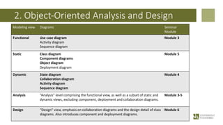


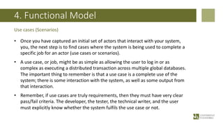


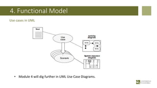


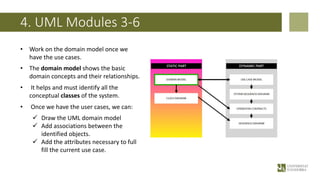


This document provides an overview of Module 3 which covers object-oriented analysis and design (OOAD) and the functional model. It discusses how OOAD uses the Unified Modeling Language (UML) to represent different components and interactions of a software system through various diagrams. Specifically, it explains that Module 3 will focus on the functional model, which illustrates system functionality and user interactions, while Modules 4-6 will cover the dynamic and static models. The document also distinguishes between analysis, which understands system requirements, and design, which produces specifications to be implemented.


![Lect 1 Number systems and base conversions. [Autosaved].pptx](https://cdn.slidesharecdn.com/ss_thumbnails/lect1numbersystemsandbaseconversions-260111134109-67c2d865-thumbnail.jpg?width=640&height=640&fit=bounds)


