This document provides an overview of the CST 205 Object Oriented Programming using Java course, which covers approaches to software design like object oriented design, UML diagrams including class diagrams, and an introduction to Java programming. It then discusses class diagrams in more detail, including UML notation for classes, member visibility and scope, relationships between classes like association and generalization, and provides an example class diagram for a pizza order system.

![UML notation for Class
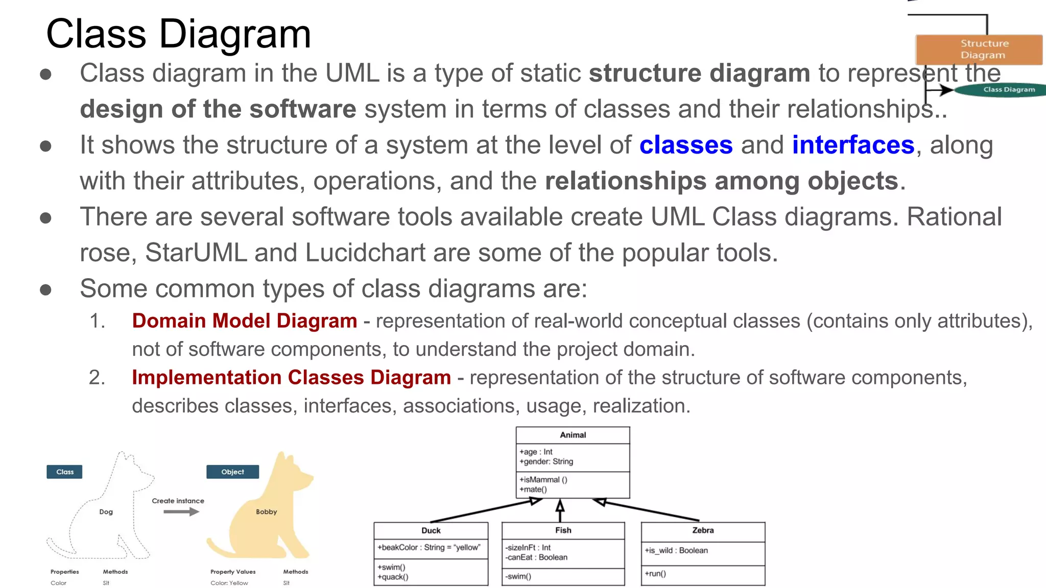
A class notation consists of three parts:
1. Class Name (mandatory):
○ The name of the class appears in the first
partition.
2. Class Attributes[optional]:
○ An attribute is a named property of a class that
describes the object being modeled
○ Attributes are shown in the second partition.
○ The attribute type is shown after the colon.
○ Derived attribute is designated by a preceding ‘/’
○ Attributes map onto member variables (data members) in code.
3. Class Operations(Methods)[optional]:
○ Operations are shown in the third partition. They are services the class provides.
○ The return type of a method is shown after the colon at the end of the method signature.
○ Operations map onto class methods in code](https://image.slidesharecdn.com/lecture-4-oopclassdiagram-210203150934/75/Lecture-4-oop-class-diagram-4-2048.jpg)