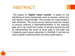
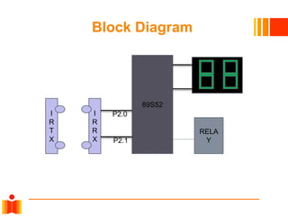
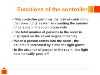
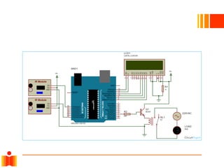
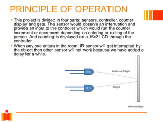
Indian Institute of Technology
Hyderabad
AUTOMATIC ROOM LIGHT
CONTROLLER
by
Swaraj Dhumal
Akash Nale
Omkar Nale
Suraj Khomane
ABSTRACT
The project of “Digital visitor counter” is based on the
interfacing of some components such as sensors, motors etc.
with Arduino microcontroller. This counter can count people in
both directions. This circuit can be used to count the number
of persons entering a hall/mall/home/office in the entrance
gate and it can count the number of persons leaving the hall
by decrementing the count at same gate or exit gate and
it depends upon sensor placement in mall/hall. It can also be
used at gates of parking areas and other public places.
Block Diagram
I
R
T
X
I
R
R
X
89S52
RELA
Y
pP2.0
P2.1
Functions of the controller
This controller performs the task of controlling
the room lights as well as counting the number
of persons in the room accurately
The total number of persons in the room is
displayed on the seven segment display
When a person enters into the room , the
counter is increased by 1 and the light glows
In the absence of person in the room , the light
automatically goes off
Circuit Diagram
PRINCIPLE OF OPERATION
 This project is divided in four parts: sensors, controller, counter
display and gate. The sensor would observe an interruption and
provide an input to the controller which would run the counter
increment or decrement depending on entering or exiting of the
person. And counting is displayed on a 16x2 LCD through the
controller.
 When any one enters in the room, IR sensor will get interrupted by
the object then other sensor will not work because we have added a
delay for a while.
LIST OF COMPONENTS
 Arduino UNO
 Relay (5v)
 Resisters
 IR Sensor module
 16x2 LCD display
 Bread Board
 Connecting Wires
 Led
 BC547 Transistor
SENSOR SELECTION
 In this section we have used two IR sensor modules which
contain IR diodes, potentiometer, Comparator (Op-Amp) and
LED’s.
 Potentiometer is used for setting reference voltage at
comparator’s one terminal and IR sensors sense the object
or person and provide a change in voltage at comparator’s
second terminal.
 Then comparator compares both voltages and generates a
digital signal at output.
 Here in this circuit we have used two comparators for two
sensors. LM358 is used as comparator. LM358 has inbuilt
two low noise Op-amp.
CONTROL SELECTION
 Arduino UNO is used for controlling whole the process of this
visitor counter project. The outputs of comparators are
connected to digital pin number 14 and 19 of arduino.
 Arduino read these signals and send commands to relay
driver circuit to drive the relay for light bulb controlling. If you
find any difficulty in working with relay, check out this tutorial
on Arduino relay control to learn more about operating relay
with Arduino.
DISPLAY SELECTION
 Display section contains a 16x2 LCD. This section will display
the counted number of people and light status when no one
will in the room.
Relay Driver section
 Relay driver section consist a BC547 transistor and a 5 volt relay for
controlling the light bulb.
 Transistor is used to drive the relay because arduino does not supply
enough voltage and current to drive relay.
 So we added a relay driver circuit to get enough voltage and current
for relay.
 Arduino sends commands to this relay driver transistor and then light
bulb will turn on/off accordingly.
ADVANTAGES AND
DISADVANTAGES
CONCLUSION
 This is the controller based model to count the number of
persons visiting a particular room/mall and accordingly light
up the room.
 It counts the number of persons entering and leaving the
room.
Thank
You

Automatic_room_light_controller_ PPT.pptx

  • 1.
    Indian Institute ofTechnology Hyderabad AUTOMATIC ROOM LIGHT CONTROLLER by Swaraj Dhumal Akash Nale Omkar Nale Suraj Khomane
  • 2.
    ABSTRACT The project of“Digital visitor counter” is based on the interfacing of some components such as sensors, motors etc. with Arduino microcontroller. This counter can count people in both directions. This circuit can be used to count the number of persons entering a hall/mall/home/office in the entrance gate and it can count the number of persons leaving the hall by decrementing the count at same gate or exit gate and it depends upon sensor placement in mall/hall. It can also be used at gates of parking areas and other public places.
  • 3.
  • 4.
    Functions of thecontroller This controller performs the task of controlling the room lights as well as counting the number of persons in the room accurately The total number of persons in the room is displayed on the seven segment display When a person enters into the room , the counter is increased by 1 and the light glows In the absence of person in the room , the light automatically goes off
  • 5.
  • 7.
    PRINCIPLE OF OPERATION This project is divided in four parts: sensors, controller, counter display and gate. The sensor would observe an interruption and provide an input to the controller which would run the counter increment or decrement depending on entering or exiting of the person. And counting is displayed on a 16x2 LCD through the controller.  When any one enters in the room, IR sensor will get interrupted by the object then other sensor will not work because we have added a delay for a while.
  • 8.
    LIST OF COMPONENTS Arduino UNO  Relay (5v)  Resisters  IR Sensor module  16x2 LCD display  Bread Board  Connecting Wires  Led  BC547 Transistor
  • 9.
    SENSOR SELECTION  Inthis section we have used two IR sensor modules which contain IR diodes, potentiometer, Comparator (Op-Amp) and LED’s.  Potentiometer is used for setting reference voltage at comparator’s one terminal and IR sensors sense the object or person and provide a change in voltage at comparator’s second terminal.  Then comparator compares both voltages and generates a digital signal at output.  Here in this circuit we have used two comparators for two sensors. LM358 is used as comparator. LM358 has inbuilt two low noise Op-amp.
  • 10.
    CONTROL SELECTION  ArduinoUNO is used for controlling whole the process of this visitor counter project. The outputs of comparators are connected to digital pin number 14 and 19 of arduino.  Arduino read these signals and send commands to relay driver circuit to drive the relay for light bulb controlling. If you find any difficulty in working with relay, check out this tutorial on Arduino relay control to learn more about operating relay with Arduino.
  • 11.
    DISPLAY SELECTION  Displaysection contains a 16x2 LCD. This section will display the counted number of people and light status when no one will in the room.
  • 12.
    Relay Driver section Relay driver section consist a BC547 transistor and a 5 volt relay for controlling the light bulb.  Transistor is used to drive the relay because arduino does not supply enough voltage and current to drive relay.  So we added a relay driver circuit to get enough voltage and current for relay.  Arduino sends commands to this relay driver transistor and then light bulb will turn on/off accordingly.
  • 13.
  • 14.
    CONCLUSION  This isthe controller based model to count the number of persons visiting a particular room/mall and accordingly light up the room.  It counts the number of persons entering and leaving the room.
  • 15.