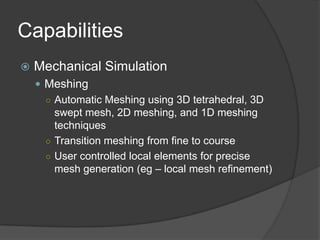
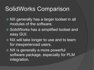
UGS NX by SiemensJoseph CosentinoBen KowalewskiPeter Vandermeer
AgendaIntroductionUsers of NX“Life” DemoExamples of CapabilitiesComparisonQuestions
IntroductionNX is developed by Siemens PLM SoftwareSynchronous Technology (introduced in NX 6)Capabilities:Mechanical Design/SimulationElectromechanical Systems Design/SimulationEngineering Process Management (Teamcenter)Industrial Design & StylingPackage DesignTooling and Fixture DesignInspection Programming
Users of NXMechanical and Manufacturing IndustriesGM, Nissan, Moog, GE, Pratt & WhitneySoftware was used in 90% of the vehicles on display at the North American International Auto Show
“Life” DemoPerformed by Joe CosentinoStress Analysis of C-clamp
Comparison .15 Mesh Von MisesUGS NX SolutionSolidWorks Solution
Comparison .1 Mesh Von MisesSolidWorks SolutionUGS NX Solution
CapabilitiesMechanical DesignModeling ToolsFeature based parametric design, with product features such as holes, bosses, cutouts, and fillets.Design intent captured up front to allow for intuitive future changesOther explicit techniques include curve and spline definition, sweeps, revolves, Boolean operations, and precise surface modeling through curves and points.
CapabilitiesMechanical DesignDraftingAutomatic and associative view projections and scalingEasy to create standard and custom section viewsAssembly drawing view applications, such as non-sectioned component display in section views.Easy to dimension, apply GD&T callouts, edit text manually, apply notes, drawing templates, utility symbols, parts lists and tables, and more.Easy to use intuitive interface.
CapabilitiesMechanical Design: Other TopicsAssembly DesignHuman ModelingProduct ValidationRouted Systems DesignSheet Metal DesignUser-Defined Features
CapabilitiesMechanical SimulationMeshingAutomatic Meshing using 3D tetrahedral, 3D swept mesh, 2D meshing, and 1D meshing techniquesTransition meshing from fine to courseUser controlled local elements for precise mesh generation (eg – local mesh refinement)
CapabilitiesMechanical SimulationLoads and Boundary ConditionsLoad definition on associated geometry (eg – a mesh point, face, edge, or curve)Constraints defined on associated geometrySupport for surface to surface contactsLoads include: Forces, temperatures, face and edge pressures, acceleration, heat sources, face and edge fluxes, convection and radiationTime varying loading
CapabilitiesMechanical SimulationSolver EnvironmentsNastran – structural, thermalAbaqus – structural, thermalAnsys – structural, thermalNX Thermal / Advanced ThermalNX Flow – fluid flow and coupled thermal/flowNX Advanced Flow
CapabilitiesMachiningProgram Computer Automated Manufacturing Tools to Machine Your ProductDrilling, Multi-Axis Milling, Turning, Wire EDM machining, Machining Simulation (Including collision detection between the part, tools, and fixturing)
SolidWorks ComparisonNX generally has a larger toolset in all modules of the software.SolidWorks has a simplified toolset and easy GUI.NX will take longer to use and to learn for inexperienced users.NX is generally a more powerful software package, especially for PLM integration.
Interface Demo
Questions??

UGS NX

  • 1.
    UGS NX bySiemensJoseph CosentinoBen KowalewskiPeter Vandermeer
  • 2.
    AgendaIntroductionUsers of NX“Life”DemoExamples of CapabilitiesComparisonQuestions
  • 3.
    IntroductionNX is developedby Siemens PLM SoftwareSynchronous Technology (introduced in NX 6)Capabilities:Mechanical Design/SimulationElectromechanical Systems Design/SimulationEngineering Process Management (Teamcenter)Industrial Design & StylingPackage DesignTooling and Fixture DesignInspection Programming
  • 4.
    Users of NXMechanicaland Manufacturing IndustriesGM, Nissan, Moog, GE, Pratt & WhitneySoftware was used in 90% of the vehicles on display at the North American International Auto Show
  • 5.
    “Life” DemoPerformed byJoe CosentinoStress Analysis of C-clamp
  • 6.
    Comparison .15 MeshVon MisesUGS NX SolutionSolidWorks Solution
  • 7.
    Comparison .1 MeshVon MisesSolidWorks SolutionUGS NX Solution
  • 8.
    CapabilitiesMechanical DesignModeling ToolsFeaturebased parametric design, with product features such as holes, bosses, cutouts, and fillets.Design intent captured up front to allow for intuitive future changesOther explicit techniques include curve and spline definition, sweeps, revolves, Boolean operations, and precise surface modeling through curves and points.
  • 9.
    CapabilitiesMechanical DesignDraftingAutomatic andassociative view projections and scalingEasy to create standard and custom section viewsAssembly drawing view applications, such as non-sectioned component display in section views.Easy to dimension, apply GD&T callouts, edit text manually, apply notes, drawing templates, utility symbols, parts lists and tables, and more.Easy to use intuitive interface.
  • 10.
    CapabilitiesMechanical Design: OtherTopicsAssembly DesignHuman ModelingProduct ValidationRouted Systems DesignSheet Metal DesignUser-Defined Features
  • 11.
    CapabilitiesMechanical SimulationMeshingAutomatic Meshingusing 3D tetrahedral, 3D swept mesh, 2D meshing, and 1D meshing techniquesTransition meshing from fine to courseUser controlled local elements for precise mesh generation (eg – local mesh refinement)
  • 12.
    CapabilitiesMechanical SimulationLoads andBoundary ConditionsLoad definition on associated geometry (eg – a mesh point, face, edge, or curve)Constraints defined on associated geometrySupport for surface to surface contactsLoads include: Forces, temperatures, face and edge pressures, acceleration, heat sources, face and edge fluxes, convection and radiationTime varying loading
  • 13.
    CapabilitiesMechanical SimulationSolver EnvironmentsNastran– structural, thermalAbaqus – structural, thermalAnsys – structural, thermalNX Thermal / Advanced ThermalNX Flow – fluid flow and coupled thermal/flowNX Advanced Flow
  • 14.
    CapabilitiesMachiningProgram Computer AutomatedManufacturing Tools to Machine Your ProductDrilling, Multi-Axis Milling, Turning, Wire EDM machining, Machining Simulation (Including collision detection between the part, tools, and fixturing)
  • 15.
    SolidWorks ComparisonNX generallyhas a larger toolset in all modules of the software.SolidWorks has a simplified toolset and easy GUI.NX will take longer to use and to learn for inexperienced users.NX is generally a more powerful software package, especially for PLM integration.
  • 16.
  • 17.