Downloaded 169 times

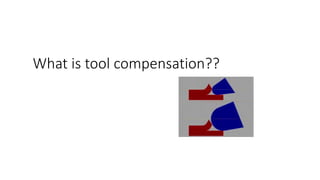
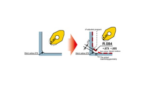
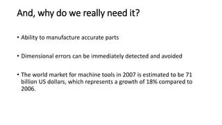

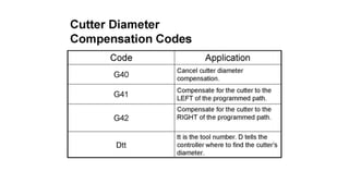
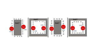
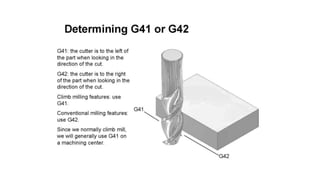
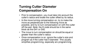
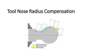
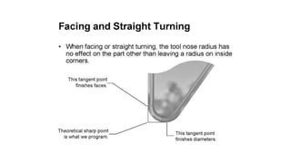
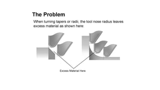
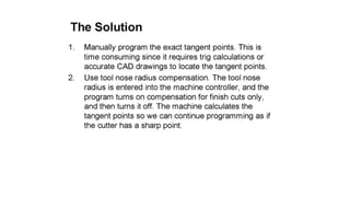
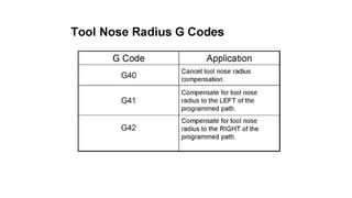
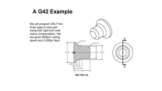
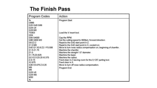
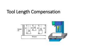
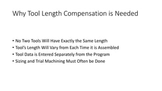
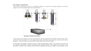
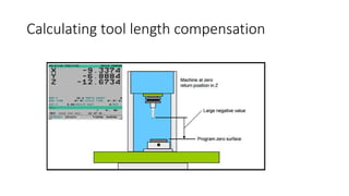


The document discusses tool compensation in machining, emphasizing its importance for manufacturing accurate parts and reducing dimensional errors. It covers various types of tool compensation, such as cutter radius, tool nose radius, and tool length compensation, while detailing the process of calculating tool length compensation using G codes. Additionally, it introduces touch-trigger probes (TTPs) in CNC turning for on-machine measurement and automatic tool compensation, highlighting their operational principles and factors affecting their performance.