This document provides an overview of CATIA V5 software for industrial training purposes. It covers the following key points in 3 sentences:
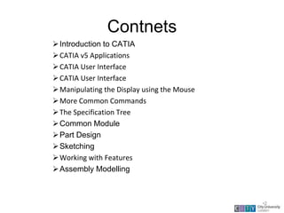
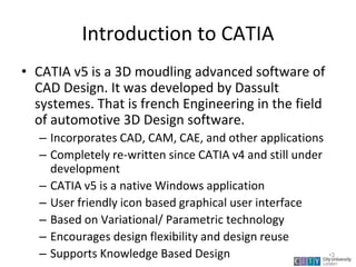
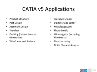
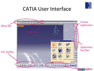
CATIA V5 is a 3D modeling software used for mechanical design that incorporates CAD, CAM, and CAE applications. The document outlines the CATIA user interface and common commands, and provides examples of how to use the sketching, part design, and assembly modeling modules to create 3D models from 2D profiles and assemble multiple parts. It summarizes the capabilities of these modules and how they can be used to efficiently create and modify complex 3D models.


![Inventor notes[1]](https://cdn.slidesharecdn.com/ss_thumbnails/inventornotes1-160125233002-thumbnail.jpg?width=640&height=640&fit=bounds)