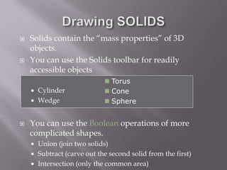
The document provides an overview of AutoCAD and its features for 2D and 3D computer-aided design. It discusses commands for drawing basic 2D shapes like lines and rectangles. It also covers more advanced topics such as object snaps, zooming and panning, editing objects, user coordinate systems, and drawing 3D solids and applying hatch patterns. A variety of tools and techniques are presented for working efficiently in AutoCAD.


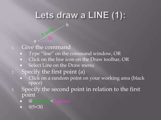


![ The PLINE command creates a chain line with
multiple vertexes and straight or circular
segments between the vertexes
Draw a closed shape with the pline command:
Then type PEDIT (polyline edit) on the
command line and see what you can do with
it:
Enter an option [Close/Join/Width/Edit
vertex/Fit/Spline/Decurve/Ltype gen/Undo]:
Try Width and Spline](https://image.slidesharecdn.com/shubhamppton-230112144309-f9c4c398/85/autocad-ppt-16-320.jpg)


![solidworks1-171128203129[1].pptx](https://cdn.slidesharecdn.com/ss_thumbnails/solidworks1-1711282031291-231012152836-e87ded6f-thumbnail.jpg?width=640&height=640&fit=bounds)


