Download to read offline
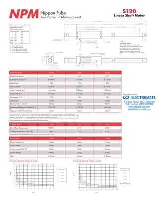
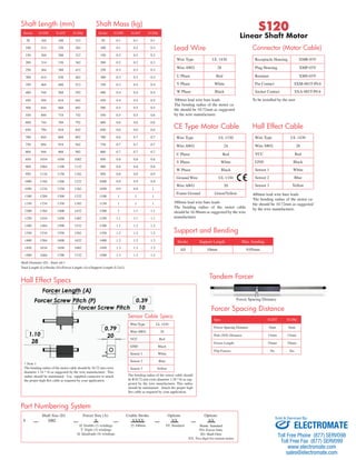

This document provides specifications for Nippon Pulse linear shaft motors, including the S120D, S120T, and S120Q models. It lists technical details such as continuous and peak forces, resistance, inductance, and more. Dimensions for the forcer length, width, and screw pitch are provided for each motor model. Force versus duty curves are displayed for the S120D and S120Q.


