Download to read offline

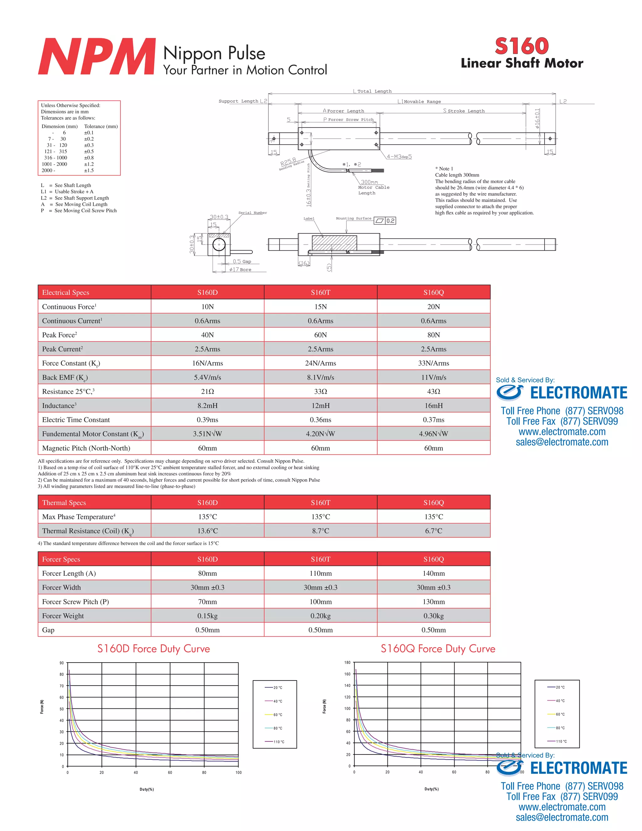
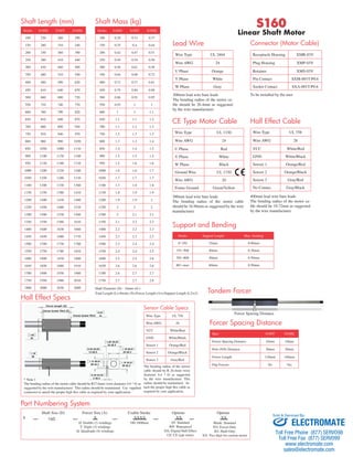

This document provides specifications for the Nippon Pulse S160 series linear shaft motors, including dimensions, electrical specifications, force and thermal characteristics, and part numbering information. The linear motors come in three models (S160D, S160T, S160Q) with different continuous forces, stroke lengths up to 1800mm, and customizable configurations. Technical details are given for the motor, sensor and hall effect cabling.


