Download to read offline
![ISDBCR-ESD/ISPDBCR-ESD A1
High precision
specification
ESD
Single-axis robot for cleanroom/Electrostatic discharge specification
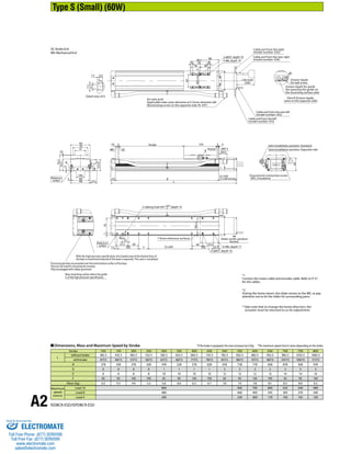
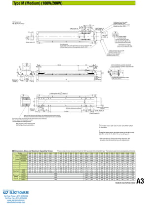
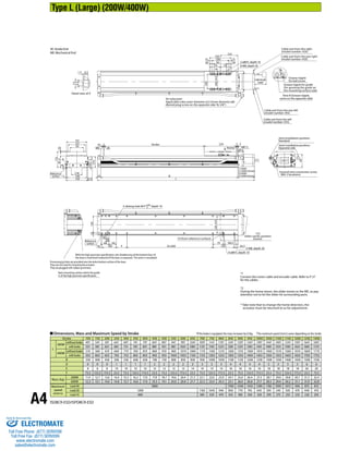
Type S (W: 90 mm)/Type M (W: 120 mm)/Type L (W:150 mm)
Single-axis robot for cleanroom/Electrostatic discharge specification
Type S (W: 90 mm)/Type M (W: 120 mm)/Type L (W:150 mm)
Series Type Encoder type Motor type Lead Stroke Applicable controller Cable length Options
N : None
S : 3m
M : 5m
X: Specified length
*1.0G=9800mm/sec2
ISDBCR-ESD
ISPDBCR-ESD
Model
Specification
Items
ISDBCR: Standard
specification
ISPDBCR: High precision
specification
S: Small
M: Medium
L: Large
* Refer to P. 10 for the details of items comprising the model number.
Model Number/Specification
100: 100mm
1300: 1300mm
(in 50mm increments)
A: Absolute
specification
I: Incremental
specification
60: 60W
100: 100W
200: 200W
400: 400W
10 : 10mm
8 : 8mm
5 : 5mm
4 : 4mm
40 : 40mm
30 : 30mm
20 : 20mm
16 : 16mm
T1: XSEL-J/K
T2: SCON
SSEL
XSEL-P/Q
Refer to the
options table
below.
* In the above model numbers, indicates the encoder type, indicates the stroke, indicates the applicable controller, indicates the cable length, and indicates the option(s).
Option Common Specifications
Applicable
Controller
Maximum number
of controlled axes
Connectable
encoder type
Operating
method
Power-supply
voltage
Reference
page
X-SEL-P/Q 6 axes
Absolute/
incremental
Program
Single/three-phase
200 VAC ➔P56
X-SEL-J/K 4 axes Single-phase
100/200 VAC
➔P56
SSEL 2 axes ➔P56
SCON 1 axis Positioner pulse
train control
Sincle-phase 200 VAC
for 400W motor spec ➔P56
Positioning repeatability (Note 2) ±0.01mm [±0.005mm]
Drive method (Note 3)
S type: Ball screw ø12mm, rolled C10 [equivalent to rolled C5]
M type: Ball screw ø16mm, rolled C10 [equivalent to rolled C5]
L type: Ball screw ø20mm, rolled C10 [equivalent to rolled C5]
Lost Motion (Note 4) 0.05mm [0.02mm] max.
Dynamic allowable load moment
(Note 5)
S type: Ma: 28.4N•m Mb: 40.2N•m Mc: 65.7N•m
M type: Ma: 69.6N•m Mb: 99.0N•m Mc: 161.7N•m
L type: Ma: 104.9N•m Mb: 149.9N•m Mc: 248.9N•m
Overhang load length
S type: Ma direction: 450mm max. Mb, Mc directions: 450mm max.
M type: Ma direction: 600mm max. Mb, Mc directions: 600mm max.
L type: Ma direction: 750mm max. Mb, Mc directions: 750mm max.
Dynamic straightness (Note 6) 0.02mm/m max.
Base Material: Aluminum, with white alumite treatment
Applicable controller T1: XSEL-J/K T2: XSEL-P/Q, SSEL, SCON
Cable length (Note 7) N: None, S: 3m, M: 5m, X: Specified length
Grease Low dust-raising grease (for ball screw and guide)
Cleanliness degree Class 10 (0.1μm per 1cf)
Suction tube joint Quick connect joint, applicable tube outer diameter ø12mm
Model number Encoder
type
Motor
output
(W)
Lead
(mm)
Stroke in
50mm
increments
(mm)
Speed
(mm/s)
Acceleration (Note 1) Payload (Note 1)
Rated
thrust
(N)
Suction
flow rate
(N /min)
Horizontal (G) Vertical (G) Horizontal (Kg) Vertical (Kg)*
Rated Maximum Rated Maximum Rated
acceleration
Maximum
acceleration
Rated
acceleration
Maximum
acceleration
ISDBCR[ISPDBCR]-S- ① -60-16- ② - ③ - ④ -ESD- ⑤
Absolute
Incremental 60
16
100~800
1~960 0.4 1 0.4 0.8 13 4.5 3 2 53.1 60
ISDBCR[ISPDBCR]-S- ① -60-8- ② - ③ - ④ -ESD- ⑤ 8 1~480 0.4 0.7 0.4 0.6 27 12 6 5 106.1 30
ISDBCR[ISPDBCR]-S- ① -60-4- ② - ③ - ④ -ESD- ⑤ 4 1~240 0.2 0.5 0.2 0.4 55 30 14 12 212.3 15
ISDBCR[ISPDBCR]-M- ① -100-30- ② - ③ - ④ -ESD- ⑤
Absolute
Incremental 100
30
100~1100
1~1800 0.4 1 0.4 1 15 4 2 1.2 56.6 180
ISDBCR[ISPDBCR]-M- ① -100-20- ② - ③ - ④ -ESD- ⑤ 20 1~1200 0.4 1 0.4 1 23 8 4 2.5 84.9 120
ISDBCR[ISPDBCR]-M- ① -100-10- ② - ③ - ④ -ESD- ⑤ 10 1~600 0.4 0.7 0.4 0.6 45 20 10 7 169.8 50
ISDBCR[ISPDBCR]-M- ① -100-5- ② - ③ - ④ -ESD- ⑤ 5 1~300 0.2 0.5 0.2 0.4 85 45 20 15 339.7 20
ISDBCR[ISPDBCR]-M- ① -200-30- ② - ③ - ④ -ESD- ⑤
Absolute
Incremental 200
30
100~1100
1~1800 0.4 1 0.4 1 30 12 6 3 113.9 180
ISDBCR[ISPDBCR]-M- ① -200-20- ② - ③ - ④ -ESD- ⑤ 20 1~1200 0.4 1 0.4 1 45 16 10 5 170.9 120
ISDBCR[ISPDBCR]-M- ① -200-10- ② - ③ - ④ -ESD- ⑤ 10 1~600 0.4 0.7 0.4 0.6 90 40 20 15 341.8 50
ISDBCR[ISPDBCR]-M- ① -200-5- ② - ③ - ④ -ESD- ⑤ 5 1~300 0.2 0.5 0.2 0.4 110 80 40 30 683.6 20
ISDBCR[ISPDBCR]-L- ① -200-40- ② - ③ - ④ -ESD- ⑤
Absolute
Incremental 200
40
100~1300
1~1800 0.4 1 0.4 1 15 7 2.5 2 85.5 180
ISDBCR[ISPDBCR]-L- ① -200-20- ② - ③ - ④ -ESD- ⑤ 20 1~1200 0.4 1 0.4 1 45 15 9 5 170.9 120
ISDBCR[ISPDBCR]-L- ① -200-10- ② - ③ - ④ -ESD- ⑤ 10 1~600 0.4 0.7 0.4 0.6 90 40 20 14 341.8 50
ISDBCR[ISPDBCR]-L- ① -400-40- ② - ③ - ④ -ESD- ⑤
Absolute
Incremental 400
40
100~1300
1~1800 0.4 1 0.4 1 40 17 8 5 169.6 180
ISDBCR[ISPDBCR]-L- ① -400-20- ② - ③ - ④ -ESD- ⑤ 20 1~1200 0.4 1 0.4 1 90 30 20 10 339.1 120
ISDBCR[ISPDBCR]-L- ① -400-10- ② - ③ - ④ -ESD- ⑤ 10 1~600 0.4 0.7 0.4 0.6 120 60 40 30 678.3 50
Applicable Controller Specifications
(Note 1) Refer to P. 9 for the relationship of acceleration and payload.
(Notes 2, 3, 4) The values in [ ] apply to the ISPDBCR series. Other
specification values apply commonly to the ISDBCR and ISPDBCR.
(Note 5) When the traveling life is 10,000km.
(Note 6) The value of dynamic straightness is when the high straightness,
precision specification (option) is specified.
(Note 7) The maximum cable length is 30m. Specify a desired length in
meters.
(Example. X08 = 8m)
Name Model
number
Reference
page Name Model
number
Reference
page
Cable exit from the left A1S ➔P11 Home limit switch L ➔P11
Cable exit from the rear left A1E ➔P11 Home limit switch on the opposite side LL ➔P11
Cable exit from the right A3S ➔P11 Master axis specification LM ➔P12
Cable exit from the rear right A3E ➔P11 Master axis specification (sensor on the opposite side) LLM ➔P12
AQ seal (standard feature) AQ ➔P11 Non-motor side specification NM ➔P12
Brake B ➔P11 Guide with ball retention mechanism RT ➔P12
Creep sensor C ➔P11 Slave axis specification S ➔P12
Creep sensor on the opposite side CL ➔P11 High straightness, precision specification ST ➔P13
Suction tube joint on the opposite side VR ➔P12
Sold & Serviced By:
ELECTROMATE
Toll Free Phone (877) SERVO98
Toll Free Fax (877) SERV099
www.electromate.com
sales@electromate.com](https://image.slidesharecdn.com/iaiisdbcrispdbcresdspecsheet-141008213500-conversion-gate01/85/Iai-isdbcr-ispdbcr_esd_specsheet-1-320.jpg)

This document provides specifications for the ISDBCR-ESD/ISPDBCR-ESD A1 single-axis robot for cleanrooms. It includes details on model types and numbers, dimensions, speeds, payloads, accuracies, and other technical specifications. Precision and standard models are available in small, medium, and large sizes with various motor outputs, strokes, speeds, and payload capabilities. Options include different cable exits, brakes, sensors, controllers, and other accessories. Precise positioning repeatability, straightness, and load specifications are provided.


