Download to read offline
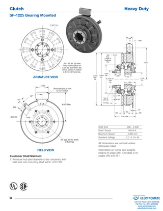
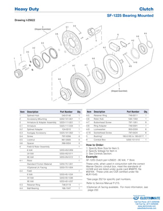

This document provides specifications for the Clutch Heavy Duty SF-1225 Bearing Mounted clutch. It lists dimensions, torque and speed ratings, voltage options, and part numbers for the components. The clutch has a shaft size range of 0.500-2.500 inches, a static torque of 465 lb-ft, and can operate at up to 2,200 rpm. It includes an exploded diagram labeling the individual parts.


![5G Explained! A High Level Overview [Introduction]](https://cdn.slidesharecdn.com/ss_thumbnails/5gexplainedahighleveloverview-260119165306-cc137a3e-thumbnail.jpg?width=640&height=640&fit=bounds)


