Download to read offline
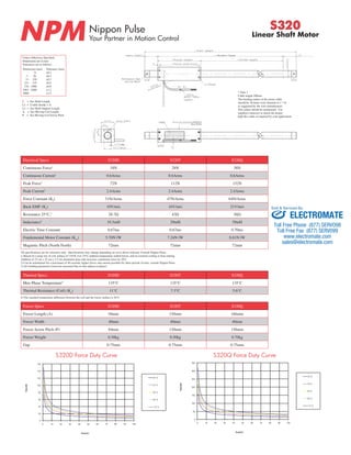
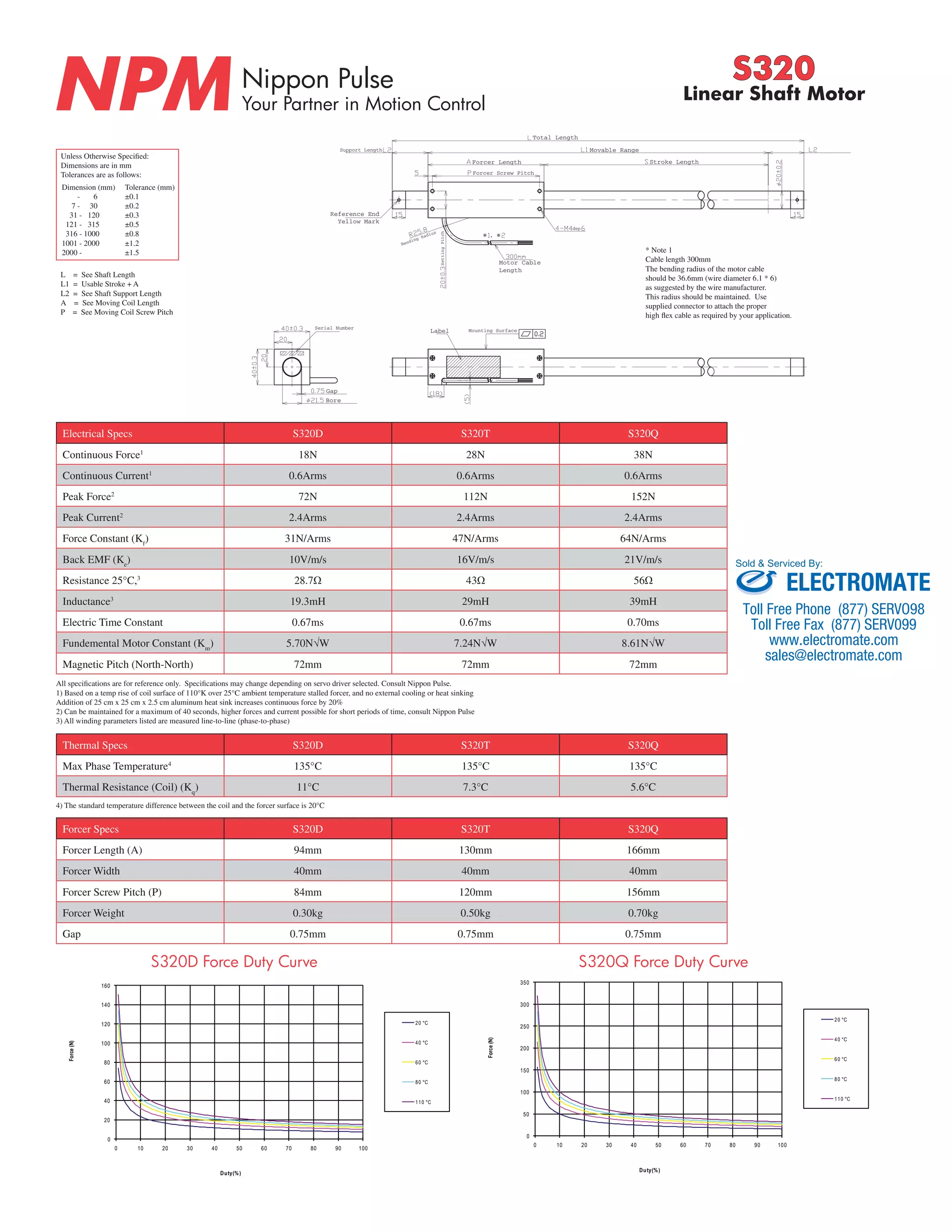
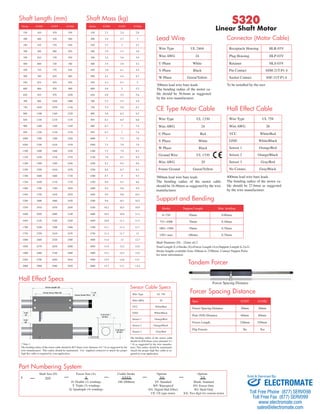

This document provides specifications for the Nippon Pulse S320 linear shaft motor in 3 variants: S320D, S320T, and S320Q. It lists electrical specifications including continuous and peak forces, currents, resistance, inductance and more. It also provides physical dimensions for the motor like usable stroke length, forcer length and weight, screw pitch, and force-duty curves. Tolerances for dimensions are included.


