Download to read offline
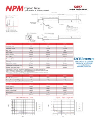

This document provides specifications for Nippon Pulse linear shaft motors models S427D, S427T, and S427Q. It lists electrical specifications including continuous and peak force and current, force and back EMF constants, resistance, inductance and more. It also provides dimensions, weights, temperature ratings and force-duty curves for the different models. Additional information is given on shaft lengths, strokes, cable specifications and part numbering.


![5G Explained! A High Level Overview [Introduction]](https://cdn.slidesharecdn.com/ss_thumbnails/5gexplainedahighleveloverview-260119165306-cc137a3e-thumbnail.jpg?width=640&height=640&fit=bounds)


