Download to read offline
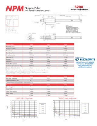

The document provides specifications for the Nippon Pulse S200 series of linear shaft motors, including the S200D, S200T, and S200Q models. It lists electrical specifications, force and current ratings, dimensions, weights, tolerances, and other technical details. Installation and wiring instructions are also provided.


![5G Explained! A High Level Overview [Introduction]](https://cdn.slidesharecdn.com/ss_thumbnails/5gexplainedahighleveloverview-260119165306-cc137a3e-thumbnail.jpg?width=640&height=640&fit=bounds)


