Download to read offline
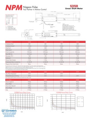

This document provides specifications for Nippon Pulse's S250 series of linear shaft motors, including dimensions, electrical characteristics, force capabilities, and thermal properties for the S250D, S250T, S250Q, and S250X models. Stroke lengths are available from 100 to 2000mm. The document also includes diagrams of motor components, wiring diagrams, and part numbering conventions.


![5G Explained! A High Level Overview [Introduction]](https://cdn.slidesharecdn.com/ss_thumbnails/5gexplainedahighleveloverview-260119165306-cc137a3e-thumbnail.jpg?width=640&height=640&fit=bounds)


