Download to read offline
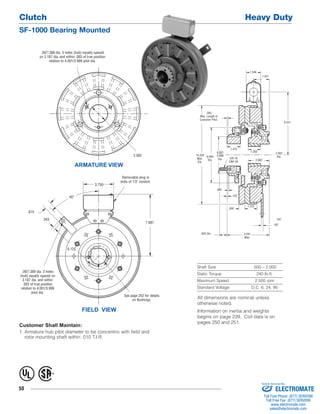
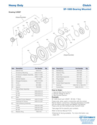

This document provides specifications for the Warner Electric SF-1000 Bearing Mounted Heavy Duty Clutch. The clutch has a shaft size range of 0.5-2 inches, a static torque of 240 lb-ft, and can operate at speeds up to 2,500 rpm. It uses DC voltages of 6, 24, or 90. Dimensions and part numbers are provided for the various components. Maintenance requirements and ordering information are also listed.


